
K-WANG


Kollmorgen SERVOSTAR 600 (S600) series digital servo drive
Kollmorgen SERVOSTAR 600 (S600) series digital servo drive
Product Overview and Model Code
Product Core Positioning
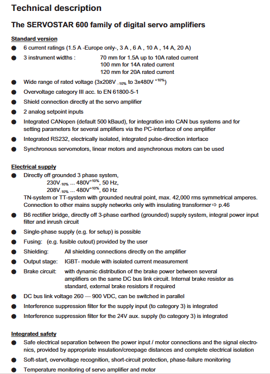
The S600 series is a digital servo drive launched by Kollmorgen for medium to high power and high-precision motion control scenarios. The hardware version has been iterated to 05.40 and supports multiple types of feedback devices and bus expansion. It can also be equipped with an optional AS restart lock safety function, and is compatible with synchronous servo motors, linear motors, and asynchronous motors. It can expand I/O and communication capabilities through expansion cards. Its core advantages lie in medium to high power coverage, high control accuracy, and flexible expansion. It is widely used in automation production lines, multi axis collaborative equipment, precision machine tools, and other scenarios.
Model coding rules
The model consists of "series+current level+voltage type+function options+expansion card", and the core coding dimensions and example analysis are as follows:
Explanation of the meaning of the coding section and key codes
Series Identification Core Product Series S601 (1.5ARMS), S603 (3ARMS), S610 (10ARMS), S620 (20ARMS)
Current level Continuous current specifications 01 (1.5ARMS), 03 (3ARMS), 10 (10ARMS), 20 (20ARMS)
Voltage type power supply input type 0 (3 × 208-480VAC)
Function Options Core Function Configuration - NA (No Extension), - AS (Restart Lock Function)
Expansion card optional expansion modules OPT-EI (I/O-14/08), OPT-PB (PROFIBUS), OPT-EC (EtherCAT)
Core Technical Parameters
Power Supply and Current Parameters
Model Supply Voltage Continuous Current (ARMS) Peak Current (ARMS) Maximum DC Bus Voltage (VDC) Heat Loss (W)
S601 3×208-480VAC 1.5 3 675 15
S603 3×208-480VAC 3 6 675 30
S606 3×208-480VAC 6 12 675 60
S610 3×208-480VAC 10 20 675 90
S614 3×208-480VAC 14 28 675 120
S620 3×208-480VAC 20 40(2s) 675 150
Control Performance and Safety Parameters
Dynamic performance: Switching frequency of 8kHz (optional 16kHz below 400V), current loop bandwidth>1.2kHz, speed loop update cycle of 65 μ s/250 μ s, position loop update cycle of 250 μ s
Feedback resolution: Sin Cos encoder supports 1Vpp signal, EnDat2.1/HIPERFACE supports high-resolution absolute feedback
Security function: - AS restart lock function complies with EN954-1, supports security category 1/3, response time ≤ 1ms
Braking circuit: Built in braking resistor (66 Ω for 601/603, 33 Ω for 606-620), supports external braking resistor expansion, braking threshold 400-870VDC
Installation and wiring specifications
Installation Requirements
Installation method: Vertically installed on a conductive grounding surface, the control cabinet requires forced ventilation
Cooling gap: top/bottom ≥ 45mm, side ≥ 70mm, high-power models (S614/S620) require the installation of a fan
Mechanical dimensions: Width 70-120mm (70mm for 1.5-10ARMS, 100mm for 14ARMS, 120mm for 20ARMS), height 275mm, depth 265mm, weight 4-7.5kg
Environmental restrictions: Working temperature 0-45 ℃ (with a capacity reduction of 2.5%/℃ for 45-55 ℃), humidity 10-85% (without condensation), altitude<1000m (with a capacity reduction of 1.5%/100m for 1000-2500m)
Core interface wiring
The manual provides detailed wiring definitions for 15 core interfaces, with the following key points:
Power wiring: X0A/X0B interface connected to 3-phase main power supply, L1/L2/L3 phase connected, PE grounding in accordance with IEC 60364 specification
DC bus wiring: The X7 interface supports parallel connection of multiple drivers (total current ≤ 40A), requiring the use of 2.5mm ² shielded cables with a length ≤ 200mm
Motor wiring: X9 interface connects U/V/W three-phase, brake signal BRAKE+/BRAKE - supports 24VDC/2A brake control, motor cable>25m requires motor choke coil 3YL
Feedback wiring: X1 supports Sin Cos/BiSS/EnDet, X2 supports Resolvers, X5 supports SSI/incremental encoders, feedback cables require twisted pair shielding
-AS functional wiring: The X10 interface is connected to a 24V control signal and must be wired according to EN954-1 specifications to ensure activation after mechanical load locking
Parameter Configuration and Control Mode
Basic Configuration
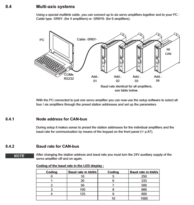
Station address and baud rate: Set through the front panel buttons, CANopen defaults to a baud rate of 500kBaud and supports 10-1000kBaud adjustable
-AS configuration: An external safety relay (compliant with EN954-1) is required, and wiring should be kept away from power cables. Before activation, ensure that the motor is stopped (speed ≤ 5rpm)
Braking threshold: Set through DRIVE. EXE software, default 400VDC (230VAC model), 720VDC (400VAC model), 840VDC (480VAC model)
Core parameter configuration
Parameter Category Key Parameter Function Description Value Range
Current loop Kp proportional gain 0.1-100 V/A
Speed loop Kp Speed loop proportional gain 0.1-100 ARMS/rad/s
Speed loop Ki Speed loop Integral gain 0-1000 Hz
Position loop Kpp Position loop proportional gain 0.1-100 Hz
Electronic Gear GearIn/GearOut Electronic Gear Ratio 1-65535
Current limit I RMS/I Peak Continuous/Peak current limit 0-100% rated value
Feedback configuration FBTYPE feedback type selection 0 (Resolver), 20 (BiSS), etc
Control mode configuration
Torque mode: Supports ± 10V analog commands, with a resolution of 14 bits, suitable for torque closed-loop control scenarios
Speed mode: Supports analog commands, pulse commands, or bus commands, with a stable speed accuracy of ± 0.1% and a maximum speed of 6000rpm
Position mode: Supports step direction (1.5MHz), electronic gear, multi axis master-slave cooperation, and position error window can be set
Electronic gear: supports external encoder as the main shaft, follows proportionally from the shaft, with a gear ratio accuracy of 1/65535
Troubleshooting and Maintenance
Core fault codes and troubleshooting
Fault codes, fault types, common causes, troubleshooting methods
F01 heat sink overheating environment temperature is too high, and the heat dissipation gap is insufficient. Clean the heat dissipation channel, reduce the load, and check the fan
F02 bus overvoltage brake resistor failure, rapid deceleration check brake resistor wiring, extend deceleration time, install external brake resistor
F04 feedback fault feedback cable breakage, wiring error check feedback wiring, measure feedback power supply, replace cable
F06 motor overheating, motor overload, thermal sensor failure to reduce load, check motor thermal sensor wiring, measure winding temperature
F27-AS function failure - AS enables effective adjustment of control logic simultaneously with ENABLE to ensure that the motor has stopped before AS activation
Key points of daily maintenance
Regular inspection: cleaning of heat dissipation channels, fastening of wiring terminals, integrity of feedback cable shielding, recommended every 6 months
Capacitor reformation: When stored for more than 1 year without use, 230VAC single-phase electricity needs to be added for 30 minutes to activate the capacitor
Parameter backup: Backup parameters (. cfg files) through DRIVE. EXE software to avoid configuration loss due to misoperation
Expansion card maintenance: When inserting or removing expansion cards, power must be turned off. During installation, ensure that the guide rail is inserted into place and the screws are tightened
Expansion Cards and Accessories
Core Expansion Card
Expansion card type, model, core function, interface type
I/O Expansion OPT-EI 14 channel digital input, 8 channel digital output MiniCombicon
PROFIBUS OPT-PB supports PROFIBUS DP protocol SubD 9-pin
EtherCAT OPT-EC supports EtherCAT bus and RJ45 ring network topology
SynqNet OPT-SN supports SynqNet network and multi axis synchronous RJ45
Dual CAN OPT-2CAN separates RS232 and CAN interfaces, supports bus terminal SubD 9-pin x 3
DeviceNet OPT-DN supports the DeviceNet protocol and has adjustable node addresses for MiniCombicon
Special Accessories
Braking resistor: Supports 200-1500W external braking resistor, recommended resistance value of 33 Ω (universal across the entire series)
Cable: Dedicated motor/feedback cable, supports single cable connection, protection level IP67
Connector: X0/X7/X9 dedicated connector, suitable for current carrying requirements of different voltage levels
Software tool: DRIVE. EXE (Windows compatible), supports parameter configuration, oscilloscope monitoring, and fault diagnosis
- YOKOGAWA
- Reliance
- ADVANCED
- SEW
- ProSoft
- WATLOW
- Kongsberg
- FANUC
- VSD
- DCS
- PLC
- man-machine
- Covid-19
- Energy and Gender
- Energy Access
- Renewable Integration
- Energy Subsidies
- Energy and Water
- Net zero emission
- Energy Security
- Critical Minerals
- A-B
- petroleum
- Mine scale
- Sewage treatment
- cement
- architecture
- Industrial information
- New energy
- Automobile market
- electricity
- Construction site
- HIMA
- ABB
- Rockwell
- Schneider Modicon
- Siemens
- xYCOM
- Yaskawa
- Woodward
- BOSCH Rexroth
- MOOG
- General Electric
- American NI
- Rolls-Royce
- CTI
- Honeywell
- EMERSON
- MAN
- GE
- TRICONEX
- Control Wave
- ALSTOM
- AMAT
- STUDER
- KONGSBERG
- MOTOROLA
- DANAHER MOTION
- Bentley
- Galil
- EATON
- MOLEX
- Triconex
- DEIF
- B&W
- ZYGO
- Aerotech
- DANFOSS
- KOLLMORGEN
- Beijer
- Endress+Hauser
- schneider
- Foxboro
- KB
- REXROTH
- YAMAHA
- Johnson
- Westinghouse
- WAGO
- TOSHIBA
- TEKTRONIX
- BENDER
- BMCM
- SMC
- HITACHI
- HIRSCHMANN
- XP POWER
- Baldor
- Meggitt
- SHINKAWA
- Other Brands
- UniOP
- KUKA
- IBA
- Beckhoff
- ADLINK
-
ADLINK HPCI-14S12U - Industrial Control Backplane 12PCI Backplane PCI-14S Passive Backplane
-
ADLINK PCIe-GIE74C - image acquisition card 4-CH GigE Vision PoE+ Frame Grabber
-
ADLINK PCI-8164 - control card 4-Axis Advanced Motion Controller Board
-
ADLINK PCIe-U304 - 4 Port USB3 PCIe Frame Grabbers USB Screw Hole Card
-
ADLINK PCI-9112 - Multi-Function Data Acquisition Card DAQ Card
-
ADLINK PCI-7432 - 51-12013-0A50 4-CH Isolated Numérique I/O PCI Cartes Digital I/O Card
-
ADLINK PCA-6106P3-0C1 REV.C1 - backplane 6-Slot Passive Backplane Board
-
ADLINK PCI-7224 - 24-CH Opto-Isolated Digital I/O PCI Board
-
ADLINK CPCI-7433R(G) - Digital Input Board Rear I/O CompactPCI Card
-
ADLINK EBP-13E4 - 51-46703-0A30 Industrial PC Backplane Passive Backplane
-
ADLINK PCIE-HDV62 - Image acquisition card High Definition Video Frame Grabber
-
ADLINK EBP-13E4 - 51-46703-0A30 Industrial Backplane Board Passive Backplane
-
ADLINK 90111-B1 / CPCI-6770 - PCB CPU MODULE CompactPCI Single Board Computer
-
ADLINK PCI-7248 - DATA ACQUISITION PCI CARD 48-CH Parallel Digital I/O Board
-
ADLINK PCI-7230 - 51-12003-0a50 board PCI7230 32-CH Isolated Digital I/O Card
-
ADLINK PCI2A000CB - 51-20000-0B30 Multi-Function DAQ Card Baseboard
-
ADLINK PCI-8134-005 - 4-Axis Motion Controller Card
-
ADLINK PCI-7224 - 24-CH Opto-Isolated Digital I/O PCI Card
-
ADLINK PCI-7434 - 64-CH Isolated Digital Output Card
-
ADLINK PCI-8132 - motion control card 2-Axis Servo & Stepper Controller
-
ADLINK PCI-8134 - Motion Controller PCI Card 4-Axis Controller Board
-
ADLINK PCI-8164 - Motion Control Card 51-12406-0A40 4-Axis Controller
-
ADLINK 51-12001-0C20 - Circuit Board Data Acquisition Interface Module Hardware
-
ADLINK NuPR0-840 - industrial control motherboard Full-Size PICMG CPU Board
-
ADLINK PCI-7444 - 51-12023-0A10 card 128-CH Isolated Digital Output Board
-
ADLINK PCI-1612B - data acquisition card 4-Port RS-232/422/485 Serial Communication Card
-
ADLINK PCI-6208V 009 - 8/16-CH 16-Bit Analog Output Cards PCB-I-E-482=6BX3
-
ADLINK NUPRO-935A/LV - industrial control motherboard Full-Size PICMG SBC Board
-
ADLINK PCI-9114DG - Multi-Function DAQ Card Data Acquisition PCI Card
-
ADLINK ACL-7130 - Data acquisition card Isolated Digital I/O Board
-
ADLINK ABX-6300D-4E1-BP - board ABX6300D4E1BP Video Interface Expansion Card
-
ADLINK CPCI-6940 - CPCI-6940/D1539/M16-0(EA)-000E 6U CompactPCI Processor Board
-
ADLINK NuPRO-760 - industrial control motherboard Half-Size PICMG SBC CPU Board
-
ADLINK IMB-M42H (G)-0020 - industrial control motherboard LGA1155 Micro-ATX Mainboard
-
ADLINK RTV-24 / PCI-MP4S - 51-12519-1C30 4-Channel Real Time Video Capture Board
-
ADLINK PCI-8134 - 4-Axis Servo & Stepper Motion Controller Card
-
ADLINK MXC-6101D - V.PC000.002.ST.00 Box PC Configurable Embedded Computer
-
ADLINK PCI-8134A - 51-12421-0A10 Motion Control Card 4-Axis Controller Card
-
ADLINK DIN-100S / DIN-100SA1 - Technology SCSI-II TB 100-PIN Terminal Block Board
-
ADLINK DIN-812M001 / DIN812M001 - 51-14034-0A1 51140340A1 Terminal Module Breakout Interface
-
ADLINK PCI-8164 - Servo motion control 4-Axis Advanced Controller Card
-
ADLINK PCIe-GIE64 - Acquisition card GigE Vision PoE+ Frame Grabber
-
ADLINK M-302 - Industrial control motherboard ATX PC Board Mainboard
-
ADLINK PCI-8134 - Motion Controller PCI Card 4-Axis Controller Board
-
ADLINK PCI-RTV24 - Image capture card Analog Video Frame Grabber
-
ADLINK PCI-8102 - Motion control card 2-Axis Servo & Stepper Controller Board
-
ADLINK PCI-9112 REV.B1 - Card Multi-Function Data Acquisition Card
-
ADLINK HSI-DI32-M-N / HSL-TB32-M-DIN - Discrete I/O MODULE Distributed Automation Module System
-
ADLINK PCI-7296 - IO card REV.A3 96-CH Parallel Digital I/O Card
-
ADLINK DIN-814P-A4 / 814Y - terminal board Motion Control Interface Block
-
ADLINK DIN-814P-A4 - 51-14056-0A10 PCB-I-E-2736=ZA01 Screw Terminal Board Breakout
-
ADLINK M-322 - motherboard Industrial Control Computer Mainboard
-
ADLINK NUPRO-406 REV:B1 - industrial control motherboard Full-Size PICMG CPU Board
-
ADLINK AMP-204C - card DSP-Based 4-Axis Advanced Pulse-Train Controller
-
ADLINK HPCI14S REV.B1 - industrial computer baseboard 14-Slot Passive Backplane
-
ADLINK PCI-7250 - 8-CH Relay Output & 8-CH Isolated DI PCI Card
-
ADLINK EBP-13E2 - baseplate Passive Backplane Industrial Computer Chassis Board
-
ADLINK LPCI-3488A - PCI-GPIB card 51-12801-0A30 acquisition card IEEE-488 Interface Board
-
ADLINK PCI-6216V-GL - 51-12201-0C30 16-CH 16-Bit Voltage Analog Output Card
-
ADLINK ACL-8454 - 16-CH Isolated Digital I/O & 4-CH Counter Card
-
ADLINK HPCI-9S7U - backplane Passive Backplane Compatible with NuPRO-A301 852 841 842
-
ADLINK DAQ-2010-007 - Simultaneous-Sampling Multi-Function Data Acquisition Card
-
ADLINK MP-C154 - 51-64205-0A10 Motion Control Card 4-Axis Controller Board
-
ADLINK MXE-202/mSSD16B/WiFi-BT - Matrix Rugged I/O Platform Embedded Fanless Computer
-
ADLINK CM-920-R-17 - PC/104-Plus Single Board Computer Module Intel Celeron M
-
ADLINK PCI-7250 NSMP - 8-CH Relay Output & 8-CH Isolated DI Card
-
ADLINK PCI-8164 - 4-Axis Motion Controller PCI Card W/ Cable and Breakout Box
-
ADLINK EMX-100 - Ethernet-based 4-axis Motion Controllers Distributed Motion Module
-
ADLINK PCI-8134A - Press control card 4-Axis Motion Controller Board
-
ADLINK M-845EG REV:3.2 - industrial motherboard Pentium 4 Socket 478 Micro-ATX
-
ADLINK PCI-9114A Rev A2 DG - card High-Resolution Multi-Function Data Acquisition Board
-
ADLINK IEC-915GV - REV 1.1 Industrial motherboard Socket 478 CPU Board
-
ADLINK PCI-9111DG(G) - Data Acquisition Card Multi-Function DAQ Card
-
ADLINK HPCI-15S10 REV:B2 - Industrial computer base plate Passive Backplane Board
-
ADLINK NuPR0-840 / NuPR0-840DV - industrial control motherboard Full-size PICMG CPU Board
-
ADLINK RTV-24 / PCI-MP4S - 51-12519-1C30 4-Channel Real Time Video Capture Board
-
ADLINK NUPRO-780 - industrial control motherboard Pentium III Single Board Computer
-
ADLINK PCI-7296 - 0050 card 96-CH Opto-Isolated Parallel DIO Card Set
-
ADLINK NUPRO-780 - industrial control motherboard PICMG Full-Size SBC
-
ADLINK PCI-7248 - 51-12006-0A3 002 Pci 7248 48-CH Parallel Digital I/O Card
-
ADLINK PCI-7230 - 32-CH Isolated Digital I/O Card
-
ADLINK AMP-204C - motion control card 4-Axis Advanced Controller Board
-
ADLINK PCI-1714UL - Card Ultra High-Speed 4-CH Simultaneous Sampling DAQ
-
ADLINK NuPRO-E330 - industrial computer equipment motherboard PICMG 1.3 SHB SBC
-
ADLINK AMP-204C - DSP-Based 4-Axis Advanced Pulse-Train Motion Controller Module
-
ADLINK PCI-7256 - 001 51-12206-0A2 REV.A2 LPCI-7256 16-CH Latching Relay Output Card
-
ADLINK ND6050 - NUDAM DIGITAL I/0 MODULE Distributed I/O Unit
-
ASEM BM100 - Box PC Embedded Fanless Industrial Computer
-
ADLINK PCI-7250 - PCI Acquisition Card 8-CH Relay Output & Isolated DI Board
-
ADLINK PCI-8164 - Servo motion control 4-Axis Controller Card
-
ADLINK NuPRO-A40H - Industrial Motherboard 51-41807-1A30 OSP LGA1155 H61
-
ADLINK ADMAX X300 SERVER - 51066010-0A30 motherboard Multi-Processor Mainboard
-
ADLINK CMe-GIE62+ - 51-32903-0A30 control card PC/104-Plus GigE Vision Frame Grabber
-
ADLINK NUPRO-780 - industrial control motherboard Full-Size PICMG SBC CPU Board
-
ADLINK ETX-AT-N270-18/GKTEL - 51-71111-OB10 motherboard ETX CPU Module Board
-
ADLINK DIN-812M - interface module Terminal Block Connection Board
-
ADLINK IMB-M42H - industrial control motherboard LGA1155 Micro-ATX Mainboard
-
ADLINK PXIS-2508 - 8-slot 3U PXI Instrument Chassis Power Hardware Assembly
-
ADLINK AMP-208C - Motion Control card DSP-Based 8-Axis Pulse-Train Controller
-
ADLINK PCI-9111 / PCI-9111DG - Multi-Function Data Acquisition Card DAQ Board
-
ADLINK IEEE-488 GPIB card - Bus Interface Controller Communication Board
-
ADLINK RTV-24 - 51-12519-1C30 image acquisition card Video Frame Grabber Card
-
ADLINK TB-24P/24-01 - Board 24 Way Screw Terminal Breakout Board
-
ADLINK HSL-DI16DO16-DB-NN - 51-23015-0A40 Distributed Discrete I/O Module Set
-
ADLINK PCI-7442 - switch quantity card data acquisition card 64-CH Isolated Card
-
ADLINK ACL-7130 REV. B2 - industrial control capture card Isolated Digital I/O PCI Card
-
ADLINK PCI-6S / PCI6S - Backplane 6-Slot Passive Backplane Chassis Board
-
ADLINK ACL-8113A - card Isolated Digital Input Card
-
ADLINK CPCI-6208V-003 - board cPCI CompactPCI 8-CH Analog Output Card
-
ADLINK DIN-100S-01(G) - SCSI 100-Pin Terminal Block Interface Board
-
ADLINK PCI-7433 - Isolated Digital Input Card 64-CH
-
ADLINK PCI-9812 - Synchronous sampling analog input card High-Speed DAQ Board
-
ADLINK PCI-7434 REV.B1 - PLOTECH PCB-I-E-1182=6EX2 64-CH Isolated Digital Output Card
-
ADLINK PCIe-RTV24 - 51-18016-0A20 4-CH Real-Time Video Capture Card PCIe Frame Grabber
-
ADLINK PCI-8144 / PCI-8144N - Motion control card 4-Axis Stepper Motor Controller
-
ADLINK DIN-68S-01 - terminal board 68-Pin Connector Terminal Block
-
ADLINK MP-C154 - Motion control card 4-Axis Advanced Controller Card
-
ADLINK PCI-7248 (G) - Motherboard 48-CH Parallel Digital I/O Card
-
ADLINK MXE-1301(G) - Intel Atom D2550+NM10 MXE 1300 Series 93-4130-0030 Embedded Computer
-
ADLINK PRO-841 Rev 2.0 / PRO-060907000670 - CPU 2.26GHz & RAM Industrial PC Board
-
ADLINK NuPRO-E330 - Industrial Motherboard System Host Board PICMG 1.3 SHB
-
ADLINK EBP-13E2 - Passive Backplane Industrial Chassis Baseboard
-
ADLINK PCI-8154 - 4-axis Motion Control Card Servo & Stepper Controller Board
-
ADLINK NuPrO-596 REV.B1 - industrial control motherboard Half-size PICMG CPU Board
-
ADLINK PCI-7852 / PCI-7851 - PLOTECH High-Speed Link Control Card Interface Board
-
ADLINK PCI-9112 - 51-12252-0D20 data acquisition card Multi-Function DAQ
-
ADLINK PCI-9112 - Circuit Board 51-12252-0C20 Multi-Function Data Acquisition Card
-
ADLINK NUPRO-761 REV:1.1 - industrial control motherboard PICMG Full-Size CPU Board

K-JIANG

Add: Jimei North Road, Jimei District, Xiamen, Fujian, China
Tell:+86-15305925923