
K-WANG


Kollmorgen ServoStar S Drive Installation and Debugging Guide
Kollmorgen ServoStar S series servo drive system comprehensive technical guide
Introduction: The Core of High Performance Motion Control
In the field of industrial automation, servo drives serve as a bridge connecting control cores and actuators, and their performance directly determines the response speed, positioning accuracy, and operational stability of mechanical systems. As a pioneer in the field of motion control, Kollmorgen has launched the ServoStar S series servo drives, which are widely used in electronic manufacturing, packaging machinery, CNC machine tools, and robots with high power density, flexible control modes, and powerful network communication capabilities. This article will provide an in-depth analysis of the hardware architecture, installation specifications, electrical connections, software configuration, and troubleshooting system of the ServoStar S series (covering SR, SE, and PA series bus modules) based on the official technical manual, aiming to provide engineering and technical personnel with a detailed and professional practical guide.
System Overview and Model Naming Rules
1.1 Product Series Positioning
The ServoStar S series is a fully digital servo amplifier under Danaher Motion, designed to drive BLDC (brushless DC) synchronous servo motors. This series not only inherits the excellent genes of Kollmorgen Goldline and Silverline motor series, but also achieves full closed-loop precision control from current loop to position loop through digital technology. Its core advantage lies in modular design, which allows for the sharing of DC bus common source and logic power supply for multi axis systems through Bus Modules, greatly optimizing control cabinet space and energy efficiency.
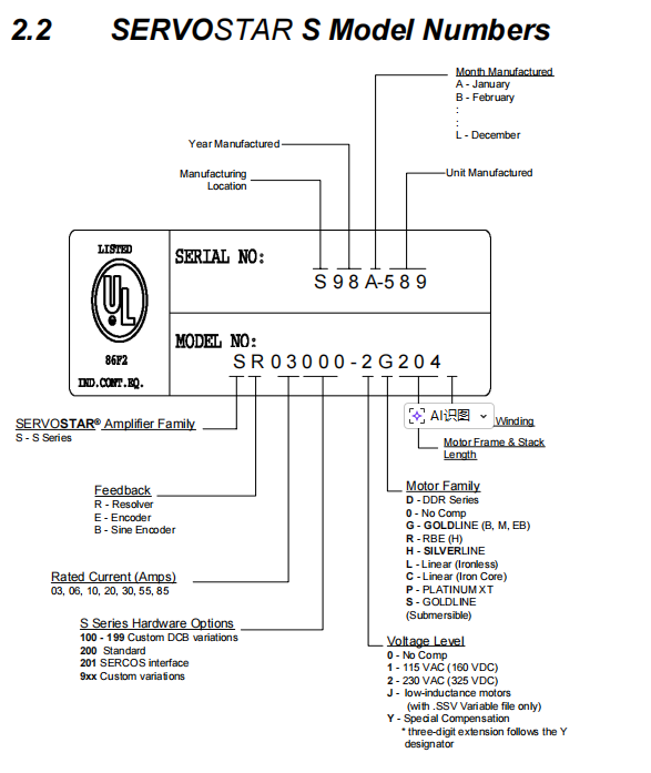
1.2 Model Analysis
Accurately interpreting the model is a prerequisite for selecting and replacing spare parts correctly. The model name of ServoStar S contains rich technical information, such as current level, voltage level, feedback type, and hardware options.
Family Series: Starting with "S" represents the S series.
Rated current: such as 03, 06, 10, 20, 30, 55, 85, representing the continuous current output capability from 3A to 85A, respectively.
Feedback type:
R: Rotating transformer.
E: Encoder.
B: Sine encoder.
voltage level
1:115 VAC (160 VDC)。
2:230 VAC (325 VDC)。
Hardware options: For example, 200 represents the standard version, and 201 represents the SERCOS interface version.
For example, model S R 03 200-2 indicates that the driver belongs to the S series, has a rated current of 3A, uses a rotary transformer feedback, and is suitable for standard version drivers with 230VAC input voltage. By analyzing the model, engineers can quickly determine the key parameters of the drive, avoiding system incompatibility caused by selection errors.
Mechanical installation and environmental considerations
The installation environment of servo drives directly affects their heat dissipation efficiency and electromagnetic compatibility (EMC).
2.1 Installation Space and Direction
The ServoStar S drive is designed for vertical installation to ensure optimal natural convection heat dissipation. According to the manual specifications, at least 63.5mm (2.5 inches) of ventilation space needs to be reserved above and below the drive, and no additional spacing is required laterally. For high current models (such as Sx85), the device is equipped with a built-in cooling fan, and special attention should be paid to not blocking the air inlet and outlet. The driver should be installed on a metal backplate, not only for mechanical stability, but also to achieve high-frequency grounding and reduce electrical noise interference.
2.2 Environmental specifications
Temperature range: Operating temperature is from 0 ° C to 45 ° C (32 ° F to 113 ° F). The storage temperature can reach -20 ° C to 70 ° C. In high temperature environments, the drive power needs to be reduced for use.
Altitude: When the altitude exceeds 3300 feet (1000 meters), a 5% reduction in altitude is required for every 1000 feet increase.
Protection level: This series of products is usually IP20 (open type) and must be installed in a sealed electrical cabinet that meets the final product IP level requirements to prevent dust and moisture.
Electrical wiring and EMC compliance design
Electrical wiring is the most challenging aspect in servo system engineering, directly determining the system's anti-interference ability and operational lifespan.
3.1 Grounding and equipotential connection
Good grounding is the cornerstone of stable system operation.
Safe grounding: All metal components must be connected to a protective grounding (PE) to prevent the risk of electric shock.
High frequency grounding: To suppress high-frequency interference generated by PWM switches, it is necessary to use low impedance flat braided copper tape or copper bars to connect the driver base plate, EMI filter housing, and cabinet grounding bar. Do not rely solely on wires as high-frequency grounding paths, as the high inductance characteristics of wires can significantly reduce the effectiveness of high-frequency filtering.
Star point grounding: It is recommended to adopt the principle of single point grounding, and connect the shielding layers of the motor, driver, and filter to the grounding busbar uniformly.
3.2 Shielding and Wiring Specifications
Power cable: Shielded cable or metal sheathed cable must be used. The shielding layer should be connected in a 360 ° circular manner using shielding clips (such as Phoenix Contact SK series) at the driver end to ensure that noise is bypassed at the source.
Signal cable: The control cable and motor power cable must maintain a minimum distance of 20cm. If crossing is necessary, it should be done at a 90 ° right angle to reduce capacitive coupling.
Feedback cable: The rotary transformer and encoder signals are weak electrical signals that are highly susceptible to interference. It is strictly prohibited to lay them in the same slot as the power line.
3.3 Application of EMI filtering technology
To meet CE certification and industrial environment electromagnetic compatibility standards, EMI filters must be installed on the input power end.
Filter selection: Match the filter according to the Bus Module model. For example, PA08 recommends Filter Concepts SF10 for single-phase and Schaffner FN258-30/07 for three-phase. The filter should be installed at the power inlet, closely attached to the back panel.
Motor output filtering: Although CE compliance is not mandatory, it is recommended to install a common mode choke or output reactor at the motor output end in situations where the motor cable is long (such as over 20 meters) or sensitive to noise, to suppress overcurrent faults and insulation aging caused by long line capacitance effects.
Bus Module and Power Management
The ServoStar S system adopts a modular power supply architecture, with the core component being the Bus Module (PA series).
4.1 Bus Module Function Analysis
The Bus Module is responsible for rectifying AC input into DC bus voltage and providing the logic control power supply (± 15V,+8V) required by the driver.
PA-LM: Only provides logic power supply, suitable for multi axis system expansion.
PA08/14/28/50/75/85: Integrated rectifier unit, DC bus capacitor, and logic power supply. Depending on the current level, it supports single-phase or three-phase input.
4.2 Regenerative braking and energy consumption resistance
When the motor is in power generation mode (such as rapid deceleration, gravity lowering), mechanical energy is converted into electrical energy and fed back to the DC bus, resulting in an increase in bus voltage. If the voltage exceeds the threshold (usually 390VDC), the regenerative resistor built in or externally connected to the Bus Module will be put into operation.
Built in resistor: PA14/28 and other low-power modules have built-in regenerative resistors.
External resistor: PA50/75/85 requires an external regeneration resistor kit (such as ER-20/ER-21).
Safety reminder: Regenerated resistors emit a large amount of heat during operation and must be installed in a well ventilated area away from flammable materials. They should also be equipped with overheat protection relays, which should be connected in series to the main contactor control circuit to prevent the resistor from overheating and causing a fire.
Feedback system configuration and connection
The ServoStar S drive is compatible with multiple feedback devices and supports high-precision position and speed control.
5.1 Rotary Transformer
Rotary transformer is the most robust feedback device in industrial servo.
Principle: Using the principle of transformers, sine and cosine signals are modulated by the relative position changes between the rotor and stator.
Resolution: The drive adopts software R/D conversion technology internally, and the resolution can be automatically adjusted according to the speed limit (VLIM), with a maximum of 16 bits (65536 counts/rev).
Wiring: The C2 connector provides Ref High/Low excitation signals and Sine/Cosine feedback signals. Attention should be paid to impedance matching between the shielding layer grounding and long-distance transmission.
5.2 Digital Encoder
Incremental encoder: outputs A, B, Z, and complementary signals. ServoStar S performs cable breakage detection through hardware circuits.
Phase change initialization: For standard encoders without Hall signals (MENCTYPE 1/2), the driver needs to execute the "Wake&Shake" algorithm when enabled, and determine the magnetic pole position by energizing the lock shaft, which requires the load to allow slight rotation.
Hall signal: used for rough commutation positioning during power on to improve system reliability.
5.3 Sine Encoder
High precision feature: Output 1Vpp sine wave signal, perform 256 times interpolation inside the driver, greatly improving position resolution.
ENDAT protocol: Supports Heidenhain ENDAT encoder, can achieve absolute position memory, and does not require finding the origin when powered on.
Communication configuration and MOTIONLINK software
ServoStar S provides flexible communication interfaces and powerful debugging software.
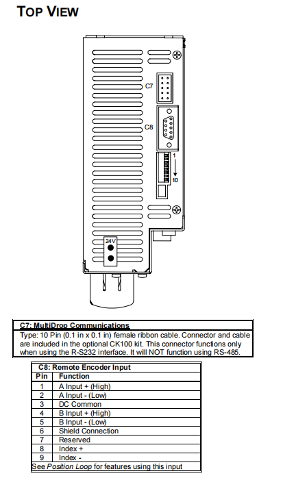
6.1 Hardware interface and address settings
RS-232/RS-485: Serial communication through C1 connector. The DIP switch at the top of the drive is used to set the node address (1-31) and baud rate (9600/19200).
SERCOS interface: For SERCOS versions (model suffix 201), connect through fiber optic ring network. DIP switch sets node address, S9 sets optical power to accommodate different lengths of fiber.
6.2 MOTIONLINK Software Application
MotionLink is a configuration and debugging software based on the Windows platform, which greatly reduces the user's threshold for use.
Startup Wizard: The startup wizard guides users through the process of driver setup, motor selection, operation mode configuration, and self-tuning.
Terminal mode: Provides command-line interface, supports parameter backup and recovery through commands such as SAVE and DUMP, suitable for advanced users for deep debugging.
Oscilloscope function: Built in virtual oscilloscope can capture real-time waveforms such as position, velocity, current, etc., assisting in PID parameter tuning and mechanical resonance analysis.
6.3 Operating Mode (OPMODE)
The driver supports multiple operating modes to adapt to different control requirements:
OPMODE 0/1: Speed control mode (serial/analog).
OPMODE 2/3: Torque control mode (serial/analog).
OPMODE 4: Electronic gear/position following mode, supporting pulse input or external spindle encoder.
OPMODE 8: Position control mode, supporting absolute positioning, relative positioning, and origin reset.
OPMODE 5: SERCOS communication mode.
System debugging, maintenance, and troubleshooting
7.1 Startup Sequence
After power on, the driver performs a self-test. The status display (7-segment digital tube) will sequentially show "8" (self-test) and OPMODE numbers (normal). If "-" is displayed, it indicates that the parameter is not configured. To enable a driver, three conditions must be met: no fault (DRIVE OK), software enabled (SWEN), and hardware enabled (REMOTE).
7.2 FoldBack overload protection mechanism
ServoStar S has intelligent FoldBack protection function.
Driver FoldBack: When the output current exceeds the continuous rated value, the driver allows short-term overload (such as maintaining peak current for 2 seconds), and then decays the current index to the continuous current level to protect the IGBT from overheating.
Motor FoldBack: Set motor thermal model parameters through MFOLD variables to protect motor windings.
7.3 Fault Code Analysis
The driver displays status and returns fault codes through the serial port, which are divided into fatal faults, non fatal faults, and warnings.
Fatal malfunction (requiring power-off reset):
't ': Drive overheating. Check the fan and heat sink.
'o': Overvoltage. Check the regenerative resistance or deceleration slope.
'P': Power level overcurrent or short circuit.
'r' series: Feedback signal loss (encoder/rotary converter disconnection).
Non fatal malfunction:
'H': Motor overheating (temperature control switch disconnected).
'u': Undervoltage.
'J': Speeding.
Troubleshooting process: When a fault occurs, first check the FLTHIST fault history through MotionLink, and locate the problem by combining the error number and possible cause table.
7.4 Firmware Upgrade
ServoStar S supports firmware flashing through serial port. Users can contact technical support to obtain the latest version of firmware to fix bugs or unlock new features.
- YOKOGAWA
- Reliance
- ADVANCED
- SEW
- ProSoft
- WATLOW
- Kongsberg
- FANUC
- VSD
- DCS
- PLC
- man-machine
- Covid-19
- Energy and Gender
- Energy Access
- Renewable Integration
- Energy Subsidies
- Energy and Water
- Net zero emission
- Energy Security
- Critical Minerals
- A-B
- petroleum
- Mine scale
- Sewage treatment
- cement
- architecture
- Industrial information
- New energy
- Automobile market
- electricity
- Construction site
- HIMA
- ABB
- Rockwell
- Schneider Modicon
- Siemens
- xYCOM
- Yaskawa
- Woodward
- BOSCH Rexroth
- MOOG
- General Electric
- American NI
- Rolls-Royce
- CTI
- Honeywell
- EMERSON
- MAN
- GE
- TRICONEX
- Control Wave
- ALSTOM
- AMAT
- STUDER
- KONGSBERG
- MOTOROLA
- DANAHER MOTION
- Bentley
- Galil
- EATON
- MOLEX
- Triconex
- DEIF
- B&W
- ZYGO
- Aerotech
- DANFOSS
- KOLLMORGEN
- Beijer
- Endress+Hauser
- schneider
- Foxboro
- KB
- REXROTH
- YAMAHA
- Johnson
- Westinghouse
- WAGO
- TOSHIBA
- TEKTRONIX
- BENDER
- BMCM
- SMC
- HITACHI
- HIRSCHMANN
- XP POWER
- Baldor
- Meggitt
- SHINKAWA
- Other Brands
- UniOP
- KUKA
- IBA
- Beckhoff
-
Basler Electric DECS-250-CN1SN1N Automatic Voltage Regulator for Generator Excitation Control
-
ADLINK CPCI-6860A - 51-31310-OB10 industrial motherboard CompactPCI SBC
-
ADLINK AmITX-SL-G-H110 - 51-7A104-0A30 Mini-ITX Industrial Motherboard
-
ADLINK PXI-2005-003 - CPCI Industrial PC Data Acquisition Card Multi-Function DAQ
-
ADLINK DININ-814M - 51-14032-0A3D SCSI-100P cable connection Interface Terminal Board
-
ADLINK CPCI-3920NA/C2D15/M1G - 3U CompactPCI Intel Core 2 Duo Single Board Computer
-
ADLINK PCIE-8560 - 51-18014-0A20 Communication Card High Speed DAQ
-
ADLINK PCI-C154+ - Motion Control Card 4-axis Motion Controller Board
-
ADLINK PCI-RTV24 - image capture card Analog Video Frame Grabber
-
ADLINK NuPRO-842LV/P - 51-41360-0B30 Industrial Motherboard CPU Board
-
ADLINK cBP-3208/3208R - CPCI Board 3U 8-Slot CompactPCI Backplane
-
ADLINK PCI-8164 - 4-Axis Motion Controller PCI Card 51-12406-0A40
-
ADLINK PCIe-GIE64+ - 4-CH GigE Vision PoE+ Frame Grabber Video Capture Card
-
ADLINK CPCI-6860 / 6860A - CompactPCI Dual Xeon Single Board Computer
-
ADLINK IEC-915GV - REV 1.1 Industrial motherboard CPU Board
-
ADLINK ND-6520 - Technology RS-232 to RS-422RS-485 Converter NuDAM Module
-
ADLINK RTV-24 / PCI-MP4S - 51-12519-1C30 4-Channel Real Time Video Capture Board
-
ADLINK cPCI-6910 / cPCI-6910AM/M1G - cPCI-6910AM/DXL16/M1G/S80G(G)-3120 BOARD CompactPCI SBC
-
ADLINK NUPRO-A40H - Linghua 51-41807-1A30 Industrial Control Computer Motherboard
-
ADLINK USB-3488A - USB to GPIB INTERFACE USB-3488A(G) Controller Module
-
ADLINK PCI-8134A - motion control card 4-Axis Controller Card
-
ADLINK PCI-7432 - Board 32-Channel input / 32-output Isolated Digital I/O PCI Card
-
ADLINK PCI-8134A - 51-12421-0A10 motion controller card tested
-
ADLINK LPCIe-7230 - 32 CH Isolated Input/output Card 2 Interrupts Low Profile PCIe
-
ADLINK NuPRO-E340 - industrial computer motherboard 51-47807-0A30 PICMG 1.3 SHB
-
ADLINK PCI-7434 - High-speed Digital Acquisition Card 64-CH Isolated DO Card
-
ADLINK NuPRO-E330 - 51-41805-0A20 Indsutrial Board SHB Single Board Computer
-
ADLINK PCI-7248 - OPTO-22 48 CHANNEL DIO DIGITAL TTL/DTL I/O 51-12006-0A40 GP
-
ADLINK PCI-8134 - Motion control card 4-Axis Controller Card
-
ADLINK AMP-208C - Movimiento Control Tarjeta 51-12420-1A20 W/Expansión & Breakout
-
ADLINK PCI-8164 - 51-12406-0A40 PCB Board 4-Axis Motion Controller Card
-
ADLINK DIN-68Y-SGII / DIN-68M-J3A - Terminal Board Connector Interface Block
-
ADLINK PCIe-7432 - Technology 51-18402-0A10 PCIe Card With High Input Range
-
ADLINK PCI-8144 / PCI-8144N - Motion control card 4-Axis Stepper Controller Card
-
ADLINK HSL-HUB3/REPEATER - HIGH SPEED LINK EXTENSION MODULES Distributed Hub Module
-
ADLINK ND-6017 - Data Logging + Acquisition 8CH A/D input Mod NuDAM Module
-
ADLINK LPCIe-7250 - data acquisition card Low Profile 8-CH Relay Output Card
-
ADLINK PCI-7432 - I/O card 64-CH Isolated Digital Input Output PCI Card
-
ADLINK IMB-M43H - industrial control computer motherboard Q87 Chip Micro-ATX
-
ADLINK MP-C154 - Motion control Card 4-Axis Motion Controller Board
-
ADLINK PCI-RTV24 - image capture card Video Frame Grabber Card
-
ADLINK PCI-7250 - 8-CH Relay Output & 8-CH Isolated DI Card
-
ADLINK PCI-6308V - 8-CH 12-Bit Isolated Analog Output PCI Card PCB-I-E-1148=6EX2
-
ADLINK PCI-7248 - capture card 48-CH Opto-22 Compatible DIO Card
-
ADLINK HSL-AI16A02-M-VV - Analog Input Output Distributed Module
-
ADLINK NuPRO-A301 - Rev:1.4 NUPRO-A301 PICMG Full-Size Single Board Computer
-
ADLINK PCI-6208V-GL - 8-CH Voltage Analog Output PCI Card
-
ADLINK PCI-8134A - 51-12421-0A10 4-Axis Motion Controller Card
-
ADLINK MNET-S23 - TECHNOLOGY MNET S23 - SERVO DRIVER CONTROL MODULE
-
ADLINK M-342 - ATX I3 I5 I7 Q67 Industrial Motherboard
-
ADLINK NUPRO-780 - Industrial Motherboard CPU Board PICMG SBC
-
ADLINK MP-C154 / MP-C152 - 4-Axis Motion Control Card Pulse-Train Controller
-
ADLINK NuPRO-935A/LV10B0 - Motherboard 51-41802-0A10 GP w/RAM Industrial Control Board
-
ADLINK MP-C154 - Motion control card 4-Axis Motion Controller Mainboard
-
ADLINK PCI-7250 - PCI Acquisition Card 8-CH Relay Output Isolated DI Card
-
ADLINK ACL-7124 - Technology Inc.24 DIO Card Digital Input Output Card
-
ADLINK PCI-8554 A2 - Timer/Counter Data Acquisition Card
-
ADLINK DIN-825-GP4 - Terminal Block Interface Board Breakout Module
-
ADLINK NuPR0-761 - REV:1.1 Industrial motherboard Full-Size PICMG SBC
-
ADLINK MXE-1401/M8G (G) - Matrix Fanless Embedded Computer Industrial PC
-
ADLINK HSL-DI16DO16-UD-NN - Digital 16 Channel I/O Mod Distributed I/O Module
-
ADLINK ND6520 - NUDAM INTELLIGENT DA&C MODULE RS232-RS-422/RS485 CONVERTOR
-
ADLINK NUPRO-761 - REV:1.1 Industrial Motherboard CPU Board
-
ADLINK AMP-208C - Motion Control Card 51-12420-1A20 DSP-based 8-axis
-
ADLINK NuPRO-A301REV 1.4 - with packaging industrial computer motherboard PICMG SBC
-
ADLINK PCM-9112+ - 51-12300-0A2 industrial motherboard Multi-Function DAQ PC/104 Module
-
ADLINK PCM-7250+ - 8-CH Relay Outputs & 8-CH Isolated DI Module PC/104
-
ADLINK PCI-RTV24 - Image capture card Analog Video Frame Grabber
-
ADLINK PCI-8134 - Motion Controller PCI Card 4-Axis Controller Board
-
ADLINK PCI-7432 - Isolated Digital I/O PCI Card
-
ADLINK PCI-8554 A2 - acquisition card Timer/Counter Card
-
ADLINK PCI-8132 - Rev.A2 2-Axis Servo & Stepper Motion Controller Card
-
ADLINK PCI-8132 - Data Acquisition card 2-Axis Motion Controller Card
-
ADLINK EBP-13E4 - 51-46703-0A30 Industrial Backplane Board Passive Backplane
-
ADLINK PCI-800L - Electronic Card Interface Controller Card
-
ADLINK PCIe-GIE72 - 51-18531-0A10 PCB Board GigE Vision Frame Grabber
-
ADLINK DAQ-2010(G)-OOBO - Simultaneous-Sampling Multi-Function DAQ Card
-
ADLINK PCI-9112 - REV.B1 Multifunction DAQ Card Data Acquisition Card
-
ADLINK PCI-7230 - 51-12003-DA60 32-CH Isolated Digital I/O Card
-
ADLINK PCI-7432 - Data Acquisition Card Isolated Digital I/O PCI Card
-
ADLINK ETX-AT-N270-18/LXE - 51-71111-0A20 ETX CPU Module Motherboard
-
ADLINK HSL-DI32-UD-N - DIGITAL INPUT 32 POINTS MODULE Distributed I/O
-
ADLINK AMP-204C - Motion Control card DSP-Based 4-Axis Advanced Controller
-
ADLINK MNET-4XMOG-0050 - Four-axis Motion Controller Distributed Motion Module
-
ADLINK AMP-204C - Motion control card DSP-Based 4-Axis Pulse-Train Controller
-
ADLINK PCI-7442 - Switch card 64-Channel Datalogging & Acquisition Card
-
ADLINK M-302 - Industrial control motherboard ATX PC Board
-
ADLINK NUPRO-852 / NUPRO-852LV - Industrial motherboard Single Board Computer
-
ADLINK PCI-8134 - REV.B1. 4-Axis Motion Controller Card
-
ADLINK PCI-GIE62 + - 51-18502-0A20 2-CH GigE Vision Frame Grabber PoE Card
-
ADLINK PCI-MPG24 - 51-12523-0B20 MPEG4 Card Video Compression Hardware
-
ADLINK HSL-TB32-M-DIN - 32-CH I/O TERMINAL W/ HSL-AI16AO2-M-VV MODULE
-
ADLINK PCI-M114-GL - PCB Ver 2.1 Motion Controller Axis Card
-
ADLINK IMB-M40H - SYM76996H61 motherboard Industrial Computer Mainboard
-
ADLINK NUPRO-A40H - 51-41807-1A20 industrial control motherboard H61 Chip
-
ADLINK PCI-M114-GL - Axis Card Data Acquisition Card PCB VER2.2 Motion Controller
-
ADLINK PCI-8134 - Motion Controller PCI Card 4-Axis Controller Board
-
ADLINK PCI-8102 - Motion control card 2-Axis Servo & Stepper Controller
-
ADLINK NuPRO-841REV:3.0 - motherboard Industrial Control PC Board
-
ADLINK HSL-TB32-U-DIN REV A1 - Breakout Terminal Board Field I/O Module
-
ADLINK AMP-204C - Motion Control card DSP-Based 4-Axis Pulse-Train Controller
-
ADLINK NUPRO-A40H - 51-41807-1A20 industrial control motherboard H61 PC Board
-
ADLINK PCI-6308A / PCI-6308V - 51-12202-0A50 Isolated Analog Output Card
-
ADLINK AMP-204C - DSP-Based 4-Axis Advanced Pulse-Train Motion Controller
-
ADLINK PCI-7434 - Technology 64-Channel Isolated Digital I/O PCI Cards
-
ADLINK CPCI-6840 / CPCI-6840V / PM16/M1G-12G0 - CompactPCI Single Board Computer CPU Module
-
ADLINK PCIE-GIE74 - Motherboard Video Capture Card 51-18531-0A10 Frame Grabber
-
ADLINK NuPRO-E330 - industrial computer equipment motherboard Control Mainboard
-
ADLINK AMP-208C / 51-12420-1A20 - Motion Control Card W/ Expansion & Breakout Board
-
ADLINK HPCI-14S12U - industrial computer baseboard Passive Backplane 14 Slots
-
ADLINK PCI-8164 - 4-Axis Motion Controller PCI Card W/ 1x Cable, 1x Breakout Box
-
ADLINK PCIe-RTV24 - 51-18016-0A20 Image Acquisition Video Capture Card
-
ADLINK M-342 - 5 PCI ATX Motherboard Industrial PC Mainboard
-
ADLINK PCI-FIW64 - 4/2 Channel IEEE1394B Image Capture Card FireWire Frame Grabber
-
ADLINK PCI-7432 - digital IO card 64-CH Isolated Digital Input Output Card
-
ADLINK 51-12001-0C20 - Circuit Board PCI-7200 Data Acquisition Controller Card
-
ADLINK PXI-3920 - PXI 3U cPCI Industrial Controller Embedded System CPU Board
-
ADLINK NuPRO-841REV:2.0 - motherboard Industrial Control PC Board
-
ADLINK NuPro-E330 - 51-41805-0A20 PCB Industrial Control Computer Motherboard
-
ADLINK PCI-RTV24 - Image capture card Analog Video Frame Grabber
-
ADLINK PCI-7442 - Switch card 64-Channel Datalogging & Acquisition Card
-
ADLINK HPX-13S4 - device baseboard Passive Backplane Riser Card
-
ADLINK PCI-9112 REV A.1 - Multi Function DA&C Board Data Acquisition Card
-
ADLINK PCI-7248 - 51-12006-0A40 Card Control 48-CH Digital I/O Module
-
ADLINK CPCI-6860 / 6860A - motherboard CompactPCI Dual Xeon Single Board Computer
-
ADLINK DPAC-3020-11(G) - Embedded PC Automation Controller Machine Control Board
-
ADLINK NuPRO-841 REV:1.0 - industrial control motherboard CPU Board
-
ADLINK MNET-4XMOG-0050 - Four-axis Motion Controller MNET Motion Control Card

K-JIANG

Add: Jimei North Road, Jimei District, Xiamen, Fujian, China
Tell:+86-15305925923