
K-WANG


Omron C200HX/HG/HE PLC Installation and Configuration Guide
Omron C200HX/HG/HE Programmable Controllers: A Comprehensive Guide to System Architecture, Installation, Deployment, and Maintenance
In the field of industrial automation control, the importance of Programmable Controller (PC or PLC) as the "brain" of the system is self-evident. The C200HX, C200HG, and C200HE series PLCs launched by Omron are widely used in various control systems due to their flexible configuration, powerful processing capabilities, and high reliability. Based on the latest installation guide materials, this article will provide a detailed professional analysis of the system architecture, hardware installation, wiring specifications, and maintenance troubleshooting of this series of PLCs, aiming to provide engineers with a detailed practical reference.
Fundamentals of Control Systems and Working Principles of PLC
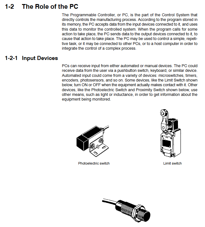
It is crucial to understand the infrastructure of the control system before delving into hardware details. A typical control system not only includes the PLC itself, but also covers the complete hierarchy from the upper computer (such as process control computer, factory computer) to the lower actuators (such as sensors, motors, solenoid valves). PLC plays a core role in this hierarchy, receiving on-site signals through input devices, performing logical operations based on user programs stored in memory, and controlling mechanical actions through output devices.
1. Working cycle of PLC
The operation of PLC is not arbitrary, but follows strict scanning cycles. A complete PC cycle consists of four main stages:
Overseeing: self diagnostic processes such as watchdog timer operations, program memory testing, etc.
Data input/output: Read the input signal and refresh the output signal.
Instruction execution: Execute user program logic.
Peripheral services: handle interactions with programming devices, communication boards, etc.
The total time of this cycle is called the 'cycle time'. For the C200HX series, its basic instruction processing speed can reach 0.1 microseconds, greatly improving the system's real-time response capability. Understanding this mechanism is crucial for designing complex control logic, as the length of the cycle time directly determines the system's response speed to input signals.
System configuration and hardware architecture
The C200HX/HG/HE series PLC adopts modular design, allowing users to flexibly configure the system according to their actual needs. Its basic structure includes a CPU rack, an expansion I/O rack, and various functional units.
1. CPU rack
The CPU rack is the core of the control system, consisting of a CPU motherboard, CPU unit, power unit, and I/O unit.
CPU Unit: C200HX/HG/HE offers multiple models, ranging from entry-level C200HE-CPU11-E/ZE to high-performance C200HX-CPU85-ZE. Different models have differences in program capacity, I/O points, Extended Data Memory (EM), and instruction execution speed. For example, C200HX-CPU85-ZE has up to 63.2K words of user program memory and 16 banks of extended data memory, making it suitable for handling extremely complex control algorithms. The front of the CPU unit integrates indicator lights (RUN, ERR, INH, COMM), memory box slots, DIP switches, as well as peripheral ports and RS-232C ports.
Power supply unit: The power supply unit is installed in the first slot of the base plate and is responsible for supplying power to the system. The models include AC input (such as C200HW-PA204, supporting 100-240VAC wide voltage input) and DC input (such as C200HW-PD024, supporting 24VDC). Some high-end models, such as C200HW-PA209R, offer higher output current (9A) and RUN output contacts, while C200HW-PA204C has a unique "replacement notification function". When the power supply life is about to end, it will alert the user to replace it through an alarm output to avoid accidental shutdown.
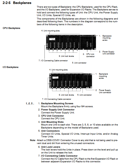
Base board: divided into CPU base board and I/O base board, providing various specifications such as 3 slots, 5 slots, 8 slots, and 10 slots. The connectors on the motherboard are responsible for connecting various units and connecting the expansion rack through I/O connection cables.
2. Expand the I/O rack
In order to meet the demand for a large number of I/O points, the system allows the connection of up to 2 to 3 expansion I/O racks (the specific number depends on the CPU model). The expansion rack is connected to the CPU rack through I/O connection cables (with a total length not exceeding 12 meters), increasing the physical coverage and control scale of the system.
3. Special functional units and networks
In addition to standard I/O units, this series of PLCs supports a wide range of special I/O units, such as analog input/output units, temperature control units, high-speed counting units, position control units, etc. In terms of network communication, it supports multiple network architectures such as SYSMAC LINK, SYSMAC NET, Host Link, DeviceNet, etc., making it easy to build hierarchical distributed control systems.
Installation environment and physical deployment
Correct installation is a prerequisite for ensuring the long-term stable operation of PLC. There are strict regulations in the installation guide that must be followed.
1. Environmental requirements
The working environment of PLC is directly related to its lifespan. Installation must be avoided in the following environments:
Direct sunlight, temperature or humidity exceeding specification range (operating temperature: 0 to 55 ° C, humidity: 10% to 90% without condensation).
There are corrosive, flammable gases or large amounts of dust (especially iron powder), salts present.
Strong electromagnetic interference or vibration source.
The design of control cabinets is crucial to cope with harsh environments. It is necessary to maintain ventilation inside the cabinet, install cooling fans if necessary, and ensure that the cabinet meets NEMA standards to prevent dust and water.
2. Installation details
Installation direction: The PLC must be installed vertically to ensure a good heat dissipation duct. Do not install horizontally or upside down.
Spacing: In order to facilitate wiring and heat dissipation, at least 20mm of space should be reserved above and below the rack; It is recommended to maintain a spacing of 70mm to 120mm between racks.
DIN rail installation: Supports standard DIN rail installation, but in environments with high vibration, it is recommended to use screws to directly fix to the base plate to improve shock resistance.
Anti static: Before touching the unit, be sure to contact a grounded metal object to release static electricity and prevent electrostatic discharge from damaging sensitive semiconductor components.
Wiring specifications and anti-interference measures
The quality of wiring directly determines the accuracy of signal transmission. Incorrect wiring can not only cause equipment damage, but also potentially lead to safety accidents.
1. Power wiring
AC power unit: When wiring, attention should be paid to selecting the voltage terminal (for early models), while modern wide voltage models (such as PA204) do not require manual switching. Be sure to use crimping terminals and do not directly connect bare wires. The ground (GR) terminal must be connected to a grounding electrode below 100 Ω to protect equipment and personnel safety. The LG terminal is a noise filtering neutral terminal, usually short circuited to the GR when interference is severe.
DC power unit: When wiring, it is necessary to distinguish between positive and negative poles. To comply with the EC directive, DC power supplies should have reinforced insulation or double insulation.
2. I/O wiring
Terminal tightening: The torque of the wiring screw should be controlled at 0.8 N · m. Too loose can lead to poor contact, while too tight may damage the terminals.
Label management: During the wiring process, keep the protective label at the top of the unit to prevent wire shavings from falling into the interior of the unit; After wiring is completed, be sure to remove the label to avoid affecting heat dissipation.
Cable isolation: I/O signal lines and power lines should be routed separately as much as possible. If parallel laying is necessary, the spacing should be kept at least 300mm. For AC input/output lines, it is recommended to use shielded cables and ground the shielding layer.
3. Noise countermeasures
The industrial site is filled with electromagnetic noise. For inductive loads such as relays and solenoid valves, surge suppressors (such as RC circuits, diodes, or varistors) must be connected in parallel at both ends of the load to absorb the reverse electromotive force generated at the moment of disconnection and prevent damage to the PLC output contacts. For the relay output of high-frequency switches, attention should be paid to their electrical life limit (about 300000 cycles), and intermediate relays should be used for isolation if necessary.
Programming equipment and system debugging
After the system is built, it needs to be debugged through programming equipment. C200HX/HG/HE supports two main programming methods:
Programming console: such as C200H-PRO27-E, connected to the peripheral port of the CPU, suitable for simple program modification and monitoring on site.
CX Programmer software: runs on IBM PC/AT compatible machines, connected through RS-232C ports or dedicated cables (such as CQM1-CIF02), providing a graphical programming interface and powerful debugging capabilities.
When powering on for the first time, check if the programming controller's display is normal and enter the correct password (Clear+Monitor key). Before downloading the program, make sure the CPU is in Program mode to avoid unexpected conflicts with running programs.
Maintenance, troubleshooting, and component replacement
Although PLC is sturdy and durable, regular inspection and maintenance are essential. The manual provides a detailed process for maintenance and troubleshooting.
1. Troubleshooting
PLC has powerful self diagnostic function. Users should first observe the status of the indicator lights on the CPU panel:
RUN light not on: Check if the program is missing the END command or if there is a serious hardware error.
ERR light flashing: indicates a non fatal error (such as low battery voltage), the system can continue to operate, but it needs to be dealt with in a timely manner.
ERR light constantly on: indicates a fatal error, the CPU has stopped running, and a user program or hardware malfunction needs to be checked.
INH light on: indicates that the output disable bit (SR 25215) is set and all outputs are forcibly cut off.
2. Component replacement
Fuse replacement: Some output units (such as OD411, OA221) are equipped with fuses. If the fuse indicator light is on, it indicates that there is a short circuit on the load side. Before replacement, the power must be cut off and UL/CSA certified fuses recommended by the manufacturer must be used.
Relay replacement: For relay output units (such as OC221), relays are vulnerable parts. If adhesion or poor contact is found, the unit housing should be opened after power failure, and a new relay (model G6B-1174P-FD-US-M) should be replaced with the accompanying relay extractor.
Battery replacement: The battery (C200H-BAT09) is used to maintain data in RAM during power outages. When the ERR light flashes and the programmer displays "BATT FAIL", the battery must be replaced within one week. The replacement process should be completed within 5 minutes of power on or power-off to prevent data loss. The normal service life is about 5 years (25 ° C).
3. Regular inspections
It is recommended to conduct regular inspections every 6 months to 1 year. The inspection items include: whether the power supply voltage fluctuation is within the allowable range, whether the terminal screws are loose, whether there is dust accumulation, etc. For power units (PA204C) with "replacement notification function", when the display "0.0" and "A02" alternate flashing or the alarm output is turned off, the power module must be replaced within 6 months.
- YOKOGAWA
- Reliance
- ADVANCED
- SEW
- ProSoft
- WATLOW
- Kongsberg
- FANUC
- VSD
- DCS
- PLC
- man-machine
- Covid-19
- Energy and Gender
- Energy Access
- Renewable Integration
- Energy Subsidies
- Energy and Water
- Net zero emission
- Energy Security
- Critical Minerals
- A-B
- petroleum
- Mine scale
- Sewage treatment
- cement
- architecture
- Industrial information
- New energy
- Automobile market
- electricity
- Construction site
- HIMA
- ABB
- Rockwell
- Schneider Modicon
- Siemens
- xYCOM
- Yaskawa
- Woodward
- BOSCH Rexroth
- MOOG
- General Electric
- American NI
- Rolls-Royce
- CTI
- Honeywell
- EMERSON
- MAN
- GE
- TRICONEX
- Control Wave
- ALSTOM
- AMAT
- STUDER
- KONGSBERG
- MOTOROLA
- DANAHER MOTION
- Bentley
- Galil
- EATON
- MOLEX
- Triconex
- DEIF
- B&W
- ZYGO
- Aerotech
- DANFOSS
- KOLLMORGEN
- Beijer
- Endress+Hauser
- schneider
- Foxboro
- KB
- REXROTH
- YAMAHA
- Johnson
- Westinghouse
- WAGO
- TOSHIBA
- TEKTRONIX
- BENDER
- BMCM
- SMC
- HITACHI
- HIRSCHMANN
- XP POWER
- Baldor
- Meggitt
- SHINKAWA
- Other Brands
- UniOP
- KUKA
- IBA
- Beckhoff
-
Basler Electric DECS-250-CN1SN1N Automatic Voltage Regulator for Generator Excitation Control
-
ADLINK CPCI-6860A - 51-31310-OB10 industrial motherboard CompactPCI SBC
-
ADLINK AmITX-SL-G-H110 - 51-7A104-0A30 Mini-ITX Industrial Motherboard
-
ADLINK PXI-2005-003 - CPCI Industrial PC Data Acquisition Card Multi-Function DAQ
-
ADLINK DININ-814M - 51-14032-0A3D SCSI-100P cable connection Interface Terminal Board
-
ADLINK CPCI-3920NA/C2D15/M1G - 3U CompactPCI Intel Core 2 Duo Single Board Computer
-
ADLINK PCIE-8560 - 51-18014-0A20 Communication Card High Speed DAQ
-
ADLINK PCI-C154+ - Motion Control Card 4-axis Motion Controller Board
-
ADLINK PCI-RTV24 - image capture card Analog Video Frame Grabber
-
ADLINK NuPRO-842LV/P - 51-41360-0B30 Industrial Motherboard CPU Board
-
ADLINK cBP-3208/3208R - CPCI Board 3U 8-Slot CompactPCI Backplane
-
ADLINK PCI-8164 - 4-Axis Motion Controller PCI Card 51-12406-0A40
-
ADLINK PCIe-GIE64+ - 4-CH GigE Vision PoE+ Frame Grabber Video Capture Card
-
ADLINK CPCI-6860 / 6860A - CompactPCI Dual Xeon Single Board Computer
-
ADLINK IEC-915GV - REV 1.1 Industrial motherboard CPU Board
-
ADLINK ND-6520 - Technology RS-232 to RS-422RS-485 Converter NuDAM Module
-
ADLINK RTV-24 / PCI-MP4S - 51-12519-1C30 4-Channel Real Time Video Capture Board
-
ADLINK cPCI-6910 / cPCI-6910AM/M1G - cPCI-6910AM/DXL16/M1G/S80G(G)-3120 BOARD CompactPCI SBC
-
ADLINK NUPRO-A40H - Linghua 51-41807-1A30 Industrial Control Computer Motherboard
-
ADLINK USB-3488A - USB to GPIB INTERFACE USB-3488A(G) Controller Module
-
ADLINK PCI-8134A - motion control card 4-Axis Controller Card
-
ADLINK PCI-7432 - Board 32-Channel input / 32-output Isolated Digital I/O PCI Card
-
ADLINK PCI-8134A - 51-12421-0A10 motion controller card tested
-
ADLINK LPCIe-7230 - 32 CH Isolated Input/output Card 2 Interrupts Low Profile PCIe
-
ADLINK NuPRO-E340 - industrial computer motherboard 51-47807-0A30 PICMG 1.3 SHB
-
ADLINK PCI-7434 - High-speed Digital Acquisition Card 64-CH Isolated DO Card
-
ADLINK NuPRO-E330 - 51-41805-0A20 Indsutrial Board SHB Single Board Computer
-
ADLINK PCI-7248 - OPTO-22 48 CHANNEL DIO DIGITAL TTL/DTL I/O 51-12006-0A40 GP
-
ADLINK PCI-8134 - Motion control card 4-Axis Controller Card
-
ADLINK AMP-208C - Movimiento Control Tarjeta 51-12420-1A20 W/Expansión & Breakout
-
ADLINK PCI-8164 - 51-12406-0A40 PCB Board 4-Axis Motion Controller Card
-
ADLINK DIN-68Y-SGII / DIN-68M-J3A - Terminal Board Connector Interface Block
-
ADLINK PCIe-7432 - Technology 51-18402-0A10 PCIe Card With High Input Range
-
ADLINK PCI-8144 / PCI-8144N - Motion control card 4-Axis Stepper Controller Card
-
ADLINK HSL-HUB3/REPEATER - HIGH SPEED LINK EXTENSION MODULES Distributed Hub Module
-
ADLINK ND-6017 - Data Logging + Acquisition 8CH A/D input Mod NuDAM Module
-
ADLINK LPCIe-7250 - data acquisition card Low Profile 8-CH Relay Output Card
-
ADLINK PCI-7432 - I/O card 64-CH Isolated Digital Input Output PCI Card
-
ADLINK IMB-M43H - industrial control computer motherboard Q87 Chip Micro-ATX
-
ADLINK MP-C154 - Motion control Card 4-Axis Motion Controller Board
-
ADLINK PCI-RTV24 - image capture card Video Frame Grabber Card
-
ADLINK PCI-7250 - 8-CH Relay Output & 8-CH Isolated DI Card
-
ADLINK PCI-6308V - 8-CH 12-Bit Isolated Analog Output PCI Card PCB-I-E-1148=6EX2
-
ADLINK PCI-7248 - capture card 48-CH Opto-22 Compatible DIO Card
-
ADLINK HSL-AI16A02-M-VV - Analog Input Output Distributed Module
-
ADLINK NuPRO-A301 - Rev:1.4 NUPRO-A301 PICMG Full-Size Single Board Computer
-
ADLINK PCI-6208V-GL - 8-CH Voltage Analog Output PCI Card
-
ADLINK PCI-8134A - 51-12421-0A10 4-Axis Motion Controller Card
-
ADLINK MNET-S23 - TECHNOLOGY MNET S23 - SERVO DRIVER CONTROL MODULE
-
ADLINK M-342 - ATX I3 I5 I7 Q67 Industrial Motherboard
-
ADLINK NUPRO-780 - Industrial Motherboard CPU Board PICMG SBC
-
ADLINK MP-C154 / MP-C152 - 4-Axis Motion Control Card Pulse-Train Controller
-
ADLINK NuPRO-935A/LV10B0 - Motherboard 51-41802-0A10 GP w/RAM Industrial Control Board
-
ADLINK MP-C154 - Motion control card 4-Axis Motion Controller Mainboard
-
ADLINK PCI-7250 - PCI Acquisition Card 8-CH Relay Output Isolated DI Card
-
ADLINK ACL-7124 - Technology Inc.24 DIO Card Digital Input Output Card
-
ADLINK PCI-8554 A2 - Timer/Counter Data Acquisition Card
-
ADLINK DIN-825-GP4 - Terminal Block Interface Board Breakout Module
-
ADLINK NuPR0-761 - REV:1.1 Industrial motherboard Full-Size PICMG SBC
-
ADLINK MXE-1401/M8G (G) - Matrix Fanless Embedded Computer Industrial PC
-
ADLINK HSL-DI16DO16-UD-NN - Digital 16 Channel I/O Mod Distributed I/O Module
-
ADLINK ND6520 - NUDAM INTELLIGENT DA&C MODULE RS232-RS-422/RS485 CONVERTOR
-
ADLINK NUPRO-761 - REV:1.1 Industrial Motherboard CPU Board
-
ADLINK AMP-208C - Motion Control Card 51-12420-1A20 DSP-based 8-axis
-
ADLINK NuPRO-A301REV 1.4 - with packaging industrial computer motherboard PICMG SBC
-
ADLINK PCM-9112+ - 51-12300-0A2 industrial motherboard Multi-Function DAQ PC/104 Module
-
ADLINK PCM-7250+ - 8-CH Relay Outputs & 8-CH Isolated DI Module PC/104
-
ADLINK PCI-RTV24 - Image capture card Analog Video Frame Grabber
-
ADLINK PCI-8134 - Motion Controller PCI Card 4-Axis Controller Board
-
ADLINK PCI-7432 - Isolated Digital I/O PCI Card
-
ADLINK PCI-8554 A2 - acquisition card Timer/Counter Card
-
ADLINK PCI-8132 - Rev.A2 2-Axis Servo & Stepper Motion Controller Card
-
ADLINK PCI-8132 - Data Acquisition card 2-Axis Motion Controller Card
-
ADLINK EBP-13E4 - 51-46703-0A30 Industrial Backplane Board Passive Backplane
-
ADLINK PCI-800L - Electronic Card Interface Controller Card
-
ADLINK PCIe-GIE72 - 51-18531-0A10 PCB Board GigE Vision Frame Grabber
-
ADLINK DAQ-2010(G)-OOBO - Simultaneous-Sampling Multi-Function DAQ Card
-
ADLINK PCI-9112 - REV.B1 Multifunction DAQ Card Data Acquisition Card
-
ADLINK PCI-7230 - 51-12003-DA60 32-CH Isolated Digital I/O Card
-
ADLINK PCI-7432 - Data Acquisition Card Isolated Digital I/O PCI Card
-
ADLINK ETX-AT-N270-18/LXE - 51-71111-0A20 ETX CPU Module Motherboard
-
ADLINK HSL-DI32-UD-N - DIGITAL INPUT 32 POINTS MODULE Distributed I/O
-
ADLINK AMP-204C - Motion Control card DSP-Based 4-Axis Advanced Controller
-
ADLINK MNET-4XMOG-0050 - Four-axis Motion Controller Distributed Motion Module
-
ADLINK AMP-204C - Motion control card DSP-Based 4-Axis Pulse-Train Controller
-
ADLINK PCI-7442 - Switch card 64-Channel Datalogging & Acquisition Card
-
ADLINK M-302 - Industrial control motherboard ATX PC Board
-
ADLINK NUPRO-852 / NUPRO-852LV - Industrial motherboard Single Board Computer
-
ADLINK PCI-8134 - REV.B1. 4-Axis Motion Controller Card
-
ADLINK PCI-GIE62 + - 51-18502-0A20 2-CH GigE Vision Frame Grabber PoE Card
-
ADLINK PCI-MPG24 - 51-12523-0B20 MPEG4 Card Video Compression Hardware
-
ADLINK HSL-TB32-M-DIN - 32-CH I/O TERMINAL W/ HSL-AI16AO2-M-VV MODULE
-
ADLINK PCI-M114-GL - PCB Ver 2.1 Motion Controller Axis Card
-
ADLINK IMB-M40H - SYM76996H61 motherboard Industrial Computer Mainboard
-
ADLINK NUPRO-A40H - 51-41807-1A20 industrial control motherboard H61 Chip
-
ADLINK PCI-M114-GL - Axis Card Data Acquisition Card PCB VER2.2 Motion Controller
-
ADLINK PCI-8134 - Motion Controller PCI Card 4-Axis Controller Board
-
ADLINK PCI-8102 - Motion control card 2-Axis Servo & Stepper Controller
-
ADLINK NuPRO-841REV:3.0 - motherboard Industrial Control PC Board
-
ADLINK HSL-TB32-U-DIN REV A1 - Breakout Terminal Board Field I/O Module
-
ADLINK AMP-204C - Motion Control card DSP-Based 4-Axis Pulse-Train Controller
-
ADLINK NUPRO-A40H - 51-41807-1A20 industrial control motherboard H61 PC Board
-
ADLINK PCI-6308A / PCI-6308V - 51-12202-0A50 Isolated Analog Output Card
-
ADLINK AMP-204C - DSP-Based 4-Axis Advanced Pulse-Train Motion Controller
-
ADLINK PCI-7434 - Technology 64-Channel Isolated Digital I/O PCI Cards
-
ADLINK CPCI-6840 / CPCI-6840V / PM16/M1G-12G0 - CompactPCI Single Board Computer CPU Module
-
ADLINK PCIE-GIE74 - Motherboard Video Capture Card 51-18531-0A10 Frame Grabber
-
ADLINK NuPRO-E330 - industrial computer equipment motherboard Control Mainboard
-
ADLINK AMP-208C / 51-12420-1A20 - Motion Control Card W/ Expansion & Breakout Board
-
ADLINK HPCI-14S12U - industrial computer baseboard Passive Backplane 14 Slots
-
ADLINK PCI-8164 - 4-Axis Motion Controller PCI Card W/ 1x Cable, 1x Breakout Box
-
ADLINK PCIe-RTV24 - 51-18016-0A20 Image Acquisition Video Capture Card
-
ADLINK M-342 - 5 PCI ATX Motherboard Industrial PC Mainboard
-
ADLINK PCI-FIW64 - 4/2 Channel IEEE1394B Image Capture Card FireWire Frame Grabber
-
ADLINK PCI-7432 - digital IO card 64-CH Isolated Digital Input Output Card
-
ADLINK 51-12001-0C20 - Circuit Board PCI-7200 Data Acquisition Controller Card
-
ADLINK PXI-3920 - PXI 3U cPCI Industrial Controller Embedded System CPU Board
-
ADLINK NuPRO-841REV:2.0 - motherboard Industrial Control PC Board
-
ADLINK NuPro-E330 - 51-41805-0A20 PCB Industrial Control Computer Motherboard
-
ADLINK PCI-RTV24 - Image capture card Analog Video Frame Grabber
-
ADLINK PCI-7442 - Switch card 64-Channel Datalogging & Acquisition Card
-
ADLINK HPX-13S4 - device baseboard Passive Backplane Riser Card
-
ADLINK PCI-9112 REV A.1 - Multi Function DA&C Board Data Acquisition Card
-
ADLINK PCI-7248 - 51-12006-0A40 Card Control 48-CH Digital I/O Module
-
ADLINK CPCI-6860 / 6860A - motherboard CompactPCI Dual Xeon Single Board Computer
-
ADLINK DPAC-3020-11(G) - Embedded PC Automation Controller Machine Control Board
-
ADLINK NuPRO-841 REV:1.0 - industrial control motherboard CPU Board
-
ADLINK MNET-4XMOG-0050 - Four-axis Motion Controller MNET Motion Control Card

K-JIANG

Add: Jimei North Road, Jimei District, Xiamen, Fujian, China
Tell:+86-15305925923