
K-WANG


Kongsberg C-series Cutting System: Operation, Maintenance, and Tool Technical Guide
Kongsberg C-series Cutting System: Operation, Maintenance, and Tool Technical Guide
The Kongsberg C-series cutting system represents an integrated model of modern digital cutting and milling technology. Its user manual is not only an operational guide, but also a systematic technical blueprint for achieving efficient, safe, and precise production. This article will conduct an in-depth technical review of the Kongsberg C series from five dimensions: system architecture, security core, operation process, tool system, and maintenance strategy. The aim is to provide equipment operators, maintenance engineers, and production managers with a professional reference that goes beyond basic operations and combines theory and practice.
System architecture and core components: the cornerstone of precision manufacturing
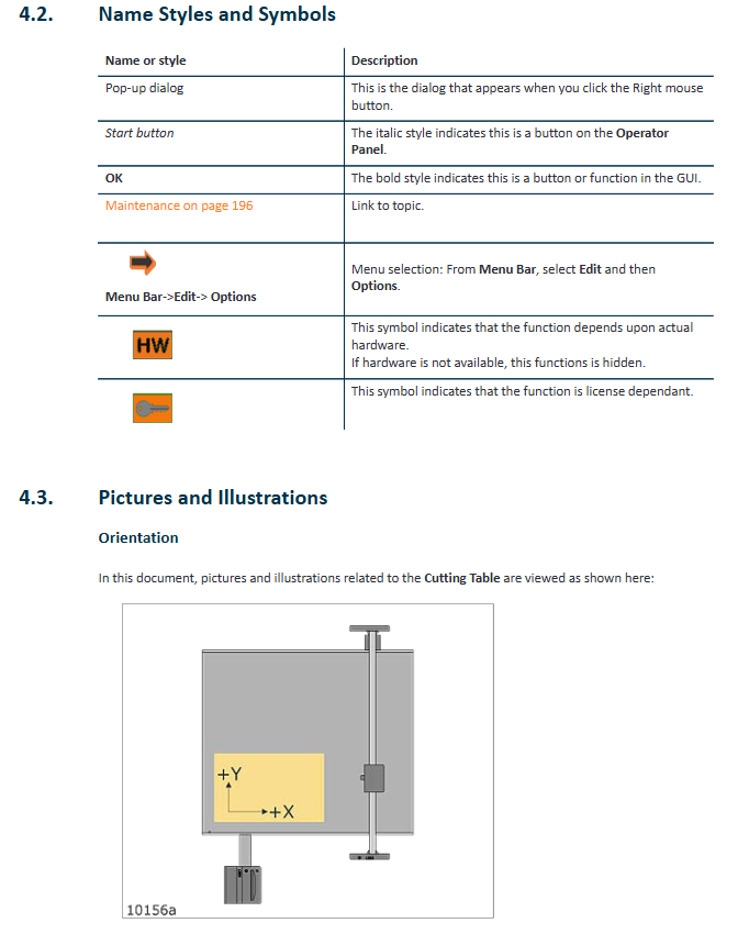
The design of Kongsberg C-series cutting system integrates multiple technologies including mechanical, electrical, pneumatic, and software control. Its main structure is clear and definite: the sturdy cutting table is the work platform; The crossbeam is erected on the platform, carrying the Y-direction sliding seat to move along the X-axis; A tool head is installed on the Y-axis slide to achieve movement in the Y-axis direction and lifting in the Z-axis direction. This three-axis linkage architecture constitutes the core of system motion.
The operation interface is driven by the front-end PC and i-cut Production Console (iPC) software, integrating full process control from job creation, path planning to production execution. The operation station is the core of human-computer interaction, integrating the main power switch, emergency stop button, joystick, operation panel, and optional foot switch. The operation panel buttons such as "servo power", "start", "pause", "vacuum switch", etc. provide direct and fast physical control access. For models equipped with multifunctional extensions, such as systems with conveyor belts, their control logic (such as conveyor belt feeding and vacuum partition control) has been deeply integrated into iPC software and hardware interaction. The pneumatic system of the system provides stable and clean compressed air for pneumatic tools such as fixtures and blowing air. Pressure setting and monitoring are prerequisites for ensuring the normal operation of the tools.
Safety regulations: unbreakable operating red lines
Safety is the primary consideration in the design of Kongsberg C-series, and the detailed safety regulations in the manual constitute an insurmountable red line for operation. The system adopts multi-level protection: the emergency stop button is distributed and can instantly cut off the servo power supply; Yellow/black warning tape delineates hazardous areas and restricts unauthorized personnel from entering; The DynaGuard safety light curtain system constitutes an active protective barrier, and any action that crosses the light curtain will trigger emergency braking. For high-speed rotating milling units, the warning lights equipped not only indicate the operating status, but also continuously flash until the spindle comes to a complete stop after shutdown, forcing the operator to wait for a safe shutdown time of more than 4 seconds.
Safety responsibilities are clearly defined: manufacturers are responsible for the compliance of the equipment itself; Owners need to ensure personnel training, compliant use, and regular maintenance; The operator must follow the regulations and ensure that the machine is in good condition. Potential risks are clearly marked, such as high-pressure areas, laser radiation points, moving parts compression areas, and sharp tool areas, and corresponding symbols such as "Do not touch", "Wear goggles", "Beware of cuts", etc. Special risks such as debris splashing, tool breakage, tool ejection during milling operations, and residual risks of embedded materials after V-shaped or long tool breakage require operators to wear protective goggles throughout the entire process. The recommended use of personal protective equipment such as reflective clothing highlights the importance placed on comprehensive occupational health risks such as noise and dust. Any use that bypasses security systems, operates with defects, or has unintended purposes is clearly defined as improper operation and may result in serious consequences.
Operation process: Standardized path from startup to efficient production
The operation of the system follows a rigorous standardized process to ensure the reliability and repeatability of each production start-up. The startup sequence has been slightly adjusted due to software version updates, but the core logic remains the same: first, start the front-end PC and iPC software; Next, turn on the main power supply of the cutting table; Subsequently, reset the safety system and enable the servo power supply through the operation panel; Finally, perform the 'zeroing' operation to return all axes of the machine to the mechanical origin and complete initialization. Homework preparation is the key to successful production, including: creating homework through iPC, setting layers and tool paths, configuring production parameters (such as number of copies, quality priority), selecting reference points and positioning, setting step repetition, configuring registration methods (such as using positioning rulers or cameras), setting material handling plans and tool head parking positions. The selection of vacuum zone directly affects the material fixation effect, and requires precise configuration according to the material size. If necessary, intelligent vacuum control or physical shielding plates can be used to optimize the adsorption force. Before executing the task, it is necessary to confirm again that the safety system has been reset, and perform bench benchmark calibration as needed to update the tool height measurement value. During the production process, monitoring the system status (such as servo power indicators, warning lights) and standard recovery steps for responding to safety interruptions constitute essential skills for operators.
Tool System: The Essence of Configuration, Adjustment, and Application of Diversified Tools
The strong adaptability of Kongsberg C series comes from its modular and multifunctional tool system. The tools are mainly installed in positions P1 and P2, while some specialized tools such as laser pointers, measuring feet, and cameras have fixed installation positions.
Tool configuration and adjustment are core skills. Each tool needs to undergo systematic calibration: adjusting the tool hysteresis ensures that the direction of the rotating tool tip is tangential to the direction of motion; The height of the tool is automatically measured by the measuring station, but bias values can be added based on material properties. For tools such as perforation wheels, attention should be paid to their directional influence on the measuring station; Adjust the rotation angle to ensure precise cutting of the blade into the material; Center offset adjustment ensures that the center of the tool coincides with the center of the motion path; The tool bias unifies the spatial coordinates of the laser pointer, camera, and actual cutting point. These adjustments can be completed through software guided wizard programs or manually fine tuned based on experience.
The types of tools and specialized application technologies reflect the professionalism of the system:
V-shaped cutter and variable angle unit: used for making folding notches or V-shaped incisions. The key parameters include incision depth, width offset (used to adjust the distance between the bottom of two incisions to optimize the folding angle), and waste cutting (used to clean the uncut material in the middle). The variable angle unit can achieve dynamic angle adjustment from 0 ° to 60 °, expanding its application range. However, its working area may be limited due to tool extension and angle, and the system will automatically calculate and prompt.
Heavy duty unit and its derivatives: integrates various tools such as high-pressure indentation wheel (diameter 150mm), V-knife, heavy-duty cutter, perforation wheel, chamfering knife, etc. The dual type unit can simultaneously install two tools (such as indentation wheel and perforation wheel), significantly improving efficiency. Its installation adopts a new fixing method of pins and locking pins, which has higher reliability.
High power milling unit: equipped with a high-speed spindle (up to 60000 RPM) for milling hard materials. Its operation involves spindle preheating, speed limitation (especially for unbalanced tools), cooling system monitoring, vacuum hood cleaning and height adjustment, as well as strict procedures for tool clamping and replacement. The coolant system (such as LubriCool) can improve lubrication and chip removal for specific materials.
Special cutting tools: including vibration cutting knives, high-frequency vibration cutting knives, RM knives, high force knives, etching knives, cutting knives, rolling cutting knives, braille point cutting knives, corrugated special knives, etc., each with its own material adaptability, cutting depth, and operating precautions. For example, the rolling cutter needs to be cleaned regularly to prevent dust from entering; The braille dot tool needs to be coordinated with the milling unit to complete the two processes of drilling and embedding the sphere.
Measurement and positioning tools: measuring feet are used to automatically measure material thickness and calibrate measurement stations; Laser indicators are used for positioning and auxiliary adjustment; The tool head camera is used for high-precision registration, especially when combined with the bottom camera to achieve double-sided processing.
Maintenance and upkeep: the lifeline for ensuring long-term stable operation
A comprehensive maintenance plan is the lifeline for extending equipment lifespan and ensuring machining accuracy. Daily maintenance focuses on cleaning and visual inspection: cleaning cutting pads, checking the vacuum system, and paying attention to the status of cutting tools and vacuum hoods. Weekly maintenance requires cleaning the guide rails and bearings, lightly applying lubricating oil, checking the cleanliness of the safety light curtain lens, and verifying the automatic drainage function of the air-water separator. Monthly maintenance involves deeper mechanical maintenance: applying lubricating grease to the gears through a dedicated oil gun; Apply lubricating grease to the rack with a soft brush. For systems equipped with conveyor belts, attention should also be paid to adjusting the tension of the conveyor belt. All maintenance work must be carried out with the main power disconnected, strictly following safety regulations.
- YOKOGAWA
- Reliance
- ADVANCED
- SEW
- ProSoft
- WATLOW
- Kongsberg
- FANUC
- VSD
- DCS
- PLC
- man-machine
- Covid-19
- Energy and Gender
- Energy Access
- Renewable Integration
- Energy Subsidies
- Energy and Water
- Net zero emission
- Energy Security
- Critical Minerals
- A-B
- petroleum
- Mine scale
- Sewage treatment
- cement
- architecture
- Industrial information
- New energy
- Automobile market
- electricity
- Construction site
- HIMA
- ABB
- Rockwell
- Schneider Modicon
- Siemens
- xYCOM
- Yaskawa
- Woodward
- BOSCH Rexroth
- MOOG
- General Electric
- American NI
- Rolls-Royce
- CTI
- Honeywell
- EMERSON
- MAN
- GE
- TRICONEX
- Control Wave
- ALSTOM
- AMAT
- STUDER
- KONGSBERG
- MOTOROLA
- DANAHER MOTION
- Bentley
- Galil
- EATON
- MOLEX
- Triconex
- DEIF
- B&W
- ZYGO
- Aerotech
- DANFOSS
- KOLLMORGEN
- Beijer
- Endress+Hauser
- schneider
- Foxboro
- KB
- REXROTH
- YAMAHA
- Johnson
- Westinghouse
- WAGO
- TOSHIBA
- TEKTRONIX
- BENDER
- BMCM
- SMC
- HITACHI
- HIRSCHMANN
- XP POWER
- Baldor
- Meggitt
- SHINKAWA
- Other Brands
- UniOP
- KUKA
- IBA
- Beckhoff
-
ADLINK CPCI-6860A - 51-31310-OB10 industrial motherboard CompactPCI SBC
-
ADLINK AmITX-SL-G-H110 - 51-7A104-0A30 Mini-ITX Industrial Motherboard
-
ADLINK PXI-2005-003 - CPCI Industrial PC Data Acquisition Card Multi-Function DAQ
-
ADLINK DININ-814M - 51-14032-0A3D SCSI-100P cable connection Interface Terminal Board
-
ADLINK CPCI-3920NA/C2D15/M1G - 3U CompactPCI Intel Core 2 Duo Single Board Computer
-
ADLINK PCIE-8560 - 51-18014-0A20 Communication Card High Speed DAQ
-
ADLINK PCI-C154+ - Motion Control Card 4-axis Motion Controller Board
-
ADLINK PCI-RTV24 - image capture card Analog Video Frame Grabber
-
ADLINK NuPRO-842LV/P - 51-41360-0B30 Industrial Motherboard CPU Board
-
ADLINK cBP-3208/3208R - CPCI Board 3U 8-Slot CompactPCI Backplane
-
ADLINK PCI-8164 - 4-Axis Motion Controller PCI Card 51-12406-0A40
-
ADLINK PCIe-GIE64+ - 4-CH GigE Vision PoE+ Frame Grabber Video Capture Card
-
ADLINK CPCI-6860 / 6860A - CompactPCI Dual Xeon Single Board Computer
-
ADLINK IEC-915GV - REV 1.1 Industrial motherboard CPU Board
-
ADLINK ND-6520 - Technology RS-232 to RS-422RS-485 Converter NuDAM Module
-
ADLINK RTV-24 / PCI-MP4S - 51-12519-1C30 4-Channel Real Time Video Capture Board
-
ADLINK cPCI-6910 / cPCI-6910AM/M1G - cPCI-6910AM/DXL16/M1G/S80G(G)-3120 BOARD CompactPCI SBC
-
ADLINK NUPRO-A40H - Linghua 51-41807-1A30 Industrial Control Computer Motherboard
-
ADLINK USB-3488A - USB to GPIB INTERFACE USB-3488A(G) Controller Module
-
ADLINK PCI-8134A - motion control card 4-Axis Controller Card
-
ADLINK PCI-7432 - Board 32-Channel input / 32-output Isolated Digital I/O PCI Card
-
ADLINK PCI-8134A - 51-12421-0A10 motion controller card tested
-
ADLINK LPCIe-7230 - 32 CH Isolated Input/output Card 2 Interrupts Low Profile PCIe
-
ADLINK NuPRO-E340 - industrial computer motherboard 51-47807-0A30 PICMG 1.3 SHB
-
ADLINK PCI-7434 - High-speed Digital Acquisition Card 64-CH Isolated DO Card
-
ADLINK NuPRO-E330 - 51-41805-0A20 Indsutrial Board SHB Single Board Computer
-
ADLINK PCI-7248 - OPTO-22 48 CHANNEL DIO DIGITAL TTL/DTL I/O 51-12006-0A40 GP
-
ADLINK PCI-8134 - Motion control card 4-Axis Controller Card
-
ADLINK AMP-208C - Movimiento Control Tarjeta 51-12420-1A20 W/Expansión & Breakout
-
ADLINK PCI-8164 - 51-12406-0A40 PCB Board 4-Axis Motion Controller Card
-
ADLINK DIN-68Y-SGII / DIN-68M-J3A - Terminal Board Connector Interface Block
-
ADLINK PCIe-7432 - Technology 51-18402-0A10 PCIe Card With High Input Range
-
ADLINK PCI-8144 / PCI-8144N - Motion control card 4-Axis Stepper Controller Card
-
ADLINK HSL-HUB3/REPEATER - HIGH SPEED LINK EXTENSION MODULES Distributed Hub Module
-
ADLINK ND-6017 - Data Logging + Acquisition 8CH A/D input Mod NuDAM Module
-
ADLINK LPCIe-7250 - data acquisition card Low Profile 8-CH Relay Output Card
-
ADLINK PCI-7432 - I/O card 64-CH Isolated Digital Input Output PCI Card
-
ADLINK IMB-M43H - industrial control computer motherboard Q87 Chip Micro-ATX
-
ADLINK MP-C154 - Motion control Card 4-Axis Motion Controller Board
-
ADLINK PCI-RTV24 - image capture card Video Frame Grabber Card
-
ADLINK PCI-7250 - 8-CH Relay Output & 8-CH Isolated DI Card
-
ADLINK PCI-6308V - 8-CH 12-Bit Isolated Analog Output PCI Card PCB-I-E-1148=6EX2
-
ADLINK PCI-7248 - capture card 48-CH Opto-22 Compatible DIO Card
-
ADLINK HSL-AI16A02-M-VV - Analog Input Output Distributed Module
-
ADLINK NuPRO-A301 - Rev:1.4 NUPRO-A301 PICMG Full-Size Single Board Computer
-
ADLINK PCI-6208V-GL - 8-CH Voltage Analog Output PCI Card
-
ADLINK PCI-8134A - 51-12421-0A10 4-Axis Motion Controller Card
-
ADLINK MNET-S23 - TECHNOLOGY MNET S23 - SERVO DRIVER CONTROL MODULE
-
ADLINK M-342 - ATX I3 I5 I7 Q67 Industrial Motherboard
-
ADLINK NUPRO-780 - Industrial Motherboard CPU Board PICMG SBC
-
ADLINK MP-C154 / MP-C152 - 4-Axis Motion Control Card Pulse-Train Controller
-
ADLINK NuPRO-935A/LV10B0 - Motherboard 51-41802-0A10 GP w/RAM Industrial Control Board
-
ADLINK MP-C154 - Motion control card 4-Axis Motion Controller Mainboard
-
ADLINK PCI-7250 - PCI Acquisition Card 8-CH Relay Output Isolated DI Card
-
ADLINK ACL-7124 - Technology Inc.24 DIO Card Digital Input Output Card
-
ADLINK PCI-8554 A2 - Timer/Counter Data Acquisition Card
-
ADLINK DIN-825-GP4 - Terminal Block Interface Board Breakout Module
-
ADLINK NuPR0-761 - REV:1.1 Industrial motherboard Full-Size PICMG SBC
-
ADLINK MXE-1401/M8G (G) - Matrix Fanless Embedded Computer Industrial PC
-
ADLINK HSL-DI16DO16-UD-NN - Digital 16 Channel I/O Mod Distributed I/O Module
-
ADLINK ND6520 - NUDAM INTELLIGENT DA&C MODULE RS232-RS-422/RS485 CONVERTOR
-
ADLINK NUPRO-761 - REV:1.1 Industrial Motherboard CPU Board
-
ADLINK AMP-208C - Motion Control Card 51-12420-1A20 DSP-based 8-axis
-
ADLINK NuPRO-A301REV 1.4 - with packaging industrial computer motherboard PICMG SBC
-
ADLINK PCM-9112+ - 51-12300-0A2 industrial motherboard Multi-Function DAQ PC/104 Module
-
ADLINK PCM-7250+ - 8-CH Relay Outputs & 8-CH Isolated DI Module PC/104
-
ADLINK PCI-RTV24 - Image capture card Analog Video Frame Grabber
-
ADLINK PCI-8134 - Motion Controller PCI Card 4-Axis Controller Board
-
ADLINK PCI-7432 - Isolated Digital I/O PCI Card
-
ADLINK PCI-8554 A2 - acquisition card Timer/Counter Card
-
ADLINK PCI-8132 - Rev.A2 2-Axis Servo & Stepper Motion Controller Card
-
ADLINK PCI-8132 - Data Acquisition card 2-Axis Motion Controller Card
-
ADLINK EBP-13E4 - 51-46703-0A30 Industrial Backplane Board Passive Backplane
-
ADLINK PCI-800L - Electronic Card Interface Controller Card
-
ADLINK PCIe-GIE72 - 51-18531-0A10 PCB Board GigE Vision Frame Grabber
-
ADLINK DAQ-2010(G)-OOBO - Simultaneous-Sampling Multi-Function DAQ Card
-
ADLINK PCI-9112 - REV.B1 Multifunction DAQ Card Data Acquisition Card
-
ADLINK PCI-7230 - 51-12003-DA60 32-CH Isolated Digital I/O Card
-
ADLINK PCI-7432 - Data Acquisition Card Isolated Digital I/O PCI Card
-
ADLINK ETX-AT-N270-18/LXE - 51-71111-0A20 ETX CPU Module Motherboard
-
ADLINK HSL-DI32-UD-N - DIGITAL INPUT 32 POINTS MODULE Distributed I/O
-
ADLINK AMP-204C - Motion Control card DSP-Based 4-Axis Advanced Controller
-
ADLINK MNET-4XMOG-0050 - Four-axis Motion Controller Distributed Motion Module
-
ADLINK AMP-204C - Motion control card DSP-Based 4-Axis Pulse-Train Controller
-
ADLINK PCI-7442 - Switch card 64-Channel Datalogging & Acquisition Card
-
ADLINK M-302 - Industrial control motherboard ATX PC Board
-
ADLINK NUPRO-852 / NUPRO-852LV - Industrial motherboard Single Board Computer
-
ADLINK PCI-8134 - REV.B1. 4-Axis Motion Controller Card
-
ADLINK PCI-GIE62 + - 51-18502-0A20 2-CH GigE Vision Frame Grabber PoE Card
-
ADLINK PCI-MPG24 - 51-12523-0B20 MPEG4 Card Video Compression Hardware
-
ADLINK HSL-TB32-M-DIN - 32-CH I/O TERMINAL W/ HSL-AI16AO2-M-VV MODULE
-
ADLINK PCI-M114-GL - PCB Ver 2.1 Motion Controller Axis Card
-
ADLINK IMB-M40H - SYM76996H61 motherboard Industrial Computer Mainboard
-
ADLINK NUPRO-A40H - 51-41807-1A20 industrial control motherboard H61 Chip
-
ADLINK PCI-M114-GL - Axis Card Data Acquisition Card PCB VER2.2 Motion Controller
-
ADLINK PCI-8134 - Motion Controller PCI Card 4-Axis Controller Board
-
ADLINK PCI-8102 - Motion control card 2-Axis Servo & Stepper Controller
-
ADLINK NuPRO-841REV:3.0 - motherboard Industrial Control PC Board
-
ADLINK HSL-TB32-U-DIN REV A1 - Breakout Terminal Board Field I/O Module
-
ADLINK AMP-204C - Motion Control card DSP-Based 4-Axis Pulse-Train Controller
-
ADLINK NUPRO-A40H - 51-41807-1A20 industrial control motherboard H61 PC Board
-
ADLINK PCI-6308A / PCI-6308V - 51-12202-0A50 Isolated Analog Output Card
-
ADLINK AMP-204C - DSP-Based 4-Axis Advanced Pulse-Train Motion Controller
-
ADLINK PCI-7434 - Technology 64-Channel Isolated Digital I/O PCI Cards
-
ADLINK CPCI-6840 / CPCI-6840V / PM16/M1G-12G0 - CompactPCI Single Board Computer CPU Module
-
ADLINK PCIE-GIE74 - Motherboard Video Capture Card 51-18531-0A10 Frame Grabber
-
ADLINK NuPRO-E330 - industrial computer equipment motherboard Control Mainboard
-
ADLINK AMP-208C / 51-12420-1A20 - Motion Control Card W/ Expansion & Breakout Board
-
ADLINK HPCI-14S12U - industrial computer baseboard Passive Backplane 14 Slots
-
ADLINK PCI-8164 - 4-Axis Motion Controller PCI Card W/ 1x Cable, 1x Breakout Box
-
ADLINK PCIe-RTV24 - 51-18016-0A20 Image Acquisition Video Capture Card
-
ADLINK M-342 - 5 PCI ATX Motherboard Industrial PC Mainboard
-
ADLINK PCI-FIW64 - 4/2 Channel IEEE1394B Image Capture Card FireWire Frame Grabber
-
ADLINK PCI-7432 - digital IO card 64-CH Isolated Digital Input Output Card
-
ADLINK 51-12001-0C20 - Circuit Board PCI-7200 Data Acquisition Controller Card
-
ADLINK PXI-3920 - PXI 3U cPCI Industrial Controller Embedded System CPU Board
-
ADLINK NuPRO-841REV:2.0 - motherboard Industrial Control PC Board
-
ADLINK NuPro-E330 - 51-41805-0A20 PCB Industrial Control Computer Motherboard
-
ADLINK PCI-RTV24 - Image capture card Analog Video Frame Grabber
-
ADLINK PCI-7442 - Switch card 64-Channel Datalogging & Acquisition Card
-
ADLINK HPX-13S4 - device baseboard Passive Backplane Riser Card
-
ADLINK PCI-9112 REV A.1 - Multi Function DA&C Board Data Acquisition Card
-
ADLINK PCI-7248 - 51-12006-0A40 Card Control 48-CH Digital I/O Module
-
ADLINK CPCI-6860 / 6860A - motherboard CompactPCI Dual Xeon Single Board Computer
-
ADLINK DPAC-3020-11(G) - Embedded PC Automation Controller Machine Control Board
-
ADLINK NuPRO-841 REV:1.0 - industrial control motherboard CPU Board
-
ADLINK MNET-4XMOG-0050 - Four-axis Motion Controller MNET Motion Control Card
-
ADLINK ETX-AT-N270-18/LXE - 51-71111-0A20 ETX CPU Module Motherboard

K-JIANG

Add: Jimei North Road, Jimei District, Xiamen, Fujian, China
Tell:+86-15305925923