
K-WANG


ABB FOUNDATION ™ Fieldbus Link Device LD 810HSE Ex V1.0
Physical and power characteristics: Protection level is IP20, supporting DIN rail installation; Powered by 24V DC, compatible with Ethernet transmission rates of 10 Mbit/s or 100 Mbit/s, and supports device redundancy configuration to enhance operational reliability in industrial scenarios.
ABB FOUNDATION ™ Fieldbus Link Device LD 810HSE Ex V1.0
Equipment positioning and core attributes
Product type: LD 810HSE Ex is a foundation launched by ABB ™ The Fieldbus (Foundation Fieldbus) connection device is registered as a 42c class device according to the HSE protocol specification. Its core function is to serve as a gateway between the FF-HSE (Foundation High Speed Ethernet) subnet and the FF-H1 link, enabling data exchange and management between different bus networks.
Physical and power characteristics: Protection level is IP20, supporting DIN rail installation; Powered by 24V DC, compatible with Ethernet transmission rates of 10 Mbit/s or 100 Mbit/s, and supports device redundancy configuration to enhance operational reliability in industrial scenarios.
Core functions
(1) Gateway core capability
LD 810HSE Ex serves as a gateway, responsible for key data exchange and device management between the FF-HSE subnet and the FF-H1 link. Its specific functions are as follows:
H1 Device Management: Automatically identify all devices connected to the H1 link and configure these H1 devices through the HSE network using System Management and Network Management functions; Simultaneously supporting the access of H1 device function blocks through HSE, enabling remote control and parameter reading of on-site devices.
Data forwarding and synchronization: supports process data forwarding between H1 links, as well as bidirectional process data forwarding between H1 and HSE subnets, ensuring real-time data interoperability at different network levels; As an SM Time Publisher, it distributes system time to H1 devices and provides a unified time reference for alarm timestamps.
Alarm and Event Distribution: Collect alarm and event information sent by H1 devices and distribute it to relevant devices (such as connectivity servers) in the HSE subnet, integrating it into the overall system's alarm management system.
(2) HSE side functional module
Management Agent: Integrate System Management Agent and Network Management Agent to achieve standardized management of HSE subnets and associated H1 links.
Data exchange: Built in FMS server (Fieldbus Message Specification Server) provides object access services for H1 devices; Support the publishing/subscribing mechanism for H1 device process data to meet the real-time data transmission needs in industrial scenarios.
Time synchronization and maintenance: As an SNTP server (Simple Network Time Protocol Server) that complies with HSE standards, it achieves time synchronization within the HSE network; Provide maintenance functionality through a built-in web server, supporting firmware updates for linked devices and H1 power modules via HTTP or HTTPS protocols.
Function limitation: does not support Simple Network Management Protocol (SNMP); There is a clear resource limit on the HSE side, with specific parameters as shown in the table below:
HSE resource type upper limit value
64 HSE sessions have been configured
400 HSE virtual communication relationships (VCRs) have been configured
Automatic HSE session count 32
128 automatic HSE virtual communication relationships (VCRs)
H1-H1 data forwarding count 64
(3) H1 Link Side Function Module
Management and Data Interaction: Integrate System Management Manager and Network Management Manager to lead the management logic of H1 link; As an FMS client, it implements object access while supporting the publication and subscription of process data, as well as the reception and reporting of alarms and events.
Link Control: Serve as the Link Master in each H1 link, responsible for communication scheduling and resource allocation of the link; Support access to the Management Information Base (MIB) of H1 port from H1 network, but restrict write operations from H1 network to ensure network security.
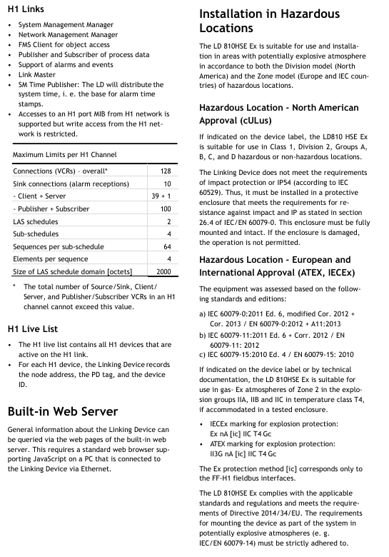
Resource limit (single H1 channel): There are clear restrictions on the resource configuration of each H1 channel, with specific parameters as shown in the table below (note: the total number of VCRs of source/sink, client/server, and publisher/subscriber types in a single H1 channel must not exceed the "total connections" limit):
H1 channel resource type upper limit value
Total number of connections (VCRs) * 128
Number of overnight connections (alarm reception) 10
Number of client server connections: 39+1
Publisher+subscriber connections 100
LAS scheduling table quantity 2
Number of sub scheduling tables 4
The number of sequences in each sub schedule table is 64
The number of elements in each sequence is 4
LAS scheduling table field size (bytes) 2000
(4) H1 Live List
Record key information of all active H1 devices on the H1 chain, including node addresses, PD tags (Process Data Tags), and device IDs, to provide basic data support for device management and troubleshooting.
(5) Built in web server
Support access through a standard web browser (with JavaScript enabled) to query general information of linked devices (such as device status, configuration parameters, etc.), provided that the PC where the browser is located is connected to LD 810HSE Ex via Ethernet.
Installation and certification in hazardous environments
(1) Applicable environmental model
LD 810HSE Ex is suitable for scenarios with potential explosive environments and complies with the hazardous location classification requirements of the North American "Division model" and the European and IEC national "Zone model".
(2) North American Certification (cULus)
Scope of application: If the equipment label has clear identification, it can be used in Class 1, Division 2, A/B/C/D hazardous or non hazardous locations.
Installation requirements: The equipment itself does not meet the requirements of impact resistance and IP54 (according to IEC 60529), and must be installed in a protective enclosure that complies with section 26.4 of IEC/EN 60079-0 (must meet the requirements of impact resistance and IP rating); The casing must be fully installed and undamaged. If the casing is damaged, the equipment is prohibited from operating.
(3) European and international certifications (ATEX, IECEx)
Certification criteria:
IEC 60079-0:2011 6th edition (including 2012 and 2013 revisions)/EN 60079-0:2012 (including A11:2013 revisions)
IEC 60079-11:2011 6th edition (including 2012 revision)/EN 60079-11:2012
IEC 60079-15:2010 4th edition/EN 60079-15:2010
Scope of application: If the equipment label or technical documentation clearly identifies it, it can be used in Zone 2 gas explosive environments with IIA, IIB, IIC explosive groups, T4 temperature levels after being installed in a tested protective enclosure.
Explosion proof label:
IECEx explosion-proof label: Ex nA [ic] IIC T4 Gc
ATEX explosion-proof label: II3G nA [ic] IIC T4 Gc
Note: [ic] Explosion proof method is only applicable to the FF-H1 fieldbus interface.
Compliance requirements: The equipment complies with relevant standards and regulations, and meets the requirements of Directive 2014/34/EU; When installed as part of a system in potentially explosive environments, it is necessary to strictly comply with the requirements of standards such as IEC/EN 60079-14.
At ABB Ability ™ Integration in IT system (800xA system)
(1) System Architecture Role
In a typical 800xA system architecture, FOUNDATION ™ The Fieldbus subsystem is connected to the control system (such as the AC 800M controller) through the HSE subnet, with LD 810HSE Ex serving as the gateway to establish a communication bridge between the field devices on the H1 link and the HSE subnet. The specific architecture is as follows:
Upper level system: including engineering workstation (Control Builder M workstation), operator maintenance workstation, Fieldbus Builder FF client/server network, and connectivity server with OPC server (FF Connectivity Server).
Control layer: The AC 800M controller is connected to the HSE subnet through the communication interface module CI860 (as the HSE host) to achieve control and data exchange of the Fieldbus subsystem.
Fieldbus subsystem: composed of multiple LD 810HSE Ex linked devices and H1 field devices, the linked devices communicate through HSE protocol and manage the H1 links under them, realizing the forwarding of process data and device management.
(2) Key integration capabilities
Data exchange: With the help of HSE data forwarding function, periodic communication between different H1 link on-site devices and HSE subnet devices can be configured to meet real-time control requirements.
Alarm integration: The alarms and events of H1 devices are transmitted to the FF connectivity server through linked devices, seamlessly integrated into the alarm management system of the 800xA system for unified monitoring and processing.
Redundant configuration: Supports LD 810HSE Ex redundant deployment, where the corresponding H1 ports of two physically linked devices in the redundant group are connected to the same H1 link, and redundant control information is exchanged through redundant link wiring to enhance system reliability.
Technical specifications and parameters
Technical parameter category specific parameters
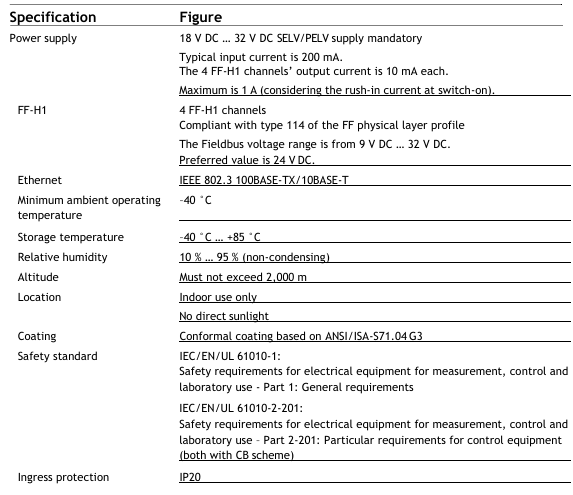
Power supply input voltage: 18 V DC~32 V DC (mandatory requirement for SELV/PELV power supply); Typical input current: 200 mA; 4 FF-H1 channels output current: 10 mA each; maximum input current: 1 A (including startup surge current)
FF-H1 channel quantity: 4; Compliant with FF physical layer protocol specification Class 114; Fieldbus voltage range: 9 V DC~32 V DC (recommended value 24 V DC)
Ethernet complies with the IEEE 802.3 standard; Supports 100BASE-TX (100 Mbit/s) and 10BASE-T (10 Mbit/s)
Environmental temperature: Operating temperature: -40 ° C~+70 ° C; Storage temperature: -40 ° C~+85 ° C
Relative humidity 10%~95% (non condensing)
The highest altitude shall not exceed 2000 meters
Installation location for indoor use only; Avoid direct sunlight
The coating complies with the ANSI/ISA-S71.04 G3 standard and is a three proof coating (moisture-proof, salt spray resistant, and mold resistant)
The safety standards comply with IEC/EN/UL 61010-1 (Safety Requirements for Electrical Equipment for Measurement, Control and Laboratory Use - Part 1: General Requirements) and IEC/EN/UL 61010-2-201 (Part 2-201: Special Requirements for Control Equipment), both of which have passed the CB certification system
Protection level IP20
- YOKOGAWA
- Reliance
- ADVANCED
- SEW
- ProSoft
- WATLOW
- Kongsberg
- FANUC
- VSD
- DCS
- PLC
- man-machine
- Covid-19
- Energy and Gender
- Energy Access
- Renewable Integration
- Energy Subsidies
- Energy and Water
- Net zero emission
- Energy Security
- Critical Minerals
- A-B
- petroleum
- Mine scale
- Sewage treatment
- cement
- architecture
- Industrial information
- New energy
- Automobile market
- electricity
- Construction site
- HIMA
- ABB
- Rockwell
- Schneider Modicon
- Siemens
- xYCOM
- Yaskawa
- Woodward
- BOSCH Rexroth
- MOOG
- General Electric
- American NI
- Rolls-Royce
- CTI
- Honeywell
- EMERSON
- MAN
- GE
- TRICONEX
- Control Wave
- ALSTOM
- AMAT
- STUDER
- KONGSBERG
- MOTOROLA
- DANAHER MOTION
- Bentley
- Galil
- EATON
- MOLEX
- Triconex
- DEIF
- B&W
- ZYGO
- Aerotech
- DANFOSS
- KOLLMORGEN
- Beijer
- Endress+Hauser
- schneider
- Foxboro
- KB
- REXROTH
- YAMAHA
- Johnson
- Westinghouse
- WAGO
- TOSHIBA
- TEKTRONIX
- BENDER
- BMCM
- SMC
- HITACHI
- HIRSCHMANN
- XP POWER
- Baldor
- Meggitt
- SHINKAWA
- Other Brands
- UniOP
- KUKA
- IBA
- Beckhoff
- ADLINK
-
Beckhoff EP9224-0037 - 4-Channel Power Distribution Box EtherCAT
-
Beckhoff CX2900-0026 - Solid State Flash Memory Card 20GB CFast
-
Beckhoff BK7500 - SERCOS Interface Fieldbus Bus Coupler Terminal
-
Beckhoff Ep2328-0002 - 4-Channel Input 4-Channel Output EtherCAT Box IP67
-
Beckhoff CX1020-0111 - Controller Kit Combo Interface Modules
-
B&R X20AI2237 - X20 System Analog Input Interface Module
-
Beckhoff CP2221-0010 - Multi-Touch Built-In Panel PC Touchscreen
-
Beckhoff CX1500-M310 - Fieldbus Master Interface Module 24V
-
Beckhoff CX2100-0904 - Power Charging Module Smart UPS Extension
-
Beckhoff CP3918-0000 - Multi-Touch Control Panel 18.5-Inch Monitor
-
Beckhoff CP2915-0000 - 15-Inch Multi-Touch Built-In Control Panel
-
Beckhoff CP7037-1027 - HMI Industrial Control Panel Built-In PC
-
Beckhoff EL3152 - 2-Channel Analog Input Terminal 4-20mA EtherCAT
-
Beckhoff CP6607-0000-0020 - 5.7-Inch Built-In Panel PC HMI Touch
-
Beckhoff EJ1809-0000 - 16-Channel Digital Input Pluggable Signal Level Terminal
-
Beckhoff AM8563-0N10-0000 - Synchronous Servo Motor
-
Beckhoff AX2006-S60600-520 - Compact Servo Drive Inverter
-
Beckhoff AM8053-0K20-0000 - Servo Motor with Planetary Gearbox AG3210
-
Beckhoff AM8042-0FH1-0000 - Synchronous Servo Motor
-
Rexroth R911338600 - IndraControl V HMI Terminal Beckhoff PCI Card FC9002
-
Beckhoff AX5125-0000 - 3 Phase Industrial Servo Drive 1000Hz
-
Beckhoff EP2328-0002 - 4-Channel Digital Input 4-Channel Output EtherCAT Box
-
B&R 7CP476-02 - System 2005 RTD CPU Module 3IF681.86 Interface
-
Beckhoff AX8620-0000-0000 - Power Supply Module Axis Drive System
-
Beckhoff CX1010-0111 - PLC Module CPU Controller 24V
-
Beckhoff AM8043-0H10-0000 - Synchronous Servo Motor
-
Beckhoff C6240-1009 - Control Cabinet Industrial PC Mainframe
-
Beckhoff BX8000-0000 - Bus Terminal Controller HW 4.4 Standalone
-
Beckhoff CP7721-1089-0020 - 12.1-Inch Touch Screen HMI Panel PC
-
Beckhoff CP7132-0001 - Industrial Built-In Panel PC Screen
-
Beckhoff CP2912-0010 - Multi-Touch Built-In Control Panel Display
-
Beckhoff CP2915-0000 - 15-Inch Multi-Touch Built-In Control Panel
-
Beckhoff AM8532-1EN0-0000 - Synchronous Servo Motor
-
Beckhoff AX5203-0000 - 2-Channel Digital Compact Servo Drive
-
Beckhoff CX2020-0141 - Embedded PC Core CPU Module
-
Beckhoff CP6832-0002-0010 - Built-In Industrial Control Panel Display
-
Beckhoff CX5020-0112 - Embedded PC CPU Control Module
-
Beckhoff CX5140-0175 - 4GB Embedded PC CPU Unit 24V
-
Beckhoff EL3681-0030 - Digital Multimeter Calibration Terminal EtherCAT
-
Beckhoff CP7201-1000-0000 - Industrial PC Touch Screen HMI Monitor
-
Beckhoff CP7232-1001-0000 - Industrial Panel PC Touch Screen
-
Beckhoff C6930-1032-0040 - Control Cabinet Industrial PC System
-
Beckhoff AX5125-0000 - 3 Phase Industrial Servo Drive 1000Hz
-
Beckhoff CP3916-1424-0000 - Multi-Touch Built-In Control Panel
-
B&R 1900071142 - Lemoine Fieldbus Communication Interface Module
-
Beckhoff EL2872 - 16-Channel Ribbon Cable Digital Output Terminal
-
Beckhoff CX2030-0120 - Embedded PC CPU Base Module Controller
-
Beckhoff CP3919-0000 - 19-Inch Multi-Touch Control Panel Touchscreen
-
Beckhoff AX5101-0000-0202 - Servo Driver Compact Intelligent Drive 180V
-
Beckhoff CX5130-0135 - Embedded PC Controller Module
-
Beckhoff CP3719-1061-0010 - Multi-Touch Panel PC Outer Housing Enclosure
-
Beckhoff CP3919-1033-0000 - 19-Inch Touch Industrial Panel Keyboard
-
Beckhoff CX5020-0111 - Embedded PC PLC CPU Module
-
Beckhoff FC5102-0000 - 2-Channel CANopen PCI Control Board Card
-
Beckhoff CX9001-1101 - Embedded PC CPU Network I/O System Module
-
Beckhoff CX1100-0920 - Smart Position Sensor Interface Module
-
B&R 4P3040.01-490 - Operator Panel PLC Interface Communication Module
-
Beckhoff CP2612-0000 - Dual-Touch Built-In Panel PC HMI
-
Beckhoff CP7002-1043-0010 - Touchscreen Display HMI Panel Terminal
-
Beckhoff CX9020-0115 - Embedded PC Controller Module
-
Beckhoff CX5140-0155 - 4GB Embedded PC CPU Module Die Industry
-
B&R 7DI435.7 - System 2005 Universal Digital Input Output Module
-
Bihl+Wiedemann BWU1568 - AS-i Master to Profibus Gateway Module
-
Beckhoff C6920-0070 - Control Cabinet Industrial PC 8GB Win 10
-
B&R X20AI2322 - 2-Channel Temperature Analog Input Module
-
Beckhoff CP2912-0000 - 12-Inch Touchscreen Display Monitor Screen
-
Beckhoff CP6022-1001-0010 - 15-Inch Built-In Control Panel
-
Beckhoff AM8031-0D10-0000 - Synchronous Servo Motor
-
Beckhoff CX5010-0111 - Embedded PC Controller CPU Module
-
Beckhoff CP7232-1000-0000 - Industrial Panel PC Touch Display Screen
-
Beckhoff CP7802-0011-0000 - 15-Inch Industrial Touchscreen Control Panel
-
Beckhoff C6320 - Control Cabinet Industrial PC
-
Beckhoff CX1030-0012 - Basic CPU Module Windows CE 6.0
-
Beckhoff CP2919-0000 - Installation Multi-Touch Control Panel
-
Beckhoff CX1020-0000 - Controller Set Stack System Pack
-
B&R 3DO480.6 - System 2005 Digital Output Module
-
Beckhoff EL3101 - 1-Channel Analog Input Terminal Differential +/-10V
-
Beckhoff AX8108-0200-0000 - Axis Feed Module Servo Drive
-
Beckhoff CP7802-1241-0010 - 15-Inch Industrial Touchscreen Control Panel
-
Beckhoff FC2002-0000 - 2-Channel Lightbus Data Acquisition PCI Card
-
Beckhoff CX5120-0155 - 2GB Embedded PC Intel Atom Controller
-
Beckhoff Cx9020-0111 - 1GB Basic CPU Module Embedded PC
-
Beckhoff CP6901-0001-0000 - 12-Inch Economy Built-In Control Panel
-
Beckhoff CX9020-0111 - Embedded PC CPU Basic Module
-
Beckhoff CX5130-0100 - 4GB Embedded PC CPU Module
-
Beckhoff CP2715-0010 - Multi-Touch Built-In Panel PC
-
Beckhoff CX2033-0175 - Embedded PC CPU Module Core i7
-
Beckhoff CP7201-1000-0000 - 12-Inch Touchscreen Panel PC AMAT Green Box
-
Beckhoff EL4038 - 8-Channel Analog Output Terminal 0-10V EtherCAT
-
Beckhoff CP6802-0000-0000 - Built-In Control Panel HMI Screen
-
Beckhoff CP6500-1012-0060 - Control Cabinet PC Interface Unit
-
Beckhoff FC5202-0000 - 2-Channel DeviceNet Master PCI Interface Card
-
Beckhoff CP6606-0001-0020 - 7-Inch Economy Panel PC Touch
-
Beckhoff CP2921-0010 - Multi-Touch Integrated Control Panel Display
-
Beckhoff CP7802-0001-0010 - 15-Inch Touch Screen Control Panel HMI
-
Beckhoff C6920-0050 - Control Cabinet Industrial PC
-
Beckhoff BK9105 - EtherNet/IP Bus Coupler Network Interface
-
Beckhoff 31 Modules - Bus Terminal Slice I/O Lot Assortment
-
Beckhoff CX2020-0120 - Embedded PC Basic CPU Module 8GB CFast Card
-
Beckhoff CP7001-0000 - HMI Control Panel Touch Screen
-
B&R 7EX484.50-1 - System 2005 Controller Base Module Slots
-
Beckhoff EK1322 - 2-Port EtherCAT P Extension Feed-In Terminal
-
Beckhoff CP6606-0001-0020 - 7-Inch Single-Touch Economy Panel PC
-
Beckhoff CP6607-0001-0000 - Economy Installation Operator Panel PC 5.7-Inch
-
Beckhoff AX5103-0000-0200 - Digital Compact Servo Driver 3 Phase
-
Beckhoff CP7802-0001-0010 - 15-Inch Touch Screen Control Panel
-
Beckhoff AX8620 - Power Supply Module Axis System
-
Beckhoff CX2030-0121 - Embedded PC Controller Module
-
Beckhoff CP6606-0001-0020 - 7-Inch Economy Panel PC Touch Screen
-
Beckhoff CX2030-0121 - Embedded PC CPU Module Windows Standard 7
-
Beckhoff BX3100-0000 - PROFIBUS DP Bus Terminal Controller
-
Beckhoff CX1020-0000 - Controller Set with Power Supply Unit
-
Beckhoff EK1100 - EtherCAT Coupler Terminal Module Set
-
Beckhoff CP7002-1043-0010 - HMI Display Panel with Control Panel Bracket
-
Beckhoff AM8031-0D10-0000 - Synchronous Servo Motor
-
Beckhoff CX5130-0175 - Embedded PC 4GB RAM Controller
-
Beckhoff CX5130-0155 - Embedded PC Automation Controller
-
Beckhoff C6930-0010 - Control Cabinet Industrial PC Core Duo
-
Beckhoff CP3924-0000 - Multi-Touch Control Panel Display
-
Beckhoff AM8023-0F20-0000 - Synchronous Servo Motor
-
B&R KL3362 - Bus Terminal Thermocouple Input Module
-
Beckhoff AL2006-0000-0000 - Linear Servo Motor Three Phase
-
Beckhoff CX5140-0155 - Embedded PC CPU Controller Module
-
Beckhoff FC9002 - Ethernet PCI Network Interface Card
-
Beckhoff CP7203-0021-0040 - Built-In Panel PC 19-Inch Touch Screen
-
Beckhoff C6930-0020 - Control Cabinet Industrial PC HDD CF Card
-
Beckhoff CX2900-0033 - Memory Card CFast Storage
-
Beckhoff CP6201-0001-0020 - Built-In Panel PC Display

K-JIANG

Add: Jimei North Road, Jimei District, Xiamen, Fujian, China
Tell:+86-15305925923