
K-WANG


Barber Colman MA41-7153-502 and similar series actuators
Key feature: Mechanical spring reset (clockwise/counterclockwise optional), ensuring reliable reset after power loss; 95 ° rotation stroke (can be limited by accessories to 30 ° -95 °); Visual position indicator; Overload protection during full rotation process; Some models come with built-in auxiliary switches for signal interaction or interlock control.
Barber Colman MA41-7153-502 and similar series actuators
Product core positioning and series differences
1. Core functions and applications
Purpose: Used for the "on-off" control and fail safe (power-off spring reset) operation of air doors and valves in HVAC systems, supporting direct coupling installation, and some models can be connected in parallel (linkage installation) to meet high torque requirements.
Key feature: Mechanical spring reset (clockwise/counterclockwise optional), ensuring reliable reset after power loss; 95 ° rotation stroke (can be limited by accessories to 30 ° -95 °); Visual position indicator; Overload protection during full rotation process; Some models come with built-in auxiliary switches for signal interaction or interlock control.
2. Differences in Series Models
The three major series are distinguished by torque level, voltage specifications, and additional functions, with the following core differences:
Series torque levels (lb in/N-m) voltage specifications core features auxiliary switch configuration manual override function
MA40-704X 35 (4) 24Vac/DC, 120Vac, 230Vac NEMA 2/IP54 protection (no installation restrictions), travel limiter standard with some models (-501) including 1 SPDT switch (0-95 ° adjustable) none
MA4X-707X 60 (7) 24Vac/DC, 120Vac, 230Vac NEMA 2/IP54 protection (requires downward installation of conduit), supports rotation restriction part models (-502) including 2 SPDT switches (1 fixed at 5 °, 1 adjustable at 25-85 °) MA41-707X series has (-5 ° to 85 ° adjustable)
MA4X-715X 133 (15) 24Vac/DC, 120Vac, 230Vac, same as MA4X-707X, with maximum torque, can be installed in parallel with two machines. Some models (-502) include two SPDT switches (one fixed at 5 ° and one adjustable at 25-85 °). The MA41-715X series has (-5 ° to 85 ° adjustable)
MA41-7153-502 Exclusive Attributes: Belonging to the MA4X-715X series, powered by 24Vac/DC, 133lb in (15N-m) torque, including 2 SPDT auxiliary switches, with manual override function, supporting dual machine parallel connection.
Key technical parameters
1. Electrical parameters
Specific specifications for parameter categories (taking MA41-7153-502 as an example, refer to Table 1 for other models)
Supply voltage 24Vac ± 20% or 22-30Vdc
Power consumption operation: 9.8VA (50Hz), 9.7VA (60Hz); Maintain: 7.5VA (50/60Hz)
Current running DC current 0.29A; locked rotor current 2.8A
2 SPDT auxiliary switches, resistive load 7A at 250Vac, inductive load 2.5A
Control signal single pole single throw (SPST) control contact or bidirectional thyristor (500mA rated)
Wiring 3-foot (91cm) equipment cable, 1/2-inch conduit interface (equipped with AM-756 convertible M20 metric conduit)
2. Mechanical and environmental parameters
Rotation stroke: Maximum 95 °± 5 °, MA40-704X series comes standard with a travel limiter, MA4X-707X/715X requires AM-689 accessories to achieve 30 ° -95 ° adjustment.
Wind door shaft adaptation:
MA40-704X: Standard fixture supports ≤ 5/8 inch (15mm) circular axis or ≤ 1/2 inch (13mm) square axis; AM-710 accessories support ≤ 3/4 inch (19mm) circular shafts.
MA4X-707X/715X: Standard fixture supports ≤ 3/4 inch (19mm) circular axis or ≤ 1/2 inch (13mm) square axis; AM-687 accessories support circular shafts ≤ 1.05 inches (27mm) or square shafts ≤ 5/8 inches (15mm).
Protection level: MA40-704X is NEMA 2/IP54; MA4X-707X/715X is NEMA 1/IP30 (NEMA 2/IP54 when the conduit is facing downwards).
Environmental conditions: Operating temperature -22 ° F to 140 ° F (-30 ° C to 60 ° C); Storage/transportation temperature -40 ° F to 160 ° F (-40 ° C to 71 ° C); Humidity 15% -95% RH (non condensing).
Certification: UL 873, CUL (Canada), CE (compliant with EMC/Low Voltage Directive), C-Tick Australia.
Installation specifications and operating procedures
1. Preparation before installation
Personnel requirements: It must be operated by qualified professional technicians who are familiar with national/local electrical regulations.
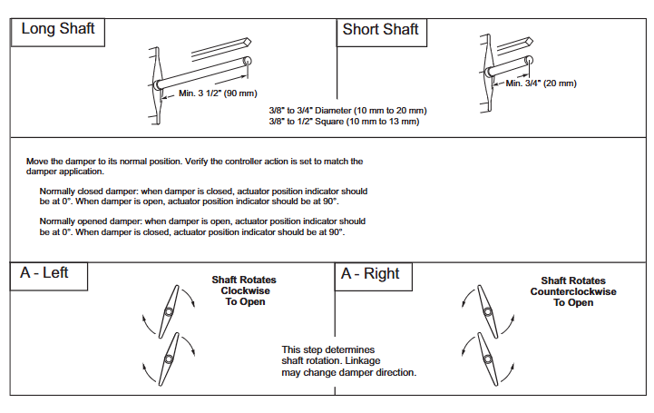
Tools and accessories: Please bring your own # 8 sheet metal screws, 10mm wrench, 7/16 inch wrench, 1/8 inch hex wrench, and screwdriver; Select the corresponding fixture based on the shaft diameter (such as AM-710, AM-687), and the installation method for the long axis (≥ 3.5 inches/90mm) and short axis (<3.5 inches/90mm) is different.
Safety warning: Disconnect the power supply before installation to prevent electric shock; Avoid approaching strong electromagnetic interference sources such as contactors and large motors; It is prohibited to drill holes in the actuator body (there are 6 pre drilled holes under the labels on both sides for accessory installation).
2. Core installation steps (divided into series)
(1) MA40-704X series
Wind door positioning: Adjust the wind door to the normal position (the indicator indicates 0 ° when the normally closed wind door is closed, and 0 ° when the normally open wind door is open), and confirm the direction of shaft rotation (clockwise/counterclockwise opening).
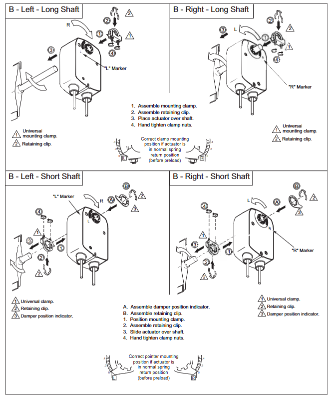
Fixture installation: For short shafts (<3.5 inches), the air door position indicator should be installed first, then the actuator should be inserted and the fixture nut should be manually tightened; Insert the long axis directly into the actuator and manually pre tighten the fixture.
Fixing and Calibration: After aligning the centerline, drill a hole to fix the bracket, loosen the clamp nut, rotate the actuator 5 ° in the direction of operation (without moving the shaft), then tighten the clamp nut with a torque of 4-6lb ft (5.4-8.2N-m), and finally fix the bracket screw.
(2) MA4X-707X/715X series (including MA41-7153-502)
The basic steps are the same as MA40-704X, but please note:
The conduit interface needs to be installed facing downwards to meet IP54 protection requirements;
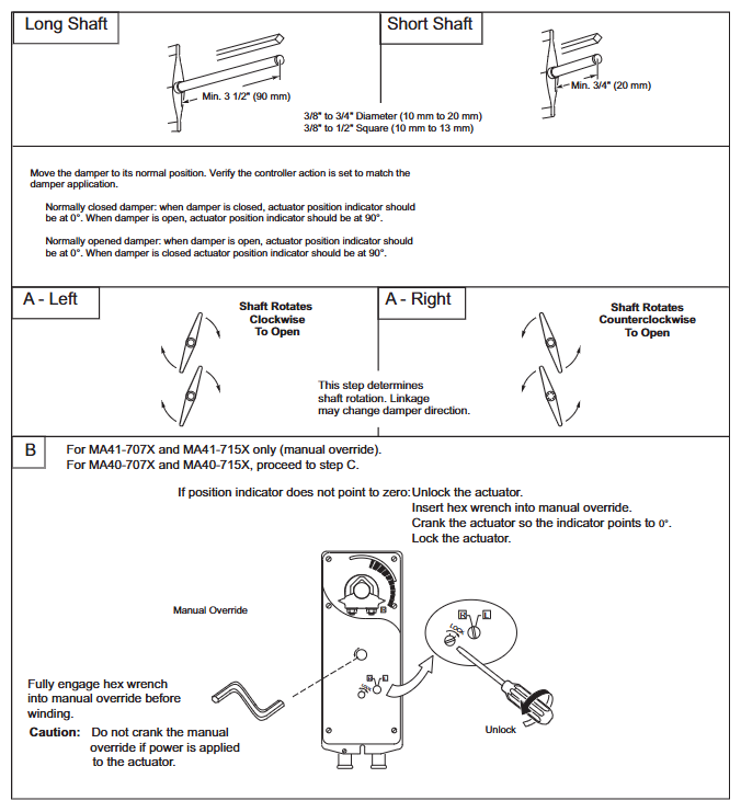
MA41-707X/715X series with manual override: In the power-off state, use an Allen wrench to adjust the indicator to 0 ° and lock it. After installation, it will automatically unlock when powered on for the first time;
The tightening torque of the fixture is 8-10 lb ft (11-14 N-m), which is higher than the MA40-704X series.
3. Special installation scenarios
Dual machine parallel connection (linkage installation): AM-673 bracket is required, and all actuator L2 wires are connected to the transformer common terminal and L1 wires are connected to the live wire, ensuring consistent polarity and total current not exceeding the rated value of the transformer and control circuit.
Long axis/short axis adaptation: For shaft lengths ≥ 3.5 inches (90mm), use the long axis installation method; When using the short axis method for spaces smaller than 3.5 inches or when the space is narrow, an additional position indicator needs to be adapted.
Wiring and Debugging
1. Wiring specifications
Voltage corresponds to line color: 24Vac/DC model (such as MA41-7153-502) L1=red, L2=black; 120Vac model L1=black, L2=white; 230Vac model L1=brown, L2=light blue (see Table 2 and Table 5 for details).
Auxiliary switch wiring: The two switches of MA4X-715X-502/MA4X-707X-502 are respectively "5 ° fixed" (purple/yellow/orange line) and "25-85 ° adjustable" (purple white/yellow white/orange white line), used for indicating the position of the air door end and interlocking the fan start.
Wiring requirements: Class 2 control/power lines should be wired separately from line voltage lines and non-Class 2 circuits; The auxiliary switch line needs to be connected to a Class 1 circuit.
2. Debugging and Inspection
Power on test: After power on, the actuator should drive the air door to the "power on position", and after power off, the spring should be reset to the "normal position". Repeat the test 3 times to confirm reliability.
Auxiliary switch verification: For models with suffix -501/-502, manually adjust the switch pointer to the target angle and power on to verify whether the on/off status of the switch meets the requirements.
Rotation limit verification: If installing AM-689 (MA4X series) or using the built-in stroke limiter of MA40 series, it is necessary to test whether the rotation angle of the air door meets the design value (such as 45 °, 60 °) by powering on.
Operations and troubleshooting
1. Maintenance requirements
Daily maintenance: The actuator is designed to be maintenance free and does not require regular maintenance under normal use (in compliance with environmental and installation requirements). It only needs to be checked regularly by an electrician according to EN standards for the overall system status.
Manual override use: Only available in the MA41-707X/715X series. To operate when power is off, insert an Allen wrench into the override hole and rotate it to the target angle (-5 ° to 85 °). It is strictly prohibited to use it when powered on or in parallel with two machines (to avoid gear damage).
2. Troubleshooting
Possible causes and solutions for the fault phenomenon
Not functioning after power on: 1. The power supply is not properly connected or the voltage does not match; 2. The control contacts are not closed; 3. The fixture is too tight and stuck. 1. Check the wiring and voltage (e.g. 20-28Vac is required for 24Vac); 2. Confirm the continuity of SPST contacts; 3. Loosen the clamp nut and recalibrate the torque
1. Failure to reset due to power loss. Spring damage; 2. The air door is stuck; 3. The position of the rotation limiter is incorrect. 1. Replace the actuator; 2. Check the mechanical resistance of the air door; 3. Adjust the position of the limiter again
Auxiliary switch has no signal. 1. Wiring error; 2. The switch pointer is not aligned with the target angle; 3. The switch is damaged. 1. Check the wire color and wiring diagram; 2. Adjust the pointer again after power failure; 3. Replace the actuator
3. Disposal and Warranty
Scrap disposal: Metal, plastic, and electronic components must be disposed of in accordance with local regulations and can be returned to Barber Colman (shipping costs borne by the sender).
Warranty policy: The entire series is covered by a 5-year warranty, and damages caused by human factors (such as drilling or manual override during power on) are not covered by the warranty.
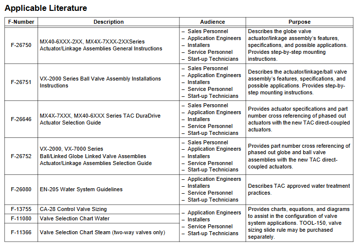
Key accessories and document references
1. Common accessories (adapted by series)
Adaptation series accessories, models, and purposes
MA40-704X AM-710 universal fixture compatible with ≤ 3/4 inch (19mm) circular shaft
MA40-704X AM-709 position indicator combined with travel limiter
MA4X-707X/715X AM-687 is compatible with fixtures for circular shafts ≤ 1.05 inches (27mm) or square shafts ≤ 5/8 inches (15mm)
MA4X-707X/715X AM-689 rotation limiter (adjust travel from 30 ° to 95 °)
Full series AM-673 dual machine parallel (linkage installation) bracket
Full series AM-756 M20 metric conduit to 1/2 inch NPT interface adapter
- YOKOGAWA
- Reliance
- ADVANCED
- SEW
- ProSoft
- WATLOW
- Kongsberg
- FANUC
- VSD
- DCS
- PLC
- man-machine
- Covid-19
- Energy and Gender
- Energy Access
- Renewable Integration
- Energy Subsidies
- Energy and Water
- Net zero emission
- Energy Security
- Critical Minerals
- A-B
- petroleum
- Mine scale
- Sewage treatment
- cement
- architecture
- Industrial information
- New energy
- Automobile market
- electricity
- Construction site
- HIMA
- ABB
- Rockwell
- Schneider Modicon
- Siemens
- xYCOM
- Yaskawa
- Woodward
- BOSCH Rexroth
- MOOG
- General Electric
- American NI
- Rolls-Royce
- CTI
- Honeywell
- EMERSON
- MAN
- GE
- TRICONEX
- Control Wave
- ALSTOM
- AMAT
- STUDER
- KONGSBERG
- MOTOROLA
- DANAHER MOTION
- Bentley
- Galil
- EATON
- MOLEX
- Triconex
- DEIF
- B&W
- ZYGO
- Aerotech
- DANFOSS
- KOLLMORGEN
- Beijer
- Endress+Hauser
- schneider
- Foxboro
- KB
- REXROTH
- YAMAHA
- Johnson
- Westinghouse
- WAGO
- TOSHIBA
- TEKTRONIX
- BENDER
- BMCM
- SMC
- HITACHI
- HIRSCHMANN
- XP POWER
- Baldor
- Meggitt
- SHINKAWA
- Other Brands
- UniOP
- KUKA
- IBA
- Beckhoff
-
ADLINK PCI-7433 - switch value acquisition card Isolated Digital Input Card
-
ADLINK PCI-9112 - 51-12252-0D20 Multi-Function Data Acquisition Card
-
ADLINK NUPRO-A301 REV:1.4 - industrial control motherboard PICMG Full-Size SBC
-
ADLINK 51-18502-0A10 - Frame Grabber Image Acquisition Interface Card
-
ADLINK PCI-7296 - 51-12009-0A50 PCB-I-E-925=6DX1 96-CH Parallel Digital I/O Board
-
ADLINK PCI-8132 GP A2 - Motion Control Card 2-Axis Servo & Stepper Controller
-
ADLINK PCI-7442 - switch quantity card data acquisition card 64-CH Isolated Card
-
ADLINK HPX-13S4 - baseboard PICMG 1.3 Passive Backplane Chassis Baseplate
-
ADLINK NuPRO-590 / NTC-567-ZM-F36 - Single Board Computer PCB-I-E-1853=9L21 Half-Size SBC
-
ADLINK PCIe-8332 - 16-axis plate Motion Control Hardware Card
-
ADLINK NuPRO-775 REV.B1 - motherboard Pentium 4 Full-Size PICMG SBC
-
ADLINK PXI-3920 - Embedded Controller 3U PXI cPCI System Intelligence Board
-
ADLINK PCI-8134 - driver card motion control card 4-Axis Controller Board
-
ADLINK HSL-DI32-M-N-011 / HSL-TB32-M-DIN - Digital Input & Base Module PLC Distributed I/O System
-
ADLINK PCI-6216V-206 / PCI-208V 009 - 16 CH 16bit analog output card
-
ADLINK NuPro-E330 - 51-41805-0A20 PCB Single Board Computer Host Board
-
ADLINK PCI-1622C - Card 8-Port RS-232/422/485 PCI Serial Communication Board
-
ADLINK PCIe-7432 - 51-18402-0A10 Carte PCIe Avec Plage D'Entrée Élevée Isolated DIO Card
-
ADLINK PCI-7250 - PCI Acquisition Card 8-CH Relay Output Isolated DI Card
-
ADLINK PCI-7230 - 32-CH Isolated Digital I/O Card
-
ADLINK PCI-8164 - PCB 4-Axis Motion Controller Card
-
ADLINK PCI-7854 - Collection card High-Speed Link Distributed Motion Controller
-
ADLINK NuPRO-935A/LV - industrial control computer motherboard Full-Size PICMG SBC
-
ADLINK IMB-M40H - motherboard IH61-AA4 1155 LGA1155 Micro-ATX Mainboard
-
ADLINK PCI-7248 - Linhua 51-12006-0A40 48-CH Parallel Digital I/O Card
-
ADLINK HPCI-14S12U - Linhua industrial computer baseboard Passive Backplane
-
ADLINK PCI-8132 Rev.A2 - 2-Axis Servo & Stepper Motion Controller Card
-
ADLINK ACL-8111 - ISA card Multi-Function DAQ Card
-
ADLINK ACL-8111 - ISA card Multi-Function Data Acquisition Board
-
ADLINK PCI-7200 REV.A3 - Digital I/O card 12MB/s High-Speed Parallel Digital I/O
-
ADLINK PCI-7296 REV.A3 - 96-CH High-Density Opto-Isolated DIO Card
-
ADLINK PCI-7434 - 64-CH Isolated Digital Output Card
-
ADLINK M-342 - atx motherboard Industrial PC Mainboard
-
ADLINK NuPRO-935ADV (A) 1.9 - CPU Board Intel Core 2 Quad CPU Q9500 2.83GHz PICMG Board
-
ADLINK NUPRO-935A/DV - motherboard dual network port 51-41802-0A10 CPU Board
-
ADLINK PCI-RTV24 - image capture card Analog Video Frame Grabber Board
-
ADLINK HPX-13S4 - device baseboard PICMG 1.3 Passive Backplane Chassis Baseplate
-
ADLINK PCI-8134A - control card 4-Axis Motion Controller Card
-
ADLINK ACL-7130 REV. B2 - industrial control capture card Isolated Digital I/O Board
-
ADLINK EBP-13E2 - Industrial Backplane Board Passive Backplane Baseboard
-
ADLINK NuPRO-935ADV (A) 1.9 - CPU Board Intel Core 2 Quad CPU Q9500 2.83GHz PICMG SBC
-
ADLINK PCI-8134A - motion control card 4-Axis Pulse-Train Controller Card
-
ADLINK PCI-9112 REV A.1 - Multi Function DA&C Board Data Acquisition Card
-
ADLINK 51-12001-0C20 - Circuit Board Multi-Function Data Acquisition Hardware
-
ADLINK PCI-7300A - 80-CH High-Speed Digital I/O Card
-
ADLINK PCI-7230 - 16-CH Isolated Digital Input Output Card
-
ADLINK DIN-814-GP - motion control module Interface Terminal Block
-
ADLINK NUPRO-A40H - 51-41807-1A20 Industrial Control Motherboard LGA1155
-
ADLINK PCI-7433 rev A2 - Isolated Digital Input Card
-
ADLINK NuPRO-780 - Pentium III 800 512 MB SBC NuPRO780 51-41309-0B2 Single Board Computer
-
ADLINK PCI-7853 / PCI-7854 - Acquisition card High-Speed Link Control Card
-
ADLINK NUPRO-852 / NUPRO-852LV - Industrial motherboard Full-Size PICMG CPU Board
-
ADLINK NuPRO-842LV/P - 51-41360-0B30 Industrial Motherboard Half-Size PICMG SBC
-
ADLINK PCI-FIW64 - 4/2 Channel IEEE1394B Image Capture Card Frame Grabber
-
ADLINK PCI-7851 Rev A1.1 - HSL system card High-Speed Link Master Controller
-
ADLINK PCI-7230 - 51-12003-0A50 card 32-CH Isolated Digital I/O Card
-
ADLINK NuPRO-841REV:1.0 - Industrial CPU Board Mainboard
-
ADLINK NuPRO-841 REV:1.0 - motherboard Industrial Control PC Mainboard
-
ADLINK PCI-8256 - 8-Axis Advanced Motion Control PCI Board
-
ADLINK PCI-6S / PCI6S - Backplane 6-Slot Passive Backplane Board
-
ADLINK PCI-7234 REV B3 - 32-CH Isolated Digital Output PCI Card
-
ADLINK PCI-8213 - HannStar MV-4 51-45003-0b4 Board
-
ADLINK PCI-7233 - 51-12004-0a20 board PCI7233 32-CH Isolated Digital Input Card
-
ADLINK PCI-7851 - 006 51-24003-0B20 High-Speed Link Master Motion Control Card
-
ADLINK PCI-7432 - 64-CH Isolated Digital I/O PCI Cards
-
ADLINK LPCI-3488 - Card Low Profile IEEE-488 GPIB Interface Card
-
ADLINK HPCI14S REV.B1 - industrial control computer base plate Passive Backplane
-
ADLINK NEON-1020 - Industrial camera Smart Camera Vision System
-
ADLINK PCI-7432 - Isolated Digital I/O PCI Card 64-CH
-
ADLINK Pcm-7250+ - 8-Ch Relay Outputs & 8-Ch Isolated DI Module PC/104
-
ADLINK CPCI-7841 - DUAL-PORT ISOLATED CAN INTERFACE CARD CompactPCI
-
ADLINK PCI-3488 / PCI-GPIB - PCI IEEE-488 GPIB Interface Card
-
ADLINK PCI-1711U - Card Multi-Function Data Acquisition Board
-
ADLINK NUPRO-A301 - REV:1.1 1.2 1.4 PICMG Full-Size Single Board Computer
-
Adlink DIN-50S-01 - PLOTECH 51-14024-0A40 50-pin Wiring Terminal Board
-
Chroma 52962 / 58183 - PXI Optical Spectrometer carrier adapter Card
-
ADLINK PCI-6208V - PCI DATA ACQUISITION & RECORDING CARD 8-CH Analog Output
-
ADLINK HSL-DI32-DB-N - Industrial Control Board Distributed Digital Input Module
-
ADLINK HSL-AO4-U - 4-CH HIGH SPEED LINK ANALOG OUTPUT MODULE Distributed I/O
-
ADLINK PCI-7396 - 0050 GP 51-12012-0B20 96-CH High-Speed Digital I/O Card
-
ADLINK NUPRO-935A/DV - 51-41802-0A10 motherboard Industrial CPU Single Board Computer
-
ADLINK PCI-9111 DG - Industrial Acquisition Card Multi-Function DAQ Card
-
ADLINK NuPRO-E315 - industrial computer motherboard Intel Atom SHB SBC
-
ADLINK NUPRO-406 REV:B1 - Industrial Control Motherboard Full-Size PICMG CPU Board
-
ADLINK NuPRO-E330 - motherboard Industrial Control System Host Board PICMG 1.3
-
ADLINK ACL-6128A 103 - 51-11002-1A4 2-CH Isolated Analog Output Card
-
XTRAMUS cPS-H325/AC - POWER SUPPLY NUSTREAMS 600 NETWORK TESTING EQUIPMENT Power Module
-
ADLINK DIN-814P-A4 - 51-14056-0A10 Terminal Block Motion Control Breakout Board
-
ADLINK TB-24P/24-01 - 24-Channel Card Terminal Breakout Board
-
ADLINK PCI-7251 - 51-12008-0A30 PCI7251 8-CH Relay Output Isolated Digital Input Card
-
ADLINK HSL-TB64-DIN REV A1 / HSL-DO32-DB-N - 2ea Board Breakout Terminal Board Distributed I/O Module
-
ADLINK NuPRO-865 REV 3.0 - industrial computer motherboard Full-Size PICMG SBC
-
ADLINK NUPRO-A40H - motherboard 51-41807-1A30 OSP H61 Industrial PC Mainboard
-
ADLINK LPCI-3488A - PCI Card 51-12801-0A30 GPIB Interface Card
-
ADLINK DIN-825-4P0 - 51-14085-0A30 Terminal Printed Circuit Board Breakout Block
-
ADLINK IMB-T10/D2550 V - MOTHER BOARD 80-PXG160-A1A01 IMB-T10-M2G-S32G Industrial Mainboard
-
ADLINK PCI-8144N - Motion Control card Stepper Motor Controller
-
ADLINK PCI-7433 - Digital acquisition card Isolated Digital Input Card
-
ADLINK PCI-9112 DG - Data Acquisition card 51-12252-0D20 Multi-Function DAQ
-
ADLINK IMB-M40H - motherboard IH61-AA4 1155 LGA1155 Micro-ATX Mainboard
-
ADLINK TB-24P/24-01 - Carte 24 voies Terminal Breakout Board Connector Module
-
ADLINK HSL-D16DO16-M-NN - Distributed Discrete Input Output I/O Module
-
ADLINK PCI-7248 - PCI CARD 51-12006-0A40 48-CH Parallel Digital I/O Board
-
ADLINK HSL-DI32-DB-N - Industrial Control Board Distributed I/O Digital Input Module
-
ADLINK PCI-7433 - Pci 7433 Isolated Digital Input Card
-
ADLINK PCI-6208V - 008 Data acquisition card 8-CH Analog Output Card
-
ADLINK IH61-AA4 - industrial motherboard LGA1155 Micro-ATX Mainboard
-
ADLINK PXI-3920 - PXI 3U cPCI Industrial Controller Embedded System CPU Board
-
ADLINK PCI-6308 - Analog Output DAQ Card Isolated Voltage Output Card
-
ADLINK PCI-7200 - data acquisition card REV.A3 High-Speed Parallel DIO Card
-
ADLINK NuPRO-E315 - Industrial Control Computer Motherboard PICMG 1.3 SHB SBC
-
ADLINK PCI-1610C - Card 4-Port Isolated RS-232 PCI Serial Communication Card
-
ADLINK PCI-1716 - Card High-Resolution Multi-Function DAQ Card
-
ADLINK MI-965 - Industrial Mini-ITX Motherboard CPU Board
-
ADLINK PCI-1610A - Card 4-Port RS-232 PCI Serial Communication Card
-
ADLINK cBP-3208/3208R - CPCI Board 3U 8-Slot CompactPCI Backplane
-
ADLINK PCI-8134A - 51-12421-0A10 4-Axis Motion Controller Card
-
ADLINK PCI-8164 - Motion Control Card 4-Axis Advanced Controller Card
-
ADLINK NUPRO-935A/DV - motherboard dual network port 51-41802-0A10 CPU Board
-
ADLINK PCI-7248 - 51-12006-0A40 acquisition card 48-CH Parallel DIO Card
-
ADLINK PCI-7443 - 51-12022-0A10 BOARD 128-CH Isolated Digital Input Card
-
ADLINK DIN-825-GP4 - Terminal Block Interface Board Breakout Module
-
ADLINK PCI-7248 - Card 48-CH Parallel Digital I/O Card
-
ADLINK NUPRO-865 REV :3.0 - industrial motherboard Intel Pentium 4 CPU Board
-
ADLINK PCI-9113A - Isolated Analog Input Data Acquisition Card
-
ADLINK HPCI-8S4 - REV.B2 Industrial Control Base Plate Passive Backplane
-
ADLINK M-342 - atx motherboard Industrial PC Mainboard
-
ADLINK PCI-RTV24 - image capture card Analog Video Frame Grabber Board

K-JIANG

Add: Jimei North Road, Jimei District, Xiamen, Fujian, China
Tell:+86-15305925923