
K-WANG


TEKTRONIX 3 Series Mixed Domain Oscilloscope MDO32 and MDO34
TEKTRONIX 3 series mixed domain oscilloscopes MDO32 and MDO34
Overview and Scope of Application
The specification and performance verification manual for the Tektronix 3 series hybrid domain oscilloscope (with 2 channels for MDO32 and 4 channels for MDO34) covers three major modules: hardware parameters (analog bandwidth of 100MHz-1GHz, maximum sampling rate of 5GS/s, and 16 optional digital channels), multi domain functionality (oscilloscope+spectrum analyzer+arbitrary function generator+digital voltmeter), and performance verification process (20+tests including input impedance, DC balance, analog bandwidth, etc.). The key indicator range is clearly defined (such as maximum input voltage of 300VRMS, display average noise level ≤ -109dBm/Hz), and standardized testing steps are provided (including required equipment list, wiring diagram, data recording table), while emphasizing safety specifications (CAT II). Provide complete technical guidance for instrument calibration, troubleshooting, and compliance verification, including installation category and grounding requirements.
Model differences and core parameters
Model Features MDO32 (2 channels) MDO34 (4 channels) Remarks
Analog bandwidth 100MHz-1GHz 100MHz-1GHz model sampling rate 5GS/s, other 2.5GS/s
Digital channel 16 channels (3-MSO option) 16 channels (3-MSO option) input capacitor 8pF, minimum signal swing 500mVpp
Spectrum analysis 9kHz-1GHz (standard)/3GHz (3-SA3 option) 9kHz-1GHz (standard)/3GHz (3-SA3 option) Display average noise level ≤ -109dBm/Hz
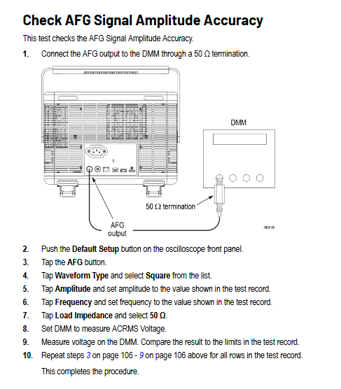
AFG function 1 channel (3-AFG option) 1 channel (3-AFG option) Output waveform includes 13 types such as sine wave, square wave, pulse, etc
Size and weight 370 × 252 × 148.6mm, 5.26kg (1GHz) 370 × 252 × 148.6mm, 5.31kg (1GHz) requires 50.8mm heat dissipation space on the right and rear
Detailed explanation of core hardware specifications
1. Key parameters of simulation channel
Parameter Category Specification Range Remarks
Under the bandwidth of 100MHz/200MHz/350MHz/500MHz/1GHz 1mV/div, the bandwidth of the 1GHz model has been reduced to 150MHz
Sampling rate of 1-5GS/s, maximum 5GS/s when 1-2 channels are activated, and maximum 2.5GS/s when 3-4 channels are activated
Input impedance 1M Ω (± 1%) or 50 Ω (± 1%) 1M Ω input capacitor 13pF ± 2pF
Maximum input voltage 1M Ω: 300VRMS (CAT II); 50 Ω: 5VRMS (peak ≤± 20V) 1M Ω drops to 5VRMS above 450MHz
DC gain accuracy ± 1.5% (5mV/div and above), ± 2.0% (2mV/div), ± 2.5% (1mV/div), with an additional decrease of 0.1% per ℃ above 30 ℃
2. Digital channel (3-MSO option) parameters
Parameter specifications
Number of channels 16 (D0-D15)
Input resistance 101k Ω (typical value)
Input capacitance 8pF (typical value)
Threshold range -15V~+25V
Threshold accuracy ± [130mV+3% x threshold setting] (SPC needs to be performed)
Minimum detectable pulse 2.0ns (requires P6316 probe)
Skew 500ps between channels (typical value)
3. Parameters of spectrum analyzer
Parameter specifications
Frequency range 9kHz-1GHz (standard); 9kHz-3GHz (3-SA3 option)
Resolution bandwidth (RBW) 20Hz-150MHz (1-2-3-5 sequence adjustment)
Display average noise level (DANL) 9kHz-50kHz: ≤ -109dBm/Hz; 5MHz-2GHz:≤-136dBm/Hz
Stray response second harmonic ≤ -55dBc; 3rd harmonic ≤ -53dBc
Phase noise (1GHz CW) 10kHz offset: ≤ -81dBc/Hz; 1MHz offset: ≤ -118dBc/Hz
4. Parameters of any function generator (3-AFG option)
Parameter specifications
13 types of output waveforms including sine wave, square wave, pulse, and ramp
Frequency range: sine wave 0.1Hz-50MHz; Square wave 0.1Hz-25MHz
Range of amplitude 50 Ω load: 10mVpp-2.5Vpp; High resistance load: 20mVpp-5Vpp
DC offset ± 1.25V (50 Ω); ± 2.5V (high resistance)
Rise/fall time 5ns (10% -90%, square wave)
Distortion sine wave ≤ 1% (50 Ω, 1kHz)
Performance verification process
1. Verify the prerequisites
The instrument needs to be preheated in an environment of 18 ℃ -28 ℃ for at least 10 minutes;
Perform signal path compensation (SPC) (path: Utility → Calibration → Run SPC), if the temperature change exceeds 5 ℃, it needs to be re executed;
The oscilloscope and testing equipment need to be connected to the same AC power circuit (to avoid errors caused by ground offset).
2. Core test items and steps (example)
Qualification criteria for key steps of testing equipment in testing projects
Input impedance (1M Ω/50 Ω) DC voltage source, impedance measuring instrument 1. Connect the voltage source to channel 1; 2. Set the vertical gear to 10mV/div/100mV/div; 3. Measure impedance values of 1M Ω: 990k Ω -1.01M Ω; 50 Ω: 49.5 Ω -50.5 Ω
DC balanced 50 Ω terminal load 1. Channel connected to 50 Ω terminal; 2. Set the vertical gear to 1mV/div-1V/div; 3. Convert the measurement mean to divisions 1mV/div (50 Ω): ± 0.5div; 2mV/div and above: ± 0.2div
Analog bandwidth sine wave generator 1. Input 10MHz signal (8div amplitude); 2. Adjust to the maximum bandwidth frequency; 3. Calculate the gain (Vbw pp/Vin pp) with a gain ≥ 0.707 (-3dB point)
Random noise free (internal noise) 1. Disconnect all inputs; 2. Set up a 50 Ω terminal with full bandwidth; 3. Measure AC RMS noise at 100mV/div level: 1GHz model ≤ 3.1mV; 100MHz model ≤ 2.85mV
Digital threshold accuracy DC voltage source, P6316 probe 1. Connect the probe to the voltage source; 2. Set a threshold of 0V/4V; 3. Record Vs - (high → low) and Vs+(low → high) 0V: ± 0.1V; 4V: 3.78V-4.22V
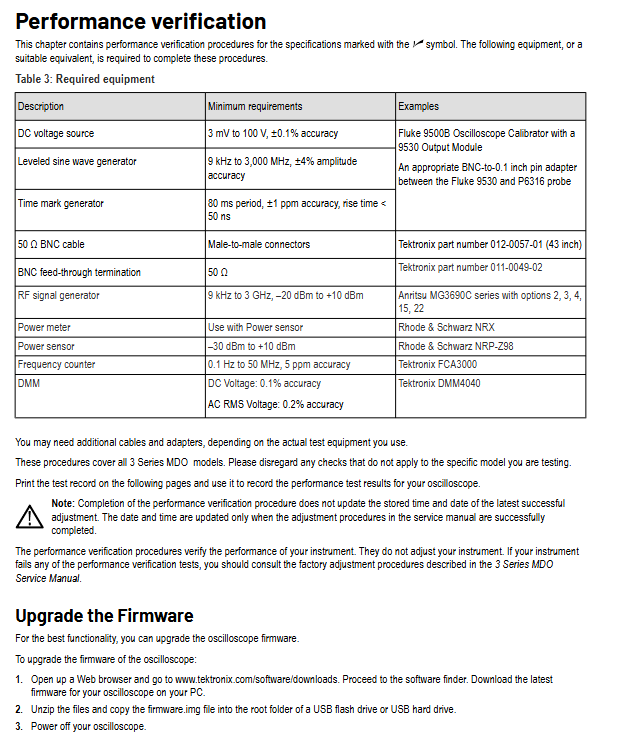
3. List of Testing Equipment (Table 3)
Minimum requirements for device name, example model
DC voltage source 3mV-100V, ± 0.1% accuracy Fluke 9500B (equipped with 9530 module)
Sine wave generator 9kHz-3GHz, ± 4% amplitude accuracy Anritsu MG3690C
Power meter+sensor -30dBm -+10dBm Rhode&Schwarz NRX (with NRP-Z98)
Frequency counter 0.1Hz-50MHz, 5ppm accuracy Tektronix FCA3000
Digital Multimeter (DMM) DC ± 0.1%, AC RMS ± 0.2% Tektronix DMM4040
Safety and Maintenance
1. Safety regulations
Grounding requirements: A 3-pin power cord must be used, and the grounding conductor must be reliably connected to the ground. Disconnecting the grounding is prohibited;
Input restrictions: Maximum 300VRMS (CAT II) for 1M Ω channel, maximum 5VRMS for 50 Ω channel, overvoltage may damage terminal resistance;
Operation taboos: Do not plug or unplug probes/cables with power on, do not use in damp (>90% RH) or explosive environments, and do not operate after removing the instrument cover.
2. Maintenance and Calibration
Firmware upgrade: 1 Download firmware. img from the official website to USB; 2. Turn off the oscilloscope and plug it into a USB port; 3. Automatic upgrade upon startup (power off prohibited);
Calibration cycle: recommended to be 1 year, with a reference frequency error accumulation of ± 10ppm/year (including aging and temperature effects);
Self check and diagnosis: Path: Utility → Self Test. If it fails, it will enter extended diagnosis and can be exited by pressing MENU OFF (it can be temporarily used when the fault does not affect the measurement).
Key issue
Question 1:3: The simulated bandwidth of the 3 series MDO is related to the vertical gear. What is the actual bandwidth of the 1GHz model at different vertical gears? How to confirm whether the bandwidth is qualified through performance verification?
Answer:
1、 Actual bandwidth of different vertical gears for 1GHz models
The simulated bandwidth of the 1GHz model decays with decreasing vertical gear, and the specific corresponding relationship is as follows:
Vertical gear (Volts/Div) 50 Ω input bandwidth 1M Ω input bandwidth (typical value)
10mV/div - 1V/div DC - 1.0GHz DC - 1.0GHz
5mV/div - 9.98mV/div DC - 500MHz DC - 500MHz
2mV/div - 4.98mV/div DC - 350MHz DC - 350MHz
1mV/div - 1.99mV/div DC - 150MHz DC - 150MHz
2、 Bandwidth performance verification steps (taking 50 Ω input as an example)
Equipment connection: Connect a sine wave generator (such as Fluke 9500B) to oscilloscope channel 1 via a 50 Ω coaxial cable, with the generator output impedance set to 50 Ω;
Oscilloscope settings:
Reset according to Default Setup;
Set the Acquisition Mode to Sample;
Add peak to peak measurement (Measure → Amplitude → Peak to Peak → Add);
Channel 1 setting: Termination=50 Ω, Vertical Scale=corresponding test gear (such as 1mV/div);
Signal input: The generator outputs a 10MHz sine wave, adjust the amplitude to display 8div on the screen (such as outputting 8mVpp at 1mV/div level), and record the peak value (Vin pp) at this time;
Bandwidth test: Adjust the generator frequency to the maximum bandwidth corresponding to this gear (e.g. 1mV/div corresponds to 150MHz), and record the peak value (Vbw pp) at this time;
Qualification judgment: Calculate the gain as Vbw-pp/Vin pp. If the gain is ≥ 0.707 (-3dB point), the bandwidth is qualified.
Question 2: How to test the threshold accuracy of the digital channel (3-MSO option) of the 3 series MDO? What are the key operational details to pay attention to during testing?
Answer:
1、 Testing steps for threshold accuracy of digital channels
Equipment preparation: DC voltage source (such as Fluke 9500B), P6316 digital probe, BNC-to-0.1 inch pin adapter;
Probe connection: P6316 probe Group 1 is connected to a voltage source, and an adapter is used to match the interface;
Oscilloscope settings:
Reset according to Default Setup;
Activate the digital channel (D15-D0 button → Turn All On);
Set digital channel threshold (such as 0V or 4V): D15-D0 menu → Thresholds → Enter target value;
Trigger setting: Trigger → Source=Target digital channel (such as D0), Slope=Rising/Falling;
Threshold measurement (taking 0V threshold as an example):
Vs - (high to low switching voltage): Set the voltage source to -400mV, gradually increase by 20mV until the channel displays a stable low level (blue), and record the voltage as Vs - at this time;
Vs+(low to high switching voltage): Set the voltage source to+400mV, gradually -20mV until the channel displays a stable high level (green), and record the voltage as Vs+at this time;
Calculate the average threshold: VSAvg=(Vs -+Vs+)/2;
Qualification judgment: The 0V threshold must meet the requirement of * * -0.1V ≤ VSAvg ≤ 0.1V * *, and the 4V threshold must meet the requirement of 3.78V ≤ VSAvg ≤ 4.22V.
2、 Key operational details
Probe grounding: All 8 grounding channels of P6316 probe need to be connected to user grounding to avoid threshold deviation caused by poor grounding;
Voltage stepping: After adjusting the voltage each time, wait for 3 seconds to ensure that the channel state is stable before recording to avoid transient interference;
Trigger slope switching: When measuring Vs -, use the Rising slope, and when measuring Vs+, use the Falling slope to ensure that the trigger point is consistent with the level switching;
Multi channel testing: After testing each channel (such as D0), set its Display to Off and activate the next channel (such as D1) to avoid interference between channels.
Question 3: How to test the display average noise level (DANL) in the spectrum analyzer function of the 3 series MDO? What are the DANL qualification standards for different frequency ranges?
Answer:
1、 DANL testing steps (no input signal, only 50 Ω terminal required)
Equipment connection: oscilloscope RF input connected to 50 Ω feedthrough terminal, no external signal input;
Oscilloscope settings:
Reset according to Default Setup;
Activate RF channel (RF button → On);
Set Trace mode: RF menu → Traces → Average=On, Normal=Off;
Detection mode: Detection Method → Manual → Average;
Reference level: Vertical Settings → Ref Level=-15dBm;
Frequency range setting and measurement:
9kHz-50kHz: Orizontal → Start=9kHz, Stop=50kHz, move the Marker (Multipurpose knob a) to the highest noise point, and record the DANL value;
50kHz-5MHz:Start=50kHz,Stop=5MHz,Center=2.525MHz, Record the highest noise level;
5MHz-2GHz (3-SA3 option): Start=5MHz, Stop=2GHz, Center=1GHz, Span=10MHz, record the highest noise value;
2GHz-3GHz (3-SA3 option): Start=2GHz, Stop=3GHz, Center=2.5GHz, Span=10MHz, record the highest noise value;
Data processing: Ignore stray signals above the noise level (refer to the "residual response" specification) and only record the noise baseline value.
2、 DANL qualification standards for different frequency ranges
Frequency range standard (without 3-SA3) 3-SA3 option typical values (better than standard)
9kHz-50kHz ≤-109dBm/Hz ≤-109dBm/Hz ≤-113dBm/Hz
50kHz-5MHz ≤-126dBm/Hz ≤-126dBm/Hz ≤-130dBm/Hz
5MHz-1GHz ≤-136dBm/Hz ≤-136dBm/Hz ≤-140dBm/Hz
1GHz-2GHz - ≤-136dBm/Hz ≤-140dBm/Hz
2GHz-3GHz - ≤-126dBm/Hz ≤-130dBm/Hz
3、 Testing precautions
Terminal matching: A 50 Ω terminal must be used, otherwise impedance mismatch may cause high noise measurement;
Stray elimination: If there is significantly higher than the base noise at a certain frequency point (such as 1.25GHz, 2.5GHz), the noise values on both sides of the noise should be recorded, rather than the noise itself;
Average time: In the low-frequency range (such as 9kHz-50kHz), wait for 60 seconds to ensure that the average trace is stable before reading.
- YOKOGAWA
- Reliance
- ADVANCED
- SEW
- ProSoft
- WATLOW
- Kongsberg
- FANUC
- VSD
- DCS
- PLC
- man-machine
- Covid-19
- Energy and Gender
- Energy Access
- Renewable Integration
- Energy Subsidies
- Energy and Water
- Net zero emission
- Energy Security
- Critical Minerals
- A-B
- petroleum
- Mine scale
- Sewage treatment
- cement
- architecture
- Industrial information
- New energy
- Automobile market
- electricity
- Construction site
- HIMA
- ABB
- Rockwell
- Schneider Modicon
- Siemens
- xYCOM
- Yaskawa
- Woodward
- BOSCH Rexroth
- MOOG
- General Electric
- American NI
- Rolls-Royce
- CTI
- Honeywell
- EMERSON
- MAN
- GE
- TRICONEX
- Control Wave
- ALSTOM
- AMAT
- STUDER
- KONGSBERG
- MOTOROLA
- DANAHER MOTION
- Bentley
- Galil
- EATON
- MOLEX
- Triconex
- DEIF
- B&W
- ZYGO
- Aerotech
- DANFOSS
- KOLLMORGEN
- Beijer
- Endress+Hauser
- schneider
- Foxboro
- KB
- REXROTH
- YAMAHA
- Johnson
- Westinghouse
- WAGO
- TOSHIBA
- TEKTRONIX
- BENDER
- BMCM
- SMC
- HITACHI
- HIRSCHMANN
- XP POWER
- Baldor
- Meggitt
- SHINKAWA
- Other Brands
- UniOP
- KUKA
- IBA
- Beckhoff
-
ADLINK CPCI-6860A - 51-31310-OB10 industrial motherboard CompactPCI SBC
-
ADLINK AmITX-SL-G-H110 - 51-7A104-0A30 Mini-ITX Industrial Motherboard
-
ADLINK PXI-2005-003 - CPCI Industrial PC Data Acquisition Card Multi-Function DAQ
-
ADLINK DININ-814M - 51-14032-0A3D SCSI-100P cable connection Interface Terminal Board
-
ADLINK CPCI-3920NA/C2D15/M1G - 3U CompactPCI Intel Core 2 Duo Single Board Computer
-
ADLINK PCIE-8560 - 51-18014-0A20 Communication Card High Speed DAQ
-
ADLINK PCI-C154+ - Motion Control Card 4-axis Motion Controller Board
-
ADLINK PCI-RTV24 - image capture card Analog Video Frame Grabber
-
ADLINK NuPRO-842LV/P - 51-41360-0B30 Industrial Motherboard CPU Board
-
ADLINK cBP-3208/3208R - CPCI Board 3U 8-Slot CompactPCI Backplane
-
ADLINK PCI-8164 - 4-Axis Motion Controller PCI Card 51-12406-0A40
-
ADLINK PCIe-GIE64+ - 4-CH GigE Vision PoE+ Frame Grabber Video Capture Card
-
ADLINK CPCI-6860 / 6860A - CompactPCI Dual Xeon Single Board Computer
-
ADLINK IEC-915GV - REV 1.1 Industrial motherboard CPU Board
-
ADLINK ND-6520 - Technology RS-232 to RS-422RS-485 Converter NuDAM Module
-
ADLINK RTV-24 / PCI-MP4S - 51-12519-1C30 4-Channel Real Time Video Capture Board
-
ADLINK cPCI-6910 / cPCI-6910AM/M1G - cPCI-6910AM/DXL16/M1G/S80G(G)-3120 BOARD CompactPCI SBC
-
ADLINK NUPRO-A40H - Linghua 51-41807-1A30 Industrial Control Computer Motherboard
-
ADLINK USB-3488A - USB to GPIB INTERFACE USB-3488A(G) Controller Module
-
ADLINK PCI-8134A - motion control card 4-Axis Controller Card
-
ADLINK PCI-7432 - Board 32-Channel input / 32-output Isolated Digital I/O PCI Card
-
ADLINK PCI-8134A - 51-12421-0A10 motion controller card tested
-
ADLINK LPCIe-7230 - 32 CH Isolated Input/output Card 2 Interrupts Low Profile PCIe
-
ADLINK NuPRO-E340 - industrial computer motherboard 51-47807-0A30 PICMG 1.3 SHB
-
ADLINK PCI-7434 - High-speed Digital Acquisition Card 64-CH Isolated DO Card
-
ADLINK NuPRO-E330 - 51-41805-0A20 Indsutrial Board SHB Single Board Computer
-
ADLINK PCI-7248 - OPTO-22 48 CHANNEL DIO DIGITAL TTL/DTL I/O 51-12006-0A40 GP
-
ADLINK PCI-8134 - Motion control card 4-Axis Controller Card
-
ADLINK AMP-208C - Movimiento Control Tarjeta 51-12420-1A20 W/Expansión & Breakout
-
ADLINK PCI-8164 - 51-12406-0A40 PCB Board 4-Axis Motion Controller Card
-
ADLINK DIN-68Y-SGII / DIN-68M-J3A - Terminal Board Connector Interface Block
-
ADLINK PCIe-7432 - Technology 51-18402-0A10 PCIe Card With High Input Range
-
ADLINK PCI-8144 / PCI-8144N - Motion control card 4-Axis Stepper Controller Card
-
ADLINK HSL-HUB3/REPEATER - HIGH SPEED LINK EXTENSION MODULES Distributed Hub Module
-
ADLINK ND-6017 - Data Logging + Acquisition 8CH A/D input Mod NuDAM Module
-
ADLINK LPCIe-7250 - data acquisition card Low Profile 8-CH Relay Output Card
-
ADLINK PCI-7432 - I/O card 64-CH Isolated Digital Input Output PCI Card
-
ADLINK IMB-M43H - industrial control computer motherboard Q87 Chip Micro-ATX
-
ADLINK MP-C154 - Motion control Card 4-Axis Motion Controller Board
-
ADLINK PCI-RTV24 - image capture card Video Frame Grabber Card
-
ADLINK PCI-7250 - 8-CH Relay Output & 8-CH Isolated DI Card
-
ADLINK PCI-6308V - 8-CH 12-Bit Isolated Analog Output PCI Card PCB-I-E-1148=6EX2
-
ADLINK PCI-7248 - capture card 48-CH Opto-22 Compatible DIO Card
-
ADLINK HSL-AI16A02-M-VV - Analog Input Output Distributed Module
-
ADLINK NuPRO-A301 - Rev:1.4 NUPRO-A301 PICMG Full-Size Single Board Computer
-
ADLINK PCI-6208V-GL - 8-CH Voltage Analog Output PCI Card
-
ADLINK PCI-8134A - 51-12421-0A10 4-Axis Motion Controller Card
-
ADLINK MNET-S23 - TECHNOLOGY MNET S23 - SERVO DRIVER CONTROL MODULE
-
ADLINK M-342 - ATX I3 I5 I7 Q67 Industrial Motherboard
-
ADLINK NUPRO-780 - Industrial Motherboard CPU Board PICMG SBC
-
ADLINK MP-C154 / MP-C152 - 4-Axis Motion Control Card Pulse-Train Controller
-
ADLINK NuPRO-935A/LV10B0 - Motherboard 51-41802-0A10 GP w/RAM Industrial Control Board
-
ADLINK MP-C154 - Motion control card 4-Axis Motion Controller Mainboard
-
ADLINK PCI-7250 - PCI Acquisition Card 8-CH Relay Output Isolated DI Card
-
ADLINK ACL-7124 - Technology Inc.24 DIO Card Digital Input Output Card
-
ADLINK PCI-8554 A2 - Timer/Counter Data Acquisition Card
-
ADLINK DIN-825-GP4 - Terminal Block Interface Board Breakout Module
-
ADLINK NuPR0-761 - REV:1.1 Industrial motherboard Full-Size PICMG SBC
-
ADLINK MXE-1401/M8G (G) - Matrix Fanless Embedded Computer Industrial PC
-
ADLINK HSL-DI16DO16-UD-NN - Digital 16 Channel I/O Mod Distributed I/O Module
-
ADLINK ND6520 - NUDAM INTELLIGENT DA&C MODULE RS232-RS-422/RS485 CONVERTOR
-
ADLINK NUPRO-761 - REV:1.1 Industrial Motherboard CPU Board
-
ADLINK AMP-208C - Motion Control Card 51-12420-1A20 DSP-based 8-axis
-
ADLINK NuPRO-A301REV 1.4 - with packaging industrial computer motherboard PICMG SBC
-
ADLINK PCM-9112+ - 51-12300-0A2 industrial motherboard Multi-Function DAQ PC/104 Module
-
ADLINK PCM-7250+ - 8-CH Relay Outputs & 8-CH Isolated DI Module PC/104
-
ADLINK PCI-RTV24 - Image capture card Analog Video Frame Grabber
-
ADLINK PCI-8134 - Motion Controller PCI Card 4-Axis Controller Board
-
ADLINK PCI-7432 - Isolated Digital I/O PCI Card
-
ADLINK PCI-8554 A2 - acquisition card Timer/Counter Card
-
ADLINK PCI-8132 - Rev.A2 2-Axis Servo & Stepper Motion Controller Card
-
ADLINK PCI-8132 - Data Acquisition card 2-Axis Motion Controller Card
-
ADLINK EBP-13E4 - 51-46703-0A30 Industrial Backplane Board Passive Backplane
-
ADLINK PCI-800L - Electronic Card Interface Controller Card
-
ADLINK PCIe-GIE72 - 51-18531-0A10 PCB Board GigE Vision Frame Grabber
-
ADLINK DAQ-2010(G)-OOBO - Simultaneous-Sampling Multi-Function DAQ Card
-
ADLINK PCI-9112 - REV.B1 Multifunction DAQ Card Data Acquisition Card
-
ADLINK PCI-7230 - 51-12003-DA60 32-CH Isolated Digital I/O Card
-
ADLINK PCI-7432 - Data Acquisition Card Isolated Digital I/O PCI Card
-
ADLINK ETX-AT-N270-18/LXE - 51-71111-0A20 ETX CPU Module Motherboard
-
ADLINK HSL-DI32-UD-N - DIGITAL INPUT 32 POINTS MODULE Distributed I/O
-
ADLINK AMP-204C - Motion Control card DSP-Based 4-Axis Advanced Controller
-
ADLINK MNET-4XMOG-0050 - Four-axis Motion Controller Distributed Motion Module
-
ADLINK AMP-204C - Motion control card DSP-Based 4-Axis Pulse-Train Controller
-
ADLINK PCI-7442 - Switch card 64-Channel Datalogging & Acquisition Card
-
ADLINK M-302 - Industrial control motherboard ATX PC Board
-
ADLINK NUPRO-852 / NUPRO-852LV - Industrial motherboard Single Board Computer
-
ADLINK PCI-8134 - REV.B1. 4-Axis Motion Controller Card
-
ADLINK PCI-GIE62 + - 51-18502-0A20 2-CH GigE Vision Frame Grabber PoE Card
-
ADLINK PCI-MPG24 - 51-12523-0B20 MPEG4 Card Video Compression Hardware
-
ADLINK HSL-TB32-M-DIN - 32-CH I/O TERMINAL W/ HSL-AI16AO2-M-VV MODULE
-
ADLINK PCI-M114-GL - PCB Ver 2.1 Motion Controller Axis Card
-
ADLINK IMB-M40H - SYM76996H61 motherboard Industrial Computer Mainboard
-
ADLINK NUPRO-A40H - 51-41807-1A20 industrial control motherboard H61 Chip
-
ADLINK PCI-M114-GL - Axis Card Data Acquisition Card PCB VER2.2 Motion Controller
-
ADLINK PCI-8134 - Motion Controller PCI Card 4-Axis Controller Board
-
ADLINK PCI-8102 - Motion control card 2-Axis Servo & Stepper Controller
-
ADLINK NuPRO-841REV:3.0 - motherboard Industrial Control PC Board
-
ADLINK HSL-TB32-U-DIN REV A1 - Breakout Terminal Board Field I/O Module
-
ADLINK AMP-204C - Motion Control card DSP-Based 4-Axis Pulse-Train Controller
-
ADLINK NUPRO-A40H - 51-41807-1A20 industrial control motherboard H61 PC Board
-
ADLINK PCI-6308A / PCI-6308V - 51-12202-0A50 Isolated Analog Output Card
-
ADLINK AMP-204C - DSP-Based 4-Axis Advanced Pulse-Train Motion Controller
-
ADLINK PCI-7434 - Technology 64-Channel Isolated Digital I/O PCI Cards
-
ADLINK CPCI-6840 / CPCI-6840V / PM16/M1G-12G0 - CompactPCI Single Board Computer CPU Module
-
ADLINK PCIE-GIE74 - Motherboard Video Capture Card 51-18531-0A10 Frame Grabber
-
ADLINK NuPRO-E330 - industrial computer equipment motherboard Control Mainboard
-
ADLINK AMP-208C / 51-12420-1A20 - Motion Control Card W/ Expansion & Breakout Board
-
ADLINK HPCI-14S12U - industrial computer baseboard Passive Backplane 14 Slots
-
ADLINK PCI-8164 - 4-Axis Motion Controller PCI Card W/ 1x Cable, 1x Breakout Box
-
ADLINK PCIe-RTV24 - 51-18016-0A20 Image Acquisition Video Capture Card
-
ADLINK M-342 - 5 PCI ATX Motherboard Industrial PC Mainboard
-
ADLINK PCI-FIW64 - 4/2 Channel IEEE1394B Image Capture Card FireWire Frame Grabber
-
ADLINK PCI-7432 - digital IO card 64-CH Isolated Digital Input Output Card
-
ADLINK 51-12001-0C20 - Circuit Board PCI-7200 Data Acquisition Controller Card
-
ADLINK PXI-3920 - PXI 3U cPCI Industrial Controller Embedded System CPU Board
-
ADLINK NuPRO-841REV:2.0 - motherboard Industrial Control PC Board
-
ADLINK NuPro-E330 - 51-41805-0A20 PCB Industrial Control Computer Motherboard
-
ADLINK PCI-RTV24 - Image capture card Analog Video Frame Grabber
-
ADLINK PCI-7442 - Switch card 64-Channel Datalogging & Acquisition Card
-
ADLINK HPX-13S4 - device baseboard Passive Backplane Riser Card
-
ADLINK PCI-9112 REV A.1 - Multi Function DA&C Board Data Acquisition Card
-
ADLINK PCI-7248 - 51-12006-0A40 Card Control 48-CH Digital I/O Module
-
ADLINK CPCI-6860 / 6860A - motherboard CompactPCI Dual Xeon Single Board Computer
-
ADLINK DPAC-3020-11(G) - Embedded PC Automation Controller Machine Control Board
-
ADLINK NuPRO-841 REV:1.0 - industrial control motherboard CPU Board
-
ADLINK MNET-4XMOG-0050 - Four-axis Motion Controller MNET Motion Control Card
-
ADLINK ETX-AT-N270-18/LXE - 51-71111-0A20 ETX CPU Module Motherboard

K-JIANG

Add: Jimei North Road, Jimei District, Xiamen, Fujian, China
Tell:+86-15305925923