
K-WANG


Tektronix 2440 digital oscilloscope
Tektronix 2440 digital oscilloscope
Document Overview
This document is a quick reference guide for the Tektronix 2440 digital oscilloscope, first printed in 1987. Its core positioning is a "practical operation manual" - it does not replace the complete "2440 Operation Manual" (070-6695-00), but focuses on step-by-step operation and menu logic analysis of the instrument's core functions. The document structure is centered around the "front control panel buttons" and follows the process of "basic power on → functional modules → data output". It covers 19 key functional chapters, including 19 hardware schematics and menu screenshots, clarifying the hierarchical menu relationship, parameter adjustment range, and typical application scenarios of each button. It is suitable for engineers who have already understood the basic principles of oscilloscopes and need to quickly get started, especially focusing on practical guidance for characteristic functions such as dual trigger systems, multi-mode acquisition, GPIB communication, etc.

Core parameters and hardware layout of the instrument
2.1 Core Technical Parameters
Detailed Explanation of Key System Parameters
Vertical system channel configuration with 2 analog channels (CH1/CH2), supporting ADD/MULT/XY combination mode
Sensitivity range 2mV/div -5V/div (equivalent to 20mV/div -50V/div after 10X probe adaptation)
Coupling method AC/DC/GND, AC coupling and 50 Ω terminal mutually exclusive
The bandwidth limit is adjustable in three levels: 20MHz/100MHz/FULL, and can be extended to 300MHz in Repet mode (only repeating waveforms)
Horizontal system time base range A/B dual time base, 5ns/div -100ms/div, ≤ 100ms/div automatically switches to ROLL mode
Trigger positions 1/8, 1/4, 1/2, 3/4, 7/8, a total of 5 preset positions, supporting GPIB custom positions
Trigger system trigger type A/B dual trigger, supporting Edge/Video/Word/Pulse trigger (Video/Word requires optional)
Coupling method DC/AC/Noise Reject/LF Reject/HF Reject, adapted to different signal noise environments
There are a total of 5 collection modes for the collection system: Normal/Average/Explore/Repet/Save On Delta
Average frequency 2/4/8/16/32/64/128/256 times optional
The storage system has four independent reference memories (REF1-REF4), which support waveform freezing and calling
The GPIB communication interface supports Talk/Lite mode and is compatible with printer/plotter data output
2.2 Core Layout of Front Control Panel (Divided by Function)
(1) Display control area
INTENSITY knob: continuously adjusts the brightness of 4 types of screen elements (reading readout, waveform display, A INTEN area, scale texture), and defaults to controlling the last selected element;
SELECT button: Switch brightness adjustment object (read out) ↔ display);
STATUS/HELP button: Press once to display the "Instrument Status Menu" (including trigger status, acquisition mode, parameter configuration), press again to enter HELP mode (operate any button to display the corresponding function description).
(2) Quick operation area
AUTO SETUP button: One click optimization of vertical/horizontal/trigger parameters to ensure stable signal display (default activation of CH1, no switching for selected channels);
PRGM button: Enter the "AutoStep Sequencer" menu, support storing/calling 50-200 panel settings, and can name 40 test processes;
MEASURE button: activates waveform parameter extraction function, supports continuous measurement or single snapshot;
OUTPUT button: Configure GPIB communication parameters, control data transmission/printing/drawing.
(3) Vertical control zone
CH1/CH2 independent control:
POSITION knob: adjust the vertical position of the channel waveform;
VARIABLE button: Unlock non calibration adjustment (CH1 affects ADD mode reading, CH2 does not affect);
VOLTS/DIV knob: adjusts sensitivity (2mV-5V/div), automatically adapts to 1X/10X/100X/1000X Tek encoding probes;
COUPLING/INVERT button: switch coupling mode, reverse waveform polarity;
BANDWIDTH button: Select the bandwidth limit gear.
MODE button: Switch vertical mode (CH1/CH2/ADD/MULT/YT: XY), ADD and MULT are mutually exclusive. In XY mode, CH1 is the X-axis and CH2 is the Y-axis.
(4) Horizontal control zone
A/B button: Switch between A/B time base mode (A is the regular time base, B is the delayed scan);
A INTEN button: Activate A enhancement mode, SEC/DIV knob switches to control B time base;
A AND B SEC/DIV knob: adjust the time base (5ns-100ms/div);
POSITION knob: Adjust the horizontal position of the waveform and control the CH1 (X-axis) position in XY mode.
(5) Trigger and Delay Control Zone
A/B TRIG button: Switch A/B trigger menu, share trigger slope, mode, source selection and other controls;
TRIGGER LEVEL knob: adjust trigger level;
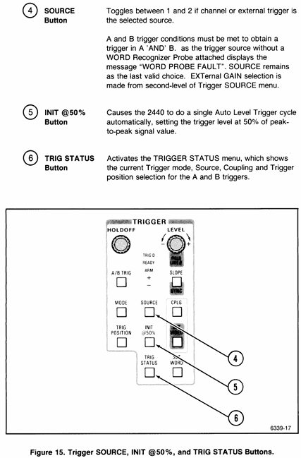
Initiat @ 50% button: automatically sets the trigger level to 50% of the signal peak to peak value;
DELAY area: EVENT and TIME buttons, CURSOR/DELAY knobs (adjust delay parameters or cursor position).
(6) Collection and Storage Control Area
ACQUIRE button: start/restart acquisition, switch acquisition mode;
SAVE button: Freeze waveform, enter storage menu;
Display REF button: Call the reference waveform (REF1-REF4) to switch the horizontal position adjustment mode.
Basic operation process (from startup to signal display)
3.1 Startup and self-test process
Power on preparation: Connect the 3-pin power supply (ensure grounding), press the POWER button below the front panel;
Self check process: The instrument automatically performs a power on self-test, and the screen displays "RUNNING SELF TEST". After completion, the prompt disappears;
Self check passed: directly enter oscilloscope mode, CAL/DIAG menu displays "PASS";
Self check failure: Enter extended diagnostic mode, the screen displays the fault area, press MENU OFF to exit and enter oscilloscope mode (temporary use when the fault does not affect measurement);
Preheating waiting: Within 10 minutes after starting up, the CAL/DIAG menu displays "NOT WARMED UP", during which it is not recommended to perform calibration or high-precision measurements;
Parameter initialization:
Connect probe: 10X probe connected to CH1 BNC, probe tip connected to instrument CALIBRATION circuit( 2.5V@1kHz Square wave), ground wire connected to oscilloscope ground;
Call initial settings: Press PRGM SETUP → press the bezel key (no label button at the bottom of the screen) to select "Initiat PANEL", load default parameters (CH1 activation, 1V/div, 1ms/div, AUTO LEVEL trigger, 1M Ω DC coupling);
Verification channel: Confirm that the CH1 VOLT/DIV reading is displayed in the upper left corner of the CRT. If it is not displayed, press Vertical MODE → Select CH1.
3.2 Signal Capture and Optimization
Signal connection: Connect the probe tip to the measured signal and the ground wire to the signal reference ground (shorten the length of the ground wire as much as possible to reduce noise);
Automatic optimization: Press the AUTO SETUP button, and the instrument will automatically adjust the vertical sensitivity, horizontal time base, and trigger level, displaying 2-5 signal cycles;
Manual fine-tuning:
Vertical adjustment: If the waveform is truncated, turn the VOLTS/DIV knob clockwise (to reduce sensitivity); If the waveform is too small, adjust counterclockwise;
Horizontal adjustment: If the signal period is displayed too much/too little, adjust the SEC/DIV knob (fast time base displays less period, slow time base displays more period);
Trigger optimization: If the trigger is unstable, press Initiat @ 50% or manually turn the TRIGGER LEVEL knob to ensure that the trigger point is on the edge of signal stability.

Detailed analysis of core functions
4.1 Vertical system (signal amplitude control)
4.1. Key functional operations
Coupling mode selection: Press the COUPLING button on CH1/CH2 to cycle through AC/DC/GND:
DC coupling: retaining the AC+DC components of the signal (such as measuring ripple with DC offset);
AC coupling: Block the DC component and only display the AC signal (such as measuring the amplitude of the AC signal);
GND coupling: Disconnect signal input and display ground reference line (used for calibrating vertical position);
ADD/MULT mode usage:
ADD mode: CH1 and CH2 signals are superimposed, and the CH1 VARIABLE knob can adjust the amplitude of CH2 signal to cancel interference (such as eliminating power noise);
MULT mode: The CH1 and CH2 signals are multiplied, and the result is automatically reduced by 5.12 times to adapt to the screen range (such as measuring power signals);
Bandwidth restriction application: When high-frequency noise interference occurs, press the BANDWIDTH button to select 20MHz/100MHz restriction to filter out high-frequency noise (such as selecting 20MHz bandwidth when measuring 50Hz power signals).
4.1.2 Common problem troubleshooting
No waveform display: Check if the coupling mode is GND → switch to AC/DC; Check if the probe is securely connected → Re plug and unplug the probe;
Waveform truncation: VOLTS/DIV sensitivity is too high → adjust clockwise to increase the gear;
High waveform noise: switch to AC coupling → enable bandwidth limitation → shorten the length of the probe ground wire.
4.2 Horizontal System (Signal Timing Control)
4.2.1 A/B dual time base operation
A time base (regular mode): Press the A button to activate, adjust the time base with SEC/DIV knob, and when ≤ 100ms/div, the AUTO trigger mode will automatically switch to ROLL mode (waveform scrolling display from left to right, suitable for slow signals);
B time base (delayed scan):
Press the B button to activate, and switch the SEC/DIV knob to control the B time base;
Adjust the A time base to display the complete signal, and adjust the B time base to amplify the signal locally (such as amplifying the rising edge of the pulse);
Press the A INTEN button, and the screen will display the A enhanced area (the local signal amplified by the B time base) for easy observation of details.
4.2.2 Trigger position adjustment
Press the TRIG POSITION button to cycle through the trigger positions (1/8, 1/4, 1/2, 3/4, 7/8):
Trigger position is 1/8: More display signals after triggering (such as observing the attenuation process after pulse triggering);
Trigger position is 7/8: more display of pre trigger signals (such as capturing interference pulses before triggering);
GPIB customization: Set non preset positions without screen underline identification through GPIB commands.
4.3 Trigger System (Stable Signal Display Core)
4.3.1 A/B Dual Trigger System Logic
A trigger is the "main trigger" (the initial condition for initiating data collection), and B trigger is the "delayed trigger" (further filtering of signals after the main trigger). It supports a combination of "main trigger+delayed event/time" trigger and is suitable for capturing signals with specific temporal relationships.
4.3.2 Detailed Explanation of Trigger Modes
Trigger Mode Function Description Applicable Scenarios
AUTO LEVEL automatically adjusts the trigger level to ensure stable display. Even when the signal disappears, regular signals (sine wave/square wave) can still be scanned for quick debugging
Stable triggering when the AUTO signal is present, and stopping scanning when the signal disappears requires clarification of the scene where the signal is present or absent
NORMAL is only triggered when the triggering conditions are met, and when there is no signal, the screen blank captures rare events (such as occasional pulses)
SINGLE SEQ single acquisition, automatically enters SAVE mode after completion to capture single transient signals (such as relay action)
4.3.3 Special triggering function (requires optional support)
Video trigger:
Press the SET Video button to enter the A Video COUPLING menu;
Select synchronization mode (Field 1/Field 2/ALT/TVLINE), only valid for interlaced signals;
Adjust TVLINE to select the trigger wire number, and CLAMP ON/OFF controls whether to clamp the synchronization signal;
Word trigger:
Press the SET WORD button to enter the Word Recognizer configuration menu;
Select encoding (OCT/HEX), clock signal (CLK), trigger word (such as 0x1234);
Only supports Word recognition probes, displaying "WORD PROBE FAULT" when there is no probe.
4.4 Delay function (capturing specific signals after triggering)
4.4.1 Delay by Events
Function: After A triggers, wait for a specified number of B triggering events before completing the collection;
Operation steps:
Press the DELAY → EVENT button to activate the event delay;
Rotate the CURSOR/DELAY knob to set the event count (such as 10, which is the 10th B event triggered for collection after A is triggered);
Press the TRIG STATION button and confirm that the trigger status is "ARMED";
Applicable scenario: Capture the Nth data bit after the master clock in bus communication.
4.4.2 DELAY by TIME
Function: After triggering A, delay the specified time before completing the collection, supporting switching between "main delay" and "Δ delay";
Operation steps:
Press the DELAY → TIME button to activate the time delay;
Rotate the CURSOR/DELAY knob to set the delay time (e.g. 100 μ s);
Press the Δ TIME button to switch to Δ delay mode and adjust the delay time increment;
Applicable scenario: Capture fault signals that occur after a delay in triggering (such as voltage attenuation after power is turned off).
4.5 Acquisition System (Signal Sampling and Processing)
4.5.1 Comparison of 5 acquisition modes
Working principle of collection mode, key parameters, applicable scenarios
Normal sampling, taking 1 sample point every interval - stable signal (sine wave/square wave), pursuing real-time performance
Average: After multiple acquisitions, take the average value to reduce random noise. The average number of times to reduce random noise is 2-256 for signals containing noise (power ripple, sensor output)
Envelope records the maximum/minimum sample points collected multiple times, generating envelope numbers: 1-256 times/CONT Observe the range of signal amplitude fluctuations (such as RF signal amplitude modulation)
Repet is only effective for repetitive waveforms, extending bandwidth to 300MHz - high-speed repetitive signals (clock signals, high-frequency pulses)
Save On Delta real-time comparison between live waveform and reference envelope, automatically stores reference memory when exceeding the limit: REF1-REF4 long-term monitoring occasional anomalies (such as ripple mutation, pulse distortion)
4.5.2 Acquisition mode switching and restart conditions
Switching method: Press the ACQUIRE button and select the mode and related parameters (such as average frequency and envelope frequency) from the menu;
Restart condition: The following actions will restart Average/Envelope collection:
Vertical/horizontal mode change;
Channel VOLTS/DIV or vertical position adjustment;
Change in input coupling method;
Trigger mode or slope change;
Press MENU OFF to close the menu;
Delay parameter change (only in Average mode).
4.6 Storage System (waveform saving and calling)
4.6.1 Waveform Storage (SAVE Button)
Storage objects: CH1/CH2/ADD/MULT waveforms, delayed waveforms;
Operation steps:
Press the SAVE button to enter the SAVEREF SOURCE menu;
Select storage source (such as CH1);
Enter the SAVEREF DESTIATION menu and select the storage target (REF1-REF4);
Confirm storage, the screen displays the prompt "STORED";
Special function: Press the STACK REF button, and the waveform will be automatically stored in the preset order to REF1-REF4 (such as CH1 → REF1, CH2 → REF2).
4.6.2 Waveform Call (Display REF Button)
Calling steps:
Press the PLAY REF button to enter the PLAY REF menu;
Select the reference memory to be called (REF1-REF4), and display "EMPTY" when there is no waveform;
After calling, the horizontal position of the reference waveform can be adjusted according to HORIZ POS REF;
XY mode call: Select XYREF and call the XY combination waveform from REF1-REF4.
4.7 Measurement system (waveform parameter extraction)
4.7.1 Overview of Measurement Functions
Measurement type: 17 parameters, covering amplitude, time, and special categories:
Amplitude parameters: Peak to peak value (Pk Pk), maximum value (Max), minimum value (Min), mean (Mean), RMS, overshoot (Ovrsht), undershoot (Undrsht), area (Area);
Time parameters: Period, Freq, Rise, Fall, Width, Duty, Delay;
Special parameters: Events, Slope, 1/TIME (reciprocal frequency);
Measurement methods: continuous measurement (MEAS TYPE), single snapshot (SNAPSHOT).
4.7.2 Typical Measurement Operations (Taking "Rise Time" as an Example)
Preparation work: Ensure stable signal triggering, no obvious noise on the rising edge, and horizontal time base adaptation (such as measuring ns level rise time using 5ns/div);
Enter the measurement menu: press the Measure button;
Select measurement type: Press MEAS TYPE → check "RISE" in the parameter matrix;
Set measurement standards (default 10% -90%, customization requires SETUP → LEVEL):
Rotate the knob to adjust the levels of DISTAL (corresponding to 10%) and PROXIMAL (corresponding to 90%);
Press the MARK ON button, and the screen will display measurement markers (X-shaped) indicating the 10% and 90% level positions;
Reading result: The screen measurement reading area displays the rise time value (such as 28.4ns);
Single snapshot: Press SNAPSHOT → select the target channel (such as CH1), and the instrument captures all parameters of the current waveform and freezes the display.
4.8 GPIB Communication and Data Output (OUTPUT Button)
4.8.1 GPIB parameter configuration
Enter the configuration menu: press OUTPUT → SETUP;
Core parameter settings:
Mode: T/ONLY (only sends data), L/ONLY (only receives commands), T/L (sends and receives), DEVICES (connects to printer/plotter), OFF BUS (turns off GPIB);
Address (ADDR): Set GPIB address (such as 3) to match the controller address;
Terminator (TERM): EOI (default) LF/EOI, Ensure consistency with the receiving device;
Encoding (ENCDG): ASCII, RP (positive integer), RI (default), positive integer data should be set to RP;
Device adaptation: Press DEVICES → select device type (HPGL plotter, THINKJET printer) → set paper size (US: A4), whether to display scale (GRAT ON/OFF).
4.8.2 Data Transmission and Status Monitoring
Sending data: Press the TRANSMIT/RINT button to send the current waveform (CURVE), panel settings (PRGM), or measurement results to an external device;
Status monitoring: Press OUTPUT → STATUS to check the GPIB status (such as address, mode, error messages), with the undersigned item indicating the current effective setting;
Troubleshooting: If data transmission fails, check:
Is the GPIB cable connection secure;
Whether the address, terminator, and code are consistent with the receiving device;
Does the device support the selected data format (such as WHOLE WFMS/ARTIAL WFMS).
Safe operation and precautions
5.1 Safety prerequisites
It is necessary to refer to the "Operator Safety Summary" in the 2440 Operation Manual, with a focus on:
Input voltage limit: maximum 400Vpk for 1M Ω coupling, maximum 5Vrms for 50 Ω coupling;
Probe usage: Only use Tek recommended probes (such as 10X passive probes), and the probe ground wire must not be connected to mains power;
Grounding requirements: The instrument must be grounded through a 3-pin power supply and disconnection of the grounding pin is prohibited;
Do not use in damp or explosive environments, and do not plug or unplug probes or signal cables with power on.
5.2 Maintenance and Calibration
Signal Path Compensation (SPC): If the environmental temperature difference exceeds 10 ℃ or once a week, follow Utility → Calibration → Signal Path, which takes about 10 minutes to ensure low range (≤ 5mV/div) measurement accuracy;
Probe compensation: Every time the probe or channel is replaced, a CALIBRATOR circuit needs to be connected( 2.5V@1kHz )Adjust the compensation hole of the probe to a straight square wave;
Calibration prompt: If the extended diagnosis displays "UNCALD", perform a SELF CAL after the instrument is preheated. If it still fails, contact a professional for calibration. At this time, the instrument may use the previous calibration parameters, and the measurement accuracy may decrease.
5.3 Common troubleshooting
Troubleshooting steps for possible causes of fault phenomena
No waveform display 1. Channel not activated; 2. The coupling method is GND; 3. Unstable triggering; 4. The brightness setting is too low. 1. Press MODE to activate the corresponding channel; 2. Switch the coupling to AC/DC; 3. Press AUTO SETUP or Initiat @ 50%; 4. Adjust the INTENSITY knob
Unstable triggering: 1. Improper triggering level; 2. The coupling method is not adapted; 3. Excessive signal noise. 1. Manually adjust TRIGGER LEVEL; 2. Enable Noise Reject coupling; 3. Switch to Average acquisition mode
Abnormal measurement result: 1. waveform truncation; 2. Inappropriate adaptation of time base/sensitivity; 3. Measurement standard error: 1. Adjust VOLTS/DIV to avoid waveform truncation; 2. Adapt to time base/sensitivity; 3. Adjust the measurement level by pressing MEASURE → SETUP
GPIB communication failure: 1. Address/code mismatch; 2. Cable malfunction; 3. Equipment not ready. 1. Check GPIB parameters; 2. Replace the cable; 3. Confirm that the external device is in a ready state
- YOKOGAWA
- Reliance
- ADVANCED
- SEW
- ProSoft
- WATLOW
- Kongsberg
- FANUC
- VSD
- DCS
- PLC
- man-machine
- Covid-19
- Energy and Gender
- Energy Access
- Renewable Integration
- Energy Subsidies
- Energy and Water
- Net zero emission
- Energy Security
- Critical Minerals
- A-B
- petroleum
- Mine scale
- Sewage treatment
- cement
- architecture
- Industrial information
- New energy
- Automobile market
- electricity
- Construction site
- HIMA
- ABB
- Rockwell
- Schneider Modicon
- Siemens
- xYCOM
- Yaskawa
- Woodward
- BOSCH Rexroth
- MOOG
- General Electric
- American NI
- Rolls-Royce
- CTI
- Honeywell
- EMERSON
- MAN
- GE
- TRICONEX
- Control Wave
- ALSTOM
- AMAT
- STUDER
- KONGSBERG
- MOTOROLA
- DANAHER MOTION
- Bentley
- Galil
- EATON
- MOLEX
- Triconex
- DEIF
- B&W
- ZYGO
- Aerotech
- DANFOSS
- KOLLMORGEN
- Beijer
- Endress+Hauser
- schneider
- Foxboro
- KB
- REXROTH
- YAMAHA
- Johnson
- Westinghouse
- WAGO
- TOSHIBA
- TEKTRONIX
- BENDER
- BMCM
- SMC
- HITACHI
- HIRSCHMANN
- XP POWER
- Baldor
- Meggitt
- SHINKAWA
- Other Brands
- UniOP
- KUKA
- IBA
- Beckhoff
-
ADLINK CPCI-6860A - 51-31310-OB10 industrial motherboard CompactPCI SBC
-
ADLINK AmITX-SL-G-H110 - 51-7A104-0A30 Mini-ITX Industrial Motherboard
-
ADLINK PXI-2005-003 - CPCI Industrial PC Data Acquisition Card Multi-Function DAQ
-
ADLINK DININ-814M - 51-14032-0A3D SCSI-100P cable connection Interface Terminal Board
-
ADLINK CPCI-3920NA/C2D15/M1G - 3U CompactPCI Intel Core 2 Duo Single Board Computer
-
ADLINK PCIE-8560 - 51-18014-0A20 Communication Card High Speed DAQ
-
ADLINK PCI-C154+ - Motion Control Card 4-axis Motion Controller Board
-
ADLINK PCI-RTV24 - image capture card Analog Video Frame Grabber
-
ADLINK NuPRO-842LV/P - 51-41360-0B30 Industrial Motherboard CPU Board
-
ADLINK cBP-3208/3208R - CPCI Board 3U 8-Slot CompactPCI Backplane
-
ADLINK PCI-8164 - 4-Axis Motion Controller PCI Card 51-12406-0A40
-
ADLINK PCIe-GIE64+ - 4-CH GigE Vision PoE+ Frame Grabber Video Capture Card
-
ADLINK CPCI-6860 / 6860A - CompactPCI Dual Xeon Single Board Computer
-
ADLINK IEC-915GV - REV 1.1 Industrial motherboard CPU Board
-
ADLINK ND-6520 - Technology RS-232 to RS-422RS-485 Converter NuDAM Module
-
ADLINK RTV-24 / PCI-MP4S - 51-12519-1C30 4-Channel Real Time Video Capture Board
-
ADLINK cPCI-6910 / cPCI-6910AM/M1G - cPCI-6910AM/DXL16/M1G/S80G(G)-3120 BOARD CompactPCI SBC
-
ADLINK NUPRO-A40H - Linghua 51-41807-1A30 Industrial Control Computer Motherboard
-
ADLINK USB-3488A - USB to GPIB INTERFACE USB-3488A(G) Controller Module
-
ADLINK PCI-8134A - motion control card 4-Axis Controller Card
-
ADLINK PCI-7432 - Board 32-Channel input / 32-output Isolated Digital I/O PCI Card
-
ADLINK PCI-8134A - 51-12421-0A10 motion controller card tested
-
ADLINK LPCIe-7230 - 32 CH Isolated Input/output Card 2 Interrupts Low Profile PCIe
-
ADLINK NuPRO-E340 - industrial computer motherboard 51-47807-0A30 PICMG 1.3 SHB
-
ADLINK PCI-7434 - High-speed Digital Acquisition Card 64-CH Isolated DO Card
-
ADLINK NuPRO-E330 - 51-41805-0A20 Indsutrial Board SHB Single Board Computer
-
ADLINK PCI-7248 - OPTO-22 48 CHANNEL DIO DIGITAL TTL/DTL I/O 51-12006-0A40 GP
-
ADLINK PCI-8134 - Motion control card 4-Axis Controller Card
-
ADLINK AMP-208C - Movimiento Control Tarjeta 51-12420-1A20 W/Expansión & Breakout
-
ADLINK PCI-8164 - 51-12406-0A40 PCB Board 4-Axis Motion Controller Card
-
ADLINK DIN-68Y-SGII / DIN-68M-J3A - Terminal Board Connector Interface Block
-
ADLINK PCIe-7432 - Technology 51-18402-0A10 PCIe Card With High Input Range
-
ADLINK PCI-8144 / PCI-8144N - Motion control card 4-Axis Stepper Controller Card
-
ADLINK HSL-HUB3/REPEATER - HIGH SPEED LINK EXTENSION MODULES Distributed Hub Module
-
ADLINK ND-6017 - Data Logging + Acquisition 8CH A/D input Mod NuDAM Module
-
ADLINK LPCIe-7250 - data acquisition card Low Profile 8-CH Relay Output Card
-
ADLINK PCI-7432 - I/O card 64-CH Isolated Digital Input Output PCI Card
-
ADLINK IMB-M43H - industrial control computer motherboard Q87 Chip Micro-ATX
-
ADLINK MP-C154 - Motion control Card 4-Axis Motion Controller Board
-
ADLINK PCI-RTV24 - image capture card Video Frame Grabber Card
-
ADLINK PCI-7250 - 8-CH Relay Output & 8-CH Isolated DI Card
-
ADLINK PCI-6308V - 8-CH 12-Bit Isolated Analog Output PCI Card PCB-I-E-1148=6EX2
-
ADLINK PCI-7248 - capture card 48-CH Opto-22 Compatible DIO Card
-
ADLINK HSL-AI16A02-M-VV - Analog Input Output Distributed Module
-
ADLINK NuPRO-A301 - Rev:1.4 NUPRO-A301 PICMG Full-Size Single Board Computer
-
ADLINK PCI-6208V-GL - 8-CH Voltage Analog Output PCI Card
-
ADLINK PCI-8134A - 51-12421-0A10 4-Axis Motion Controller Card
-
ADLINK MNET-S23 - TECHNOLOGY MNET S23 - SERVO DRIVER CONTROL MODULE
-
ADLINK M-342 - ATX I3 I5 I7 Q67 Industrial Motherboard
-
ADLINK NUPRO-780 - Industrial Motherboard CPU Board PICMG SBC
-
ADLINK MP-C154 / MP-C152 - 4-Axis Motion Control Card Pulse-Train Controller
-
ADLINK NuPRO-935A/LV10B0 - Motherboard 51-41802-0A10 GP w/RAM Industrial Control Board
-
ADLINK MP-C154 - Motion control card 4-Axis Motion Controller Mainboard
-
ADLINK PCI-7250 - PCI Acquisition Card 8-CH Relay Output Isolated DI Card
-
ADLINK ACL-7124 - Technology Inc.24 DIO Card Digital Input Output Card
-
ADLINK PCI-8554 A2 - Timer/Counter Data Acquisition Card
-
ADLINK DIN-825-GP4 - Terminal Block Interface Board Breakout Module
-
ADLINK NuPR0-761 - REV:1.1 Industrial motherboard Full-Size PICMG SBC
-
ADLINK MXE-1401/M8G (G) - Matrix Fanless Embedded Computer Industrial PC
-
ADLINK HSL-DI16DO16-UD-NN - Digital 16 Channel I/O Mod Distributed I/O Module
-
ADLINK ND6520 - NUDAM INTELLIGENT DA&C MODULE RS232-RS-422/RS485 CONVERTOR
-
ADLINK NUPRO-761 - REV:1.1 Industrial Motherboard CPU Board
-
ADLINK AMP-208C - Motion Control Card 51-12420-1A20 DSP-based 8-axis
-
ADLINK NuPRO-A301REV 1.4 - with packaging industrial computer motherboard PICMG SBC
-
ADLINK PCM-9112+ - 51-12300-0A2 industrial motherboard Multi-Function DAQ PC/104 Module
-
ADLINK PCM-7250+ - 8-CH Relay Outputs & 8-CH Isolated DI Module PC/104
-
ADLINK PCI-RTV24 - Image capture card Analog Video Frame Grabber
-
ADLINK PCI-8134 - Motion Controller PCI Card 4-Axis Controller Board
-
ADLINK PCI-7432 - Isolated Digital I/O PCI Card
-
ADLINK PCI-8554 A2 - acquisition card Timer/Counter Card
-
ADLINK PCI-8132 - Rev.A2 2-Axis Servo & Stepper Motion Controller Card
-
ADLINK PCI-8132 - Data Acquisition card 2-Axis Motion Controller Card
-
ADLINK EBP-13E4 - 51-46703-0A30 Industrial Backplane Board Passive Backplane
-
ADLINK PCI-800L - Electronic Card Interface Controller Card
-
ADLINK PCIe-GIE72 - 51-18531-0A10 PCB Board GigE Vision Frame Grabber
-
ADLINK DAQ-2010(G)-OOBO - Simultaneous-Sampling Multi-Function DAQ Card
-
ADLINK PCI-9112 - REV.B1 Multifunction DAQ Card Data Acquisition Card
-
ADLINK PCI-7230 - 51-12003-DA60 32-CH Isolated Digital I/O Card
-
ADLINK PCI-7432 - Data Acquisition Card Isolated Digital I/O PCI Card
-
ADLINK ETX-AT-N270-18/LXE - 51-71111-0A20 ETX CPU Module Motherboard
-
ADLINK HSL-DI32-UD-N - DIGITAL INPUT 32 POINTS MODULE Distributed I/O
-
ADLINK AMP-204C - Motion Control card DSP-Based 4-Axis Advanced Controller
-
ADLINK MNET-4XMOG-0050 - Four-axis Motion Controller Distributed Motion Module
-
ADLINK AMP-204C - Motion control card DSP-Based 4-Axis Pulse-Train Controller
-
ADLINK PCI-7442 - Switch card 64-Channel Datalogging & Acquisition Card
-
ADLINK M-302 - Industrial control motherboard ATX PC Board
-
ADLINK NUPRO-852 / NUPRO-852LV - Industrial motherboard Single Board Computer
-
ADLINK PCI-8134 - REV.B1. 4-Axis Motion Controller Card
-
ADLINK PCI-GIE62 + - 51-18502-0A20 2-CH GigE Vision Frame Grabber PoE Card
-
ADLINK PCI-MPG24 - 51-12523-0B20 MPEG4 Card Video Compression Hardware
-
ADLINK HSL-TB32-M-DIN - 32-CH I/O TERMINAL W/ HSL-AI16AO2-M-VV MODULE
-
ADLINK PCI-M114-GL - PCB Ver 2.1 Motion Controller Axis Card
-
ADLINK IMB-M40H - SYM76996H61 motherboard Industrial Computer Mainboard
-
ADLINK NUPRO-A40H - 51-41807-1A20 industrial control motherboard H61 Chip
-
ADLINK PCI-M114-GL - Axis Card Data Acquisition Card PCB VER2.2 Motion Controller
-
ADLINK PCI-8134 - Motion Controller PCI Card 4-Axis Controller Board
-
ADLINK PCI-8102 - Motion control card 2-Axis Servo & Stepper Controller
-
ADLINK NuPRO-841REV:3.0 - motherboard Industrial Control PC Board
-
ADLINK HSL-TB32-U-DIN REV A1 - Breakout Terminal Board Field I/O Module
-
ADLINK AMP-204C - Motion Control card DSP-Based 4-Axis Pulse-Train Controller
-
ADLINK NUPRO-A40H - 51-41807-1A20 industrial control motherboard H61 PC Board
-
ADLINK PCI-6308A / PCI-6308V - 51-12202-0A50 Isolated Analog Output Card
-
ADLINK AMP-204C - DSP-Based 4-Axis Advanced Pulse-Train Motion Controller
-
ADLINK PCI-7434 - Technology 64-Channel Isolated Digital I/O PCI Cards
-
ADLINK CPCI-6840 / CPCI-6840V / PM16/M1G-12G0 - CompactPCI Single Board Computer CPU Module
-
ADLINK PCIE-GIE74 - Motherboard Video Capture Card 51-18531-0A10 Frame Grabber
-
ADLINK NuPRO-E330 - industrial computer equipment motherboard Control Mainboard
-
ADLINK AMP-208C / 51-12420-1A20 - Motion Control Card W/ Expansion & Breakout Board
-
ADLINK HPCI-14S12U - industrial computer baseboard Passive Backplane 14 Slots
-
ADLINK PCI-8164 - 4-Axis Motion Controller PCI Card W/ 1x Cable, 1x Breakout Box
-
ADLINK PCIe-RTV24 - 51-18016-0A20 Image Acquisition Video Capture Card
-
ADLINK M-342 - 5 PCI ATX Motherboard Industrial PC Mainboard
-
ADLINK PCI-FIW64 - 4/2 Channel IEEE1394B Image Capture Card FireWire Frame Grabber
-
ADLINK PCI-7432 - digital IO card 64-CH Isolated Digital Input Output Card
-
ADLINK 51-12001-0C20 - Circuit Board PCI-7200 Data Acquisition Controller Card
-
ADLINK PXI-3920 - PXI 3U cPCI Industrial Controller Embedded System CPU Board
-
ADLINK NuPRO-841REV:2.0 - motherboard Industrial Control PC Board
-
ADLINK NuPro-E330 - 51-41805-0A20 PCB Industrial Control Computer Motherboard
-
ADLINK PCI-RTV24 - Image capture card Analog Video Frame Grabber
-
ADLINK PCI-7442 - Switch card 64-Channel Datalogging & Acquisition Card
-
ADLINK HPX-13S4 - device baseboard Passive Backplane Riser Card
-
ADLINK PCI-9112 REV A.1 - Multi Function DA&C Board Data Acquisition Card
-
ADLINK PCI-7248 - 51-12006-0A40 Card Control 48-CH Digital I/O Module
-
ADLINK CPCI-6860 / 6860A - motherboard CompactPCI Dual Xeon Single Board Computer
-
ADLINK DPAC-3020-11(G) - Embedded PC Automation Controller Machine Control Board
-
ADLINK NuPRO-841 REV:1.0 - industrial control motherboard CPU Board
-
ADLINK MNET-4XMOG-0050 - Four-axis Motion Controller MNET Motion Control Card
-
ADLINK ETX-AT-N270-18/LXE - 51-71111-0A20 ETX CPU Module Motherboard

K-JIANG

Add: Jimei North Road, Jimei District, Xiamen, Fujian, China
Tell:+86-15305925923