
K-WANG


STOBER POSIDRIVE ® MDS 5000 installation method
STOBER POSIDRIVE ® MDS 5000 installation method
Core Overview
Product positioning: ST Ö BER fifth generation inverter, used for supplying power to servo motors (MDS series) and asynchronous motors (FDS, MDS series), is a restricted sales product and may require anti-interference measures for residential use.
Target audience: Only qualified personnel who have received professional training are allowed to install, debug, and maintain.
Key signs: including 5 levels of safety signs such as DANGER (fatal risk) and Warning (major risk), which must be strictly followed.
Safety points
(1) Hardware security
High voltage protection: Do not open the casing when live. After power failure, wait for ≥ 5 minutes (DC link discharge) before operating the option board.
Grounding and installation: Protective conductors must be connected and installed vertically only in enclosed switchgear (IP20), avoiding installation above heating equipment at ambient temperatures of 0-45 ° C (overheating requires derating).
Circuit limitation: The motor needs to be equipped with temperature monitoring or overload protection, only copper wire is used, and the wire cross-section meets NEC standards. Objects are prohibited from entering the interior of the equipment.
(2) Software specifications
POSITool software: licensed for use only, can adjust parameters, monitor signals, prohibit reverse compilation or subleasing, ST Ö BER only maintains the latest two program versions.
Core technical parameters
(1) General parameters
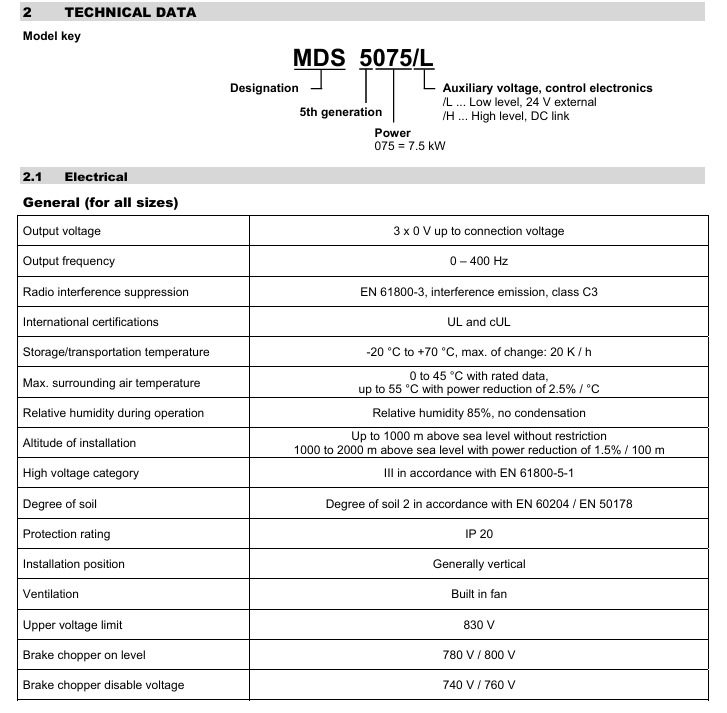
Parameter Value
Protection level IP20
High voltage category EN 61800-5-1 Class III
Maximum voltage 830V
Brake chopper disabled voltage 740V/760V
Motor cable length ≤ 50m (over 50m requires derating)
(2) Key parameters of specifications (partial)
Recommended specifications: motor power, rated current (servo mode), brake resistor adaptation
BG0 (MDS 5015) 1.5kW 3 × 3.0A 200 Ω (maximum 3.2kW)
BG1 (MDS 5075) 7.5kW 3 × 10A 47 Ω (maximum 13.6kW)
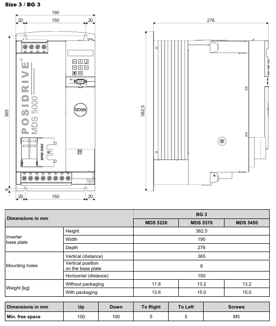
BG3 (MDS 5450) 45kW 3 × 60A 15 Ω (maximum 42kW)
Installation points
(1) Mechanical installation
Position requirement: Install vertically inside the enclosed switchgear, leaving a minimum free space (100mm up/down, 5mm left/right; 120mm below with EMC shielding board).
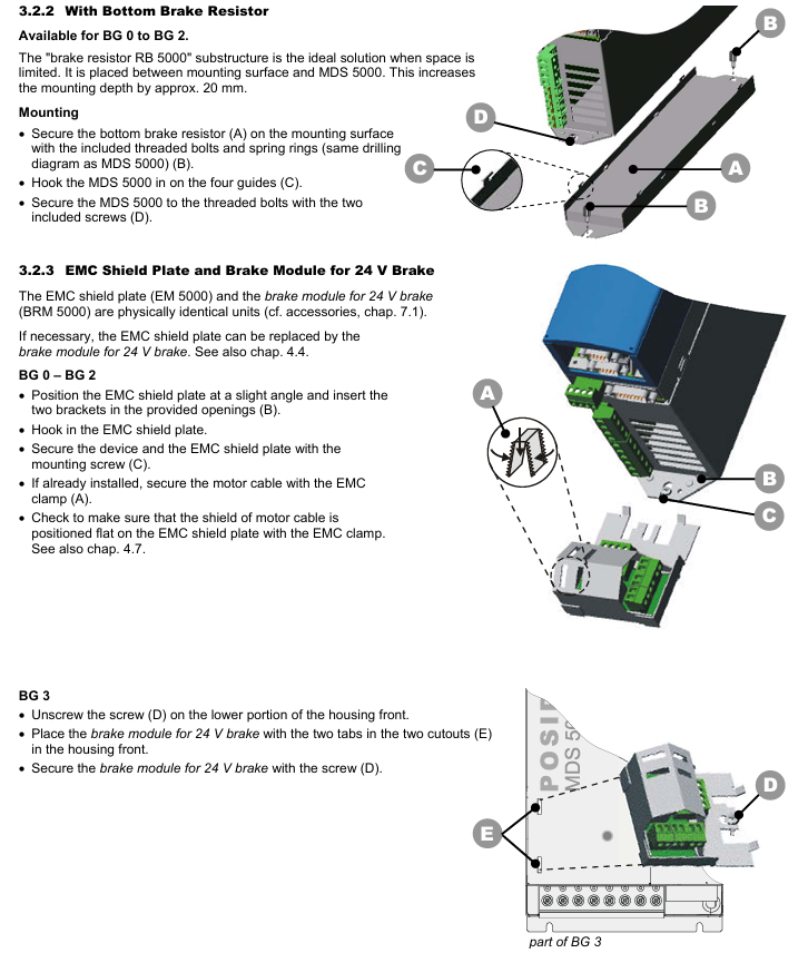
Accessory installation: Before installing the optional modules (fieldbus, I/O terminals), power off and discharge are required, and touching the gold-plated contacts is prohibited; The depth of the bottom braking resistor (RB 5000) is increased by about 20mm, and the EMC shielding board can be replaced with a 24V braking module.
(2) Electrical installation
EMC measures: Separate power lines from signal lines, use shielded wires for motor cables with a large area of shielding layer, and shield brake resistor cables exceeding 30cm.
Power and protection: Use RK1 level fuses (such as Bussmann KTS-R series), and choose 300/500mA or delayed RCD circuit breakers.
DC link coupling: Only three-phase equipment can be coupled, and parameter A38 (set 1 for group 2/3) needs to be set. In case of a fault, the entire power supply needs to be disconnected, and fuses need to be replaced in pairs.
Safe torque shutdown: achieved through the ASP 5001 option, requiring dual shutdown (enable+option), with at least one functional test per month.
Wiring and Connection
Key terminals: X1 (enable), X4 (encoder, no live plugging), X10 (power supply), X20 (motor), X22 (DC link), need to be wired according to pin definitions (such as X4 encoder compatible with EnDat) ®/ HTL/TTL/SSI)。
Example: The BRM 5000 module is used to connect the X300-X302230V brake with a 24V brake, and an interface relay needs to be added. The motor cable should be shielded if it exceeds 300mm.
accessories
(1) Accessories Overview
Accessory Name Part Number Description Remarks
Standard I/O terminal module (SEA 5001) 49576 2 analog inputs (11 bits+symbol), 2 analog outputs (± 10 bits), 5 binary inputs, 2 binary outputs Chapter 3.3.2 of this manual
Extended I/O Terminal Module (XEA 5001) 49015 3 analog inputs (1 15 bit+symbol, 2 11 bit+symbol resolution), 2 analog outputs (± 10 bits), 13 binary inputs, 10 binary outputs, 2 D-SUB 9: Incremental Encoder (TTL) or SSI Input/Output Interface (X20- compatible with SDS 4000) (2 D-SUB 9 with the same function, simplified signal transmission) Chapter 3.3.2 of this manual
X120 SSI connection cable 49482 is used to connect the X120 SSI interface to XEA 5001, Chapter 5.3
Rotary Transformer I/O Terminal Module (REA 5000) 44570 2 analog inputs (1 15 bit+symbol, 1 11 bit+symbol resolution), 2 analog outputs (± 10 bits), 5 binary inputs, 2 binary outputs, 1 D-SUB 9: Rotary Transformer Connection (16 bits), 1 D-SUB 9: Incremental Encoder Simulation (TTL) Chapter 3.3.2 of this manual
EMC shielding board (EM 5000) 44959 motor line shielding connection module, can be added to the basic shell in Chapters 2.2 and 3.2.3 of this manual
The 24V brake module (BRM 5000) 44571 is used to activate the 24V motor holding brake and is delivered together with the EMC shielding board. It can be added to the basic housing in chapters 3.2.3 and 4.4 of this manual
POSISwitch ® Connecting cable (0.5m) 45405-45386 POSISwitch ® To POSIDRIVE ® Connecting cable for AX 5000/MDS 5000 (0.5m, prefabricated)-
POSISwitch ® Connecting cable (2.5m) 44574 POSISwitch ® To POSIDRIVE ® Connection cable for AX 5000/MDS 5000 (2.5m, prefabricated) (DSP402 in preparation)
CANopen DS-301 fieldbus module (CAN5000) 44575 CAN bus coupling Chapter 3.3.1 of this manual, supplementary document: fieldbus/CANopen, document numbers 441684 (German), 441686 (English)
PROFIBUS DP-V1 fieldbus module (DP5000) 49014 PROFIBUS DP-V1 coupling Chapter 3.3.1 of this manual, supplementary document: Fieldbus/PROFIBUS, document numbers 441685 (German), 441687 (English)
EtherCAT Option Module (ECS5000) - Real time Ethernet Link EtherCAT, implemented through CANopen in Chapter 3.3.1 of this manual, supplementary document: Fieldbus/EtherCAT, document numbers 441895 (German), 441896 (English)
EtherCAT cable (0.21m) 49313 CAT5e Ethernet jumper, yellow Chapter 5.3
EtherCAT cable (0.38m) 49314 CAT5e Ethernet jumper, yellow Chapter 5.3
Startup Lock ASP 5001- Only available for installation by ST Ö BER ANTRIEBSTECHNIK, please select Chapter 4.6 at the time of ordering
The product CD "ST Ö BER ELECTRIC 5000" 44989 includes POSITool (PC program for inverter programming, operation, and monitoring), documentation, and fieldbus files that can be accessed from http://www.stoeber.de Download POSITool
G3 connection cable 41488, connecting cable between PC and MDS, with 9-pin sub D plug, socket/plug Chapter 5 (X3- Serial Interface)
USB to RS232 adapter 45616--
The external operator ControlBOX 42224 is an operation unit used for setting and operating inverter parameters, including a 1.5m connection line supported by SV 5.1 and above versions. The ControlBOX documents are numbered 441445 (German), 441479 (English), and 441651 (French); Extra cables: 5m (part number 43216), 10m (part number 43217)
96x96mm DIN housing with built-in external operator 42225 protection level IP54, other functions are the same as above-
(2) Braking resistor
1. FZM (U), FZZM, and VHPR series
Listed are the part numbers, thermal time constants, compatibility with various MDS 5000 models for different types of braking resistors (such as FZM 330x35 250W 300 Ω, FZMU 400x65 600W 100 Ω, etc.), as well as the size parameters (length, diameter, height, mounting hole size, etc.) and weight of the FZM (U)/FZZM (IP20 protection level) and VHPR (IP54 protection level) series.
2. FZT, FZZT, FZDT, and FGFT series
Includes part numbers, thermal time constants, compatibility with MDS 5000 (MDS 5220, MDS 5370, MDS 5450) for various models (such as FZT 400x65 600W 22 Ω, FZZT 400x65 1200W 20 Ω, etc.), as well as size parameters and weights for FZT/FZZT/FZDT and FGFT series.
3. Bottom brake resistor RB 5000
The part numbers, thermal time constants, compatibility with various MDS 5000 models (RB 5022 100W 22 Ω, RB 5047 60W 47 Ω, etc.), dimensional parameters (height x width x depth), drilling drawings (the same as MDS 5000), weight and power cord length, protection level IP54, refer to Chapter 2.2 Dimensional Drawings and Chapter 3.2.2 Mechanical Installation.
(3) Output derating device
1. Technical parameters
Safety warning: Using an output derater beyond the rated data (cable length, current, frequency, etc.) may cause overheating and fire, and should be operated within the rated data range; When the cable length exceeds 50m and ST Ö BER ANTRIEBSTECHNIK cable is not used, the fault assessment of the motor temperature sensor may be affected by the cable capacitance. The wire cores of the motor temperature sensor and the brake need to be separated (with a maximum length of 100m), otherwise it may cause the machine to stop.
|Model | MDB-G0 3x4-3000 (part number 49582) | MDB-G1 3x16-900 (part number 49583) | MDB-G2 3x32-500 (part number 49584)|
|Specifications | BG0 | BG1 | BG2|
|Voltage Range | 3 × 0-500V | Same Left | Same Left|
|Frequency range | 0-150Hz | Same left | Same left|
|Servo motor operation (servo control mode) -8kHz rated current | 3A | 10A | 20A|
|Servo motor operation (servo control mode) -8kHz maximum overload | 250%/2 seconds, 200%/5 seconds | Same left | Same left|
|Servo motor operation (servo control mode) - maximum motor voltage | 1.0kV | same left | same left|
|Servo motor operation (servo control mode) - maximum dU/dt | 3.5kV/μ sec | same left | same left|
|Three phase current motor operation (V/f, VC, SLVC control mode) -4kHz rated current | 4A | 16A | 32A|
|Three phase current motor operation (V/f, VC, SLVC control mode) -4kHz maximum overload | 180%/5s, 150%/30s | Same left | Same left|
|Three phase current motor operation (V/f, VC, SLVC control mode) - maximum motor voltage | 1.4kV | same left | same left|
|Three phase current motor operation (V/f, VC, SLVC control mode) - maximum dU/dt | 3.0kV/μ sec | same left | same left|
|Maximum allowable cable length | 100m | Same left | Same left|
|Output derating temperature | 45 ° C | Same left | Same left|
|Design | Open | Same Left | Same Left|
|Power consumption | 40W | 80W | -|
|Connection method | Screw terminal | Same left | Same left|
|Maximum output derating/mm ² | 4.0 | 6.0 | -|
|Certification | (in preparation) | Same left | Same left|
2. Dimensional parameters
Model L (mm) H (mm) B (mm) N1 (mm) N2 (mm) Ø D (mm) Threaded joint connection (mm ²) Weight [kg]
MDB-G0 3x4-3000 95 110 66 62.5 40 5.8 M5 4 2
MDB-G1 3x16-900 125 160 71 100 55 5 M4 4 3
MDB-G2 3x32-500 155 185 91 130 71 8 M7 16 6
- YOKOGAWA
- Reliance
- ADVANCED
- SEW
- ProSoft
- WATLOW
- Kongsberg
- FANUC
- VSD
- DCS
- PLC
- man-machine
- Covid-19
- Energy and Gender
- Energy Access
- Renewable Integration
- Energy Subsidies
- Energy and Water
- Net zero emission
- Energy Security
- Critical Minerals
- A-B
- petroleum
- Mine scale
- Sewage treatment
- cement
- architecture
- Industrial information
- New energy
- Automobile market
- electricity
- Construction site
- HIMA
- ABB
- Rockwell
- Schneider Modicon
- Siemens
- xYCOM
- Yaskawa
- Woodward
- BOSCH Rexroth
- MOOG
- General Electric
- American NI
- Rolls-Royce
- CTI
- Honeywell
- EMERSON
- MAN
- GE
- TRICONEX
- Control Wave
- ALSTOM
- AMAT
- STUDER
- KONGSBERG
- MOTOROLA
- DANAHER MOTION
- Bentley
- Galil
- EATON
- MOLEX
- Triconex
- DEIF
- B&W
- ZYGO
- Aerotech
- DANFOSS
- KOLLMORGEN
- Beijer
- Endress+Hauser
- schneider
- Foxboro
- KB
- REXROTH
- YAMAHA
- Johnson
- Westinghouse
- WAGO
- TOSHIBA
- TEKTRONIX
- BENDER
- BMCM
- SMC
- HITACHI
- HIRSCHMANN
- XP POWER
- Baldor
- Meggitt
- SHINKAWA
- Other Brands
- UniOP
- KUKA
- IBA
- Beckhoff
- ADLINK
-
ADLINK HPCI-14S12U - Industrial Control Backplane 12PCI Backplane PCI-14S Passive Backplane
-
ADLINK PCIe-GIE74C - image acquisition card 4-CH GigE Vision PoE+ Frame Grabber
-
ADLINK PCI-8164 - control card 4-Axis Advanced Motion Controller Board
-
ADLINK PCIe-U304 - 4 Port USB3 PCIe Frame Grabbers USB Screw Hole Card
-
ADLINK PCI-9112 - Multi-Function Data Acquisition Card DAQ Card
-
ADLINK PCI-7432 - 51-12013-0A50 4-CH Isolated Numérique I/O PCI Cartes Digital I/O Card
-
ADLINK PCA-6106P3-0C1 REV.C1 - backplane 6-Slot Passive Backplane Board
-
ADLINK PCI-7224 - 24-CH Opto-Isolated Digital I/O PCI Board
-
ADLINK CPCI-7433R(G) - Digital Input Board Rear I/O CompactPCI Card
-
ADLINK EBP-13E4 - 51-46703-0A30 Industrial PC Backplane Passive Backplane
-
ADLINK PCIE-HDV62 - Image acquisition card High Definition Video Frame Grabber
-
ADLINK EBP-13E4 - 51-46703-0A30 Industrial Backplane Board Passive Backplane
-
ADLINK 90111-B1 / CPCI-6770 - PCB CPU MODULE CompactPCI Single Board Computer
-
ADLINK PCI-7248 - DATA ACQUISITION PCI CARD 48-CH Parallel Digital I/O Board
-
ADLINK PCI-7230 - 51-12003-0a50 board PCI7230 32-CH Isolated Digital I/O Card
-
ADLINK PCI2A000CB - 51-20000-0B30 Multi-Function DAQ Card Baseboard
-
ADLINK PCI-8134-005 - 4-Axis Motion Controller Card
-
ADLINK PCI-7224 - 24-CH Opto-Isolated Digital I/O PCI Card
-
ADLINK PCI-7434 - 64-CH Isolated Digital Output Card
-
ADLINK PCI-8132 - motion control card 2-Axis Servo & Stepper Controller
-
ADLINK PCI-8134 - Motion Controller PCI Card 4-Axis Controller Board
-
ADLINK PCI-8164 - Motion Control Card 51-12406-0A40 4-Axis Controller
-
ADLINK 51-12001-0C20 - Circuit Board Data Acquisition Interface Module Hardware
-
ADLINK NuPR0-840 - industrial control motherboard Full-Size PICMG CPU Board
-
ADLINK PCI-7444 - 51-12023-0A10 card 128-CH Isolated Digital Output Board
-
ADLINK PCI-1612B - data acquisition card 4-Port RS-232/422/485 Serial Communication Card
-
ADLINK PCI-6208V 009 - 8/16-CH 16-Bit Analog Output Cards PCB-I-E-482=6BX3
-
ADLINK NUPRO-935A/LV - industrial control motherboard Full-Size PICMG SBC Board
-
ADLINK PCI-9114DG - Multi-Function DAQ Card Data Acquisition PCI Card
-
ADLINK ACL-7130 - Data acquisition card Isolated Digital I/O Board
-
ADLINK ABX-6300D-4E1-BP - board ABX6300D4E1BP Video Interface Expansion Card
-
ADLINK CPCI-6940 - CPCI-6940/D1539/M16-0(EA)-000E 6U CompactPCI Processor Board
-
ADLINK NuPRO-760 - industrial control motherboard Half-Size PICMG SBC CPU Board
-
ADLINK IMB-M42H (G)-0020 - industrial control motherboard LGA1155 Micro-ATX Mainboard
-
ADLINK RTV-24 / PCI-MP4S - 51-12519-1C30 4-Channel Real Time Video Capture Board
-
ADLINK PCI-8134 - 4-Axis Servo & Stepper Motion Controller Card
-
ADLINK MXC-6101D - V.PC000.002.ST.00 Box PC Configurable Embedded Computer
-
ADLINK PCI-8134A - 51-12421-0A10 Motion Control Card 4-Axis Controller Card
-
ADLINK DIN-100S / DIN-100SA1 - Technology SCSI-II TB 100-PIN Terminal Block Board
-
ADLINK DIN-812M001 / DIN812M001 - 51-14034-0A1 51140340A1 Terminal Module Breakout Interface
-
ADLINK PCI-8164 - Servo motion control 4-Axis Advanced Controller Card
-
ADLINK PCIe-GIE64 - Acquisition card GigE Vision PoE+ Frame Grabber
-
ADLINK M-302 - Industrial control motherboard ATX PC Board Mainboard
-
ADLINK PCI-8134 - Motion Controller PCI Card 4-Axis Controller Board
-
ADLINK PCI-RTV24 - Image capture card Analog Video Frame Grabber
-
ADLINK PCI-8102 - Motion control card 2-Axis Servo & Stepper Controller Board
-
ADLINK PCI-9112 REV.B1 - Card Multi-Function Data Acquisition Card
-
ADLINK HSI-DI32-M-N / HSL-TB32-M-DIN - Discrete I/O MODULE Distributed Automation Module System
-
ADLINK PCI-7296 - IO card REV.A3 96-CH Parallel Digital I/O Card
-
ADLINK DIN-814P-A4 / 814Y - terminal board Motion Control Interface Block
-
ADLINK DIN-814P-A4 - 51-14056-0A10 PCB-I-E-2736=ZA01 Screw Terminal Board Breakout
-
ADLINK M-322 - motherboard Industrial Control Computer Mainboard
-
ADLINK NUPRO-406 REV:B1 - industrial control motherboard Full-Size PICMG CPU Board
-
ADLINK AMP-204C - card DSP-Based 4-Axis Advanced Pulse-Train Controller
-
ADLINK HPCI14S REV.B1 - industrial computer baseboard 14-Slot Passive Backplane
-
ADLINK PCI-7250 - 8-CH Relay Output & 8-CH Isolated DI PCI Card
-
ADLINK EBP-13E2 - baseplate Passive Backplane Industrial Computer Chassis Board
-
ADLINK LPCI-3488A - PCI-GPIB card 51-12801-0A30 acquisition card IEEE-488 Interface Board
-
ADLINK PCI-6216V-GL - 51-12201-0C30 16-CH 16-Bit Voltage Analog Output Card
-
ADLINK ACL-8454 - 16-CH Isolated Digital I/O & 4-CH Counter Card
-
ADLINK HPCI-9S7U - backplane Passive Backplane Compatible with NuPRO-A301 852 841 842
-
ADLINK DAQ-2010-007 - Simultaneous-Sampling Multi-Function Data Acquisition Card
-
ADLINK MP-C154 - 51-64205-0A10 Motion Control Card 4-Axis Controller Board
-
ADLINK MXE-202/mSSD16B/WiFi-BT - Matrix Rugged I/O Platform Embedded Fanless Computer
-
ADLINK CM-920-R-17 - PC/104-Plus Single Board Computer Module Intel Celeron M
-
ADLINK PCI-7250 NSMP - 8-CH Relay Output & 8-CH Isolated DI Card
-
ADLINK PCI-8164 - 4-Axis Motion Controller PCI Card W/ Cable and Breakout Box
-
ADLINK EMX-100 - Ethernet-based 4-axis Motion Controllers Distributed Motion Module
-
ADLINK PCI-8134A - Press control card 4-Axis Motion Controller Board
-
ADLINK M-845EG REV:3.2 - industrial motherboard Pentium 4 Socket 478 Micro-ATX
-
ADLINK PCI-9114A Rev A2 DG - card High-Resolution Multi-Function Data Acquisition Board
-
ADLINK IEC-915GV - REV 1.1 Industrial motherboard Socket 478 CPU Board
-
ADLINK PCI-9111DG(G) - Data Acquisition Card Multi-Function DAQ Card
-
ADLINK HPCI-15S10 REV:B2 - Industrial computer base plate Passive Backplane Board
-
ADLINK NuPR0-840 / NuPR0-840DV - industrial control motherboard Full-size PICMG CPU Board
-
ADLINK RTV-24 / PCI-MP4S - 51-12519-1C30 4-Channel Real Time Video Capture Board
-
ADLINK NUPRO-780 - industrial control motherboard Pentium III Single Board Computer
-
ADLINK PCI-7296 - 0050 card 96-CH Opto-Isolated Parallel DIO Card Set
-
ADLINK NUPRO-780 - industrial control motherboard PICMG Full-Size SBC
-
ADLINK PCI-7248 - 51-12006-0A3 002 Pci 7248 48-CH Parallel Digital I/O Card
-
ADLINK PCI-7230 - 32-CH Isolated Digital I/O Card
-
ADLINK AMP-204C - motion control card 4-Axis Advanced Controller Board
-
ADLINK PCI-1714UL - Card Ultra High-Speed 4-CH Simultaneous Sampling DAQ
-
ADLINK NuPRO-E330 - industrial computer equipment motherboard PICMG 1.3 SHB SBC
-
ADLINK AMP-204C - DSP-Based 4-Axis Advanced Pulse-Train Motion Controller Module
-
ADLINK PCI-7256 - 001 51-12206-0A2 REV.A2 LPCI-7256 16-CH Latching Relay Output Card
-
ADLINK ND6050 - NUDAM DIGITAL I/0 MODULE Distributed I/O Unit
-
ASEM BM100 - Box PC Embedded Fanless Industrial Computer
-
ADLINK PCI-7250 - PCI Acquisition Card 8-CH Relay Output & Isolated DI Board
-
ADLINK PCI-8164 - Servo motion control 4-Axis Controller Card
-
ADLINK NuPRO-A40H - Industrial Motherboard 51-41807-1A30 OSP LGA1155 H61
-
ADLINK ADMAX X300 SERVER - 51066010-0A30 motherboard Multi-Processor Mainboard
-
ADLINK CMe-GIE62+ - 51-32903-0A30 control card PC/104-Plus GigE Vision Frame Grabber
-
ADLINK NUPRO-780 - industrial control motherboard Full-Size PICMG SBC CPU Board
-
ADLINK ETX-AT-N270-18/GKTEL - 51-71111-OB10 motherboard ETX CPU Module Board
-
ADLINK DIN-812M - interface module Terminal Block Connection Board
-
ADLINK IMB-M42H - industrial control motherboard LGA1155 Micro-ATX Mainboard
-
ADLINK PXIS-2508 - 8-slot 3U PXI Instrument Chassis Power Hardware Assembly
-
ADLINK AMP-208C - Motion Control card DSP-Based 8-Axis Pulse-Train Controller
-
ADLINK PCI-9111 / PCI-9111DG - Multi-Function Data Acquisition Card DAQ Board
-
ADLINK IEEE-488 GPIB card - Bus Interface Controller Communication Board
-
ADLINK RTV-24 - 51-12519-1C30 image acquisition card Video Frame Grabber Card
-
ADLINK TB-24P/24-01 - Board 24 Way Screw Terminal Breakout Board
-
ADLINK HSL-DI16DO16-DB-NN - 51-23015-0A40 Distributed Discrete I/O Module Set
-
ADLINK PCI-7442 - switch quantity card data acquisition card 64-CH Isolated Card
-
ADLINK ACL-7130 REV. B2 - industrial control capture card Isolated Digital I/O PCI Card
-
ADLINK PCI-6S / PCI6S - Backplane 6-Slot Passive Backplane Chassis Board
-
ADLINK ACL-8113A - card Isolated Digital Input Card
-
ADLINK CPCI-6208V-003 - board cPCI CompactPCI 8-CH Analog Output Card
-
ADLINK DIN-100S-01(G) - SCSI 100-Pin Terminal Block Interface Board
-
ADLINK PCI-7433 - Isolated Digital Input Card 64-CH
-
ADLINK PCI-9812 - Synchronous sampling analog input card High-Speed DAQ Board
-
ADLINK PCI-7434 REV.B1 - PLOTECH PCB-I-E-1182=6EX2 64-CH Isolated Digital Output Card
-
ADLINK PCIe-RTV24 - 51-18016-0A20 4-CH Real-Time Video Capture Card PCIe Frame Grabber
-
ADLINK PCI-8144 / PCI-8144N - Motion control card 4-Axis Stepper Motor Controller
-
ADLINK DIN-68S-01 - terminal board 68-Pin Connector Terminal Block
-
ADLINK MP-C154 - Motion control card 4-Axis Advanced Controller Card
-
ADLINK PCI-7248 (G) - Motherboard 48-CH Parallel Digital I/O Card
-
ADLINK MXE-1301(G) - Intel Atom D2550+NM10 MXE 1300 Series 93-4130-0030 Embedded Computer
-
ADLINK PRO-841 Rev 2.0 / PRO-060907000670 - CPU 2.26GHz & RAM Industrial PC Board
-
ADLINK cPCI-6626 - 6U CompactPCI 2.0 Blades i7-2710QE PCB-I-E-2570=9N41
-
ADLINK MXC-6322D(G) - Industrial Fanless Computer
-
ADLINK cPCI-8168-004 - CompactPci NulPC Motion Control Board 51-36402-0A3
-
ADLINK CPCI-7300[G] - COMPACTPCI Digital I/O Card Data Acquisition
-
ADLINK CPCI-6626/2710/M4G - COMPACTPCI COMPUTER BOARD
-
ADLINK cPCI-8168-009 - cPCI NulPC Motion Control Board
-
ADLINK cPCI-6626/2710/M4G - VME CPU Board Computer Board
-
ADLINK CPCI-R6200(G)-0040 - COMPACTPCI CONTROL BOARD

K-JIANG

Add: Jimei North Road, Jimei District, Xiamen, Fujian, China
Tell:+86-15305925923