

K-WANG


Siemens 7XV5653-0BA00 dual channel binary signal transmitter
Siemens 7XV5653-0BA00 dual channel binary signal transmitter
Overview
The operation manual for Siemens 7XV5653-0BA00 dual channel binary signal transmitter covers all aspects of the equipment from basic information to specific operations. It is suitable for technical personnel who have received professional training and have knowledge in the fields of instrumentation, control, and automatic control engineering, providing guidance for the safe installation, commissioning, operation, and maintenance of the equipment.
Basic Equipment Information
(1) Scope of application and compliance standards
Application scenario interference emission requirements Anti interference requirements
Industrial sector EN 50081-2: 1993 EN 50082-2: 1995
Residential sector (residential, commercial trade, small businesses) EN 50081-1:1992 EN 50082-1:1992
(2) Equipment functions and features
Core function: Dual channel bidirectional binary signal transmitter, capable of converting binary signals with a wide range of inputs. The signal status is serially sent to a similar remote converter through duplex optical fibers. The remote converter outputs the information as command contacts in real time, suitable for switch equipment. It can achieve interference free signal transmission through optical fibers, safely detect misoperations or transmission faults, and send signals through alarm relays.
Performance characteristics:
Two isolated binary inputs, with a wide input voltage range (18V-250VDC) and polarity reversal protection.
Two isolation command relays with large switch capacity.
Point to point connection with short operation time (12-118ms), depending on the data rate.
Fiber optic connection can achieve interference free transmission even in high electromagnetic interference environments.
Protocol communication has monitoring function and transmission security.
Long transmission distance, up to 3km under multimode fiber (62.5/125 μ m), and up to 100km under single-mode fiber when cascaded with 820/1300nm converter 7XV5461-0BA00.
Integrated wide range power supply unit with alarm contacts.
(3) Operation mode
Operation mode, working mode, alarm and signal transmission characteristics
Full duplex mode binary information can be transmitted in both directions simultaneously, such as for direction comparison or signal comparison (according to delivery status). In case of power failure, alarm relay M1 will be released; When no remote converter signal is received, the red LED (ERR) lights up and the alarm relay M1 is released; When running through a modem, if the data connection is interrupted for any reason, to avoid overloading the modem, the device will only send more data after 15 seconds, but will immediately transmit when the binary input signal changes
Half duplex mode binary information is only transmitted unidirectionally through fiber optic cables, requiring only one fiber optic transmitter from the input device to the output device (S2/DIP 7 is set to "transmit only"): in the event of a power failure, alarm relay M1 is released and the transmission link from the transmitter is not monitored;
Receiver (S2/DIP 7 set to "send/receive"): When there is a power failure, the alarm relay is released; When no transmitter signal is received, the fault indicator (red LED: ERR) stays on and the alarm relay M1 is released
(4) General Data and Data Transmission
Auxiliary power supply: Connect DC or AC auxiliary power supply through 2 terminals (N/L-L1/L -), with a wide range of auxiliary power supply (24-250V DC, 60-230V AC), without the need for internal jumper wires, and can be connected to all common substation batteries or AC mains voltage; There is a working voltage LED indicator light (green LED: RUN) on the front of the device, indicating whether the device is operating normally.
Data transmission: The optical interface adopts positive logic (light off in idle state), and the incident light is considered as a valid signal (=1, high level); Built in switch, compatible with negative logic system (fiber optic interface), factory set to positive logic (light off in idle state), and both converters must use the same logic. It is recommended to keep the factory settings.
Fiber optic connection: Fiber optic is connected to the converter through an ST connector.
RS232 interface connection: When connecting to the RS232 interface, it is necessary to disconnect the fiber optic transmission and set the communication to a serial interface; It can be connected to the serial interface of the converter through the serial 7XV5100-4 cable. If other cables are used, the 7th and 8th pins of the bridging cable need to be bridged, and the 1st and 4th pins (X1 of BST) are not assigned.
(5) Binary input
The two binary inputs (BI-1 and BI-2) have a wide input voltage range, with a logic high level "1" of 24V-250V DC (-15%,+20%) and a pickup threshold of 18V. In special cases (such as long-distance unshielded lines and high electrical interference), the threshold can be increased; The logic low level '0' is a voltage level below the threshold.
The corresponding yellow LEDs (BI-1, BI-2) light up when the corresponding binary input is activated (in a logic high state); The LED K1 and K2 display the status of the output contacts, which is set by the binary input in the serial telegram transmitted by the remote converter through fiber optic or RS232 connection (such as a modem with RS232 interface).
Application scenarios
(1) Application examples
With the help of this binary signal transmitter, two binary signals can be detected and transmitted directly to a distance of 3km through multimode cables and optical fibers, and output through relay contacts at remote stations; If single-mode fiber is used for transmission up to 100km away, it can be paired with repeater 7XV5461.
After connecting the device to the RS232 interface, it can also be transmitted through a modem or PCM device.
(2) Binary signal transmission through leased lines
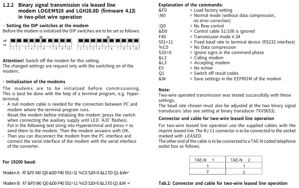
1. Dual line operation using LOGEM928 and LGH28.8D modems (firmware 4.13)
DIP switch settings for modems: Before setting, the modem needs to be turned off. After setting is complete, the modem needs to be turned on for the new settings to take effect.
Modem initialization: Before debugging, the modem needs to be initialized, preferably with the help of a terminal program (such as Hyperterminal); Use a zero modem cable to connect the PC and modem running the terminal program, reset the modem before initialization (press the switch when connecting the auxiliary power supply until the LED "A/O" flashes); Enter a specific text string in the super terminal and send it. The modem will reply with "OK", and then you can disconnect the modem from the PC interface and connect its serial interface to the converter's serial interface.
The string corresponding to 19200 baud rate:
Modem A:AT &V NO Q0 &D0 F40 S51=11 %C0 S20=0 &L2 E0 Q1 &W
Modem B:AT &F0 N0 Q0 &D0 F40 S51=11 %C0 S20=0 &L3 E0 Q1 &W
Command Explanation:
|Command | Meaning|
|&F0 | Load factory settings|
|N0 | Normal mode (no data compression, no error correction)|
|Q0 | No traffic control|
|&D0 | Ignore control cable S1/108|
|F40 | Transmission mode V.34|
|S51=11 | Fixed baud rate of terminal device (RS232 interface)|
|%C0 | No data compression|
|S20=0 | Ignore symbols in the command phase|
|&L2 | Calling modem|
|&L3 | Called modem|
|E0 | No echo display|
|Q1 | Close result code|
|&W | Save the settings to the EEPROM of the modem|
Connectors and cables for dual line leased line operation: Use the accompanying cable labeled "leased line" to connect the RJ-11 connector to the socket labeled "LEASED", and connect the other end of the cable to the TAE-N encoded telephone outlet box in a specific manner (TAE-N 1 # 1 to TAE-N 2 # 1, TAE-N 1 # 2 to TAE-N 2 # 2).
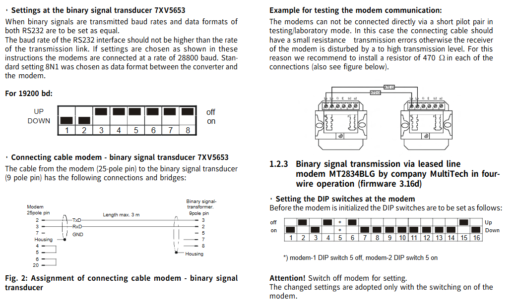
Setting of binary signal transmitter 7XV5653: When transmitting binary signals, the baud rate and data format of the two RS232 should be set to be the same; The baud rate of the RS232 interface should not be higher than the speed of the transmission link. When setting according to the instructions, the modem should be connected at a 28800 baud rate, and the data format between the converter and the modem should be set to 8N1 as the standard. The 19200 baud rate corresponds to specific DIP switch settings (DOWN/UP, off/on status).
The connection cable for modem binary signal transmitter 7XV5653: The cable from the modem (25 pin) to the binary signal transmitter (9-pin) has specific connection and bridging methods, with a maximum length of 3m.
Example of modem communication test: In test/laboratory mode, the modem cannot be directly connected through a short guide wire, otherwise excessive transmission levels will interfere with the modem's receiver. It is recommended to install a 470 Ω resistor in each connection.
2. Four wire operation using MultiTech's MT2834BLG modem (firmware 3.16d)
DIP switch settings for modem: Before setting, the modem needs to be turned off. After setting is complete, the modem needs to be turned on for the new settings to take effect. DIP switch 5 for modem 1 is set to off, DIP switch 5 for modem 2 is set to on, and other switches have specific off/on states (up/down direction).
Modem initialization: Before debugging, the modem needs to be initialized, preferably with the help of a terminal program (such as Hyperterminal); Use a zero modem cable to connect the PC and modem, input specific data (AT&FE0 # F0 $SB19200MB19200&E14&E3&W0) into the super terminal and send it, and the modem will reply with "OK".
Command Explanation:
|Command | Meaning|
|If the connection is correct, the modem replies with "OK"|
|&F | Load factory settings|
|E0 | No echo display|
|#F0 | Fixed baud rate of terminal device (RS232 interface)|
|Stable performance speed MB19200 | Fixed baud rate between modem 1 and modem 2|
|&E14 | Disable data compression|
|&E3 | Turn off traffic control|
|&W0 | Save Settings|
Connectors and cables for four line leased line operation: Use the accompanying cable labeled "leased line" to connect the RJ-11 connector to the socket labeled "LEASED", and connect the other end of the cable to the TAE-N encoded telephone outlet box in a specific way (with specific correspondence between TAE-N 1 and TAE-N 2 pins).
Technical parameters
Parameter Category Specific Parameters
Mechanical Design - Shell: Plastic EG90
-Size: See size chart
-Weight: Approximately 250g
-Protection level (according to EN60529): enclosure IP20, terminal IP20
-Protection level: Level II
Power consumption - DC voltage (UH=UHN, typical value): 3W
-AC voltage (UH=UHN, typical value): 3.5VA
Internal fuse cannot be replaced, 1.25AT
Status display: 1 green working LED (RUN)
RS232 connection - Connection method: 9-pin sub-D socket
-Maximum baud rate: 115200 baud
-Minimum baud rate: 1200 baud
Optical interface - optical input/output: 1 transmitter, 1 receiver, factory state: light off when idle; Transmitter ST: HFBR 1404; Receiver ST: HFBR 2402
-Optical connection: ST (plastic protective cover)
-Data display: None
-Wavelength: 820nm
-Transmission power: 50/125 μ m multimode fiber: -19dBm; 200 μ m HCS fiber: -6.2dBm
-Sensitivity: -30dBm
-Light budget: 10dB (+3dB system budget)
-Maximum transmission distance: 625/125 μ m fiber optic 3km
-Maximum baud rate: 115200 baud (recommended for fiber optic connections); Approximately 2.5mA at 1200 baud
2 binary inputs - Connection method: 2-pole connector Phoenix, isolated
-Switching voltage: 24-250V DC (-15%,+20%)
-Power consumption (voltage independent): approximately 2.5mA
-Status display: 1 yellow LED per input (BI-1, BI-2)
2 instruction outputs (relays) - Relay type: MSR relay (K1, K2), 1 floating normally open relay
-Connection method: 2-pole terminal Phoenix
-Switching voltage (rated voltage): 250V AC/DC
-Switch capacity: 5A (long-term); 30A (0.5s, if the relay displays); 50-270W (depending on voltage), each 1000VA
-Switching current: Long term 1A
-Status display: 1 yellow LED (K1, K2)
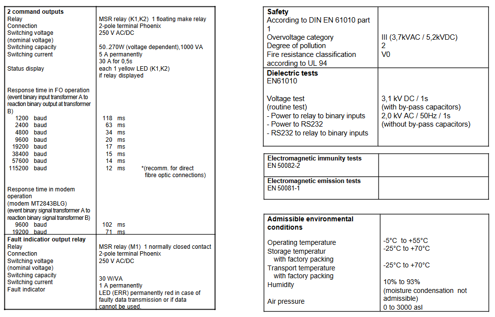
-Fiber optic operation response time (from binary input event of transmitter A to binary output response of transmitter B): 1200 baud 118ms, 2400 baud 63ms, 4800 baud 34ms, 9600 baud 20ms, 19200 baud 17ms, 38400 baud 15ms, 57600 baud 14ms, 115200 baud 12ms (recommended for direct fiber optic connection)
-Response time for modem operation (MT2843BLG modem) (binary signal event from transmitter A to binary signal response from transmitter B): 9600 baud 102ms, 19200 baud 71ms
1 fault indicator output relay - connection method: 2-pole terminal Phoenix
-Switching voltage (rated voltage): 250V AC/DC
-Switch capacity: 30W/VA
-Switching current: Long term 1A
-Fault indicator: No specific parameters
Safety (according to DIN EN 61010 Part 1) - Overvoltage category: Class III (3.7kVAC/5.2kVDC)
-Pollution level: Level 2
-Fire rating (according to UL 94): V0 level
Dielectric Loss Test (EN61010) - Power to Relay to Binary Input: 3.1kV DC/1s (with bypass capacitor)
-Power supply to RS232: 2.0kV AC/50Hz/1s (without bypass capacitor)
-RS232 to relay to binary input: 2.0kV AC/50Hz/1s (without bypass capacitor)
Electromagnetic compatibility test - Electromagnetic immunity test: EN 50082-2
-Electromagnetic emission test: EN 50081-1
Permissible environmental conditions - Operating temperature: -5 ° C to+55 ° C
-Storage temperature with factory packaging: -25 ° C to+70 ° C
-Transportation temperature with factory packaging: -25 ° C to+70 ° C
-Humidity: 10% -93% (no condensation allowed)
-Air pressure: 0-3000 ASL
Functional Unit Description
(1) Overall structure
The signal converter inside the casing is a hard wired and functionally tested unit, equipped with snap on mounting components for DIN EN 50022 35mm top cap rails; The auxiliary power supply can be safely connected through screw terminals; Fiber channel is adapted through ST terminals; The RS232 interface is connected through a 9-pin sub-D socket; The device does not contain silicone and halogens, and has flame retardancy.
(2) Terminal position and allocation
The terminal positions have a specific layout (see Figure 3), and each pin has a clear meaning and abbreviation, as follows:
|Pin | Meaning | Abbreviation|
|L+| Power supply L+| AC: L1; DC:L+|
|L - | Power supply L - | AC: N; DC:L-|
|Pin 1 | Fault signal relay contact M1 | 1 (normally closed contact)|
|Pin 2 | Fault signal relay contact M1 | 2 (normally closed contact)|
|Pin 3 | Command relay K1 | 3 (normally open contact)|
|Pin 4 | Command relay K1 | 4 (normally open contact)|
|5- Pin | Binary Input 1- | BI-1-|
|6+pins | Binary input 1+| BI-1+|
|7- Pin | Binary Input 2- | BI-2-|
|8+pins | Binary input 2+| BI-2+|
|Pin 9 | Command relay K2 | 9 (normally open contact)|
|Pin 10 | Command relay K2 | 10 (normally open contact)|
(3) Switch position and RS232 interface
DIP switch operation: DIP switches can be operated from the outside and have specific position layouts (see Figure 4).
RS232 interface (9-pin sub-D socket): Each pin has a clear description, abbreviation, and direction as DTE, as follows:
|Pin | Description | Abbreviation | Direction as DTE|
| ---- | ---- | ---- | ---- |
|1 | None | None | No connection|
|2 | Receive data | RxD | Input (←)|
|3 | Send Data | TxD | Output (→)|
|4 | None | None | No connection|
|5 | Signal Ground | GND|-|
|6 | None | None|-|
|7 | Signal Ground | GND|-|
|8 | Activity Interface Selection | Bridge | Input|
|9 | None | None|-|
Interface selection instructions:
|Connection status | Interface status | Remarks|
|Not connected | Fiber optic connection activated | Pin 8 open circuit, factory set to fiber optic connection|
|Bridge | RS232 connection activation | Bridge pins 8-7 at the input of the converter|
DIP switch (S1, S2) function:
S1 (2-position DIP switch):
|Switch | Position | Meaning|
|1 | Open circuit (off) | The light goes out when the fiber optic receiver is idle|
|1 | Closed (on) | The light is on when the fiber optic receiver is idle|
|2 | Open circuit (off) | The light goes out when the fiber optic transmission is idle|
|2 | Close (on) | The light is on when the fiber optic transmission is idle|
S2 (8-bit DIP switch): By combining different DIP switches (DIP1-DIP8), multiple functional settings can be achieved, including baud rate (1200-112200 baud), data format (8E1: 8-bit data, even parity, 1-bit stop bit); 8N1: 8-bit data, no checksum, 1-bit stop bit), MA function (block MA, enable MA), test mode (test mode on, test mode off), working mode (only transmit, send/receive), boot loader (boot loader on, boot loader off), specific combinations are shown in Table 7, bold indicates factory settings.
Special mode explanation:
Test mode enabled: The binary signal transmitter performs self-test. If the binary input is activated (voltage applied), the binary LED (BI-1 or BI-2) lights up, and the corresponding relay (K1 or K2) and associated LED (K1 or K2) are activated; The memory test diagnosis and DIP switch position will be output to the serial interface (RS232), which can be displayed through the terminal program running on the PC.
Test mode off: The binary signal transmitter is ready to operate normally.
Blocking MA: Blocking message output, not controlling relay.
Enable MA: Normal operation, message output is not blocked.
Only transmitting: Binary signal transmitters only function as transmitters and do not report missing incoming signals as communication errors.
Baud rate setting: query the baud rate once after power on (DIP switch position); In the activated test mode, the baud rate will be continuously queried and reset; Set baud rate during operation: Set the baud rate through DIP switch 0-2 and briefly switch the on/off state of DIP switch 6 (test mode).
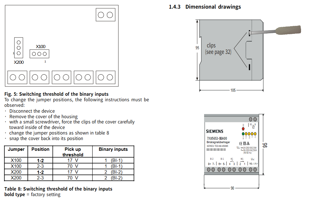
(4) Adjustment of picking threshold for binary input
To adjust the threshold of binary input, the binary signal transmitter needs to be turned on and the jumper changed. When the device is turned on, it is prohibited to run and the power supply needs to be disconnected first.
Steps for adjusting jumper position: Disconnect the power supply of the device → Remove the housing cover (carefully push the buckle of the cover towards the inside of the device with a small screwdriver) → Change the jumper position according to Table 8 → Clip the cover back to its original position.
Corresponding relationship between jumper position and picking threshold:
|Jumper | Position | Pick threshold | Binary input|
|X100|1-2|17V|1(BI-1)|
|X100|2-3|70V|1(BI-1)|
|X200|1-2|17V|2(BI-2)|
|X200|2-3|70V|2(BI-2)|
(5) Dimensional drawing
The equipment has specific size specifications, as shown on page 32 of the document, including the size parameters of components such as clips and terminals (such as 95mm, 105mm, 90mm, etc.).
Order data
Name, Model, Specification
Dual channel binary signal transmitter 7XV5653-0BA00 with 2 binary inputs, 2 command inputs, and 1 fault signal output (via terminals)
Installation and Debugging
(1) Installation precautions and steps
Installation warning: Some components of electrical equipment carry dangerous voltage during operation. Ignoring the operating instructions may result in serious personal injury or property damage. The installation and electrical connection of the equipment are only allowed to be carried out by qualified personnel, and all warnings must be strictly followed; Do not directly stare at the fiber optic transmission diode while wearing optical assistive devices; Prohibit operation when the device is turned on.
Installation requirements:
The installation location should be free of vibration and comply with the allowed ambient temperature (working or functional temperature, see technical parameters). Ignoring the temperature range required for normal function may lead to equipment failure and signal converter failure.
The equipment has a plastic casing and belongs to overvoltage category III according to DIN EN 61010 Part 1.
The signal transmitter can be installed on a 35mm top cap guide rail (according to DIN EN 50022) with a snap fit.
The equipment is only allowed to operate within a closed enclosure or cabinet, and the installation location is only accessible to qualified personnel.
Installation steps: Clip the binary signal transmitter onto the top cap guide rail using a snap on mounting component.
(2) Connection requirements and steps
Connection specifications: Electrical connections must comply with the installation regulations for high current devices, as well as VDE0100 and VDE0160 standards.
Power connection: The auxiliary power supply of the equipment needs to be equipped with an external isolation switch (for power safety isolation) and a safety device (fuse, 2AT or 4AT). The external isolation switch should be labeled accordingly, and the safety circuit breaker can simultaneously perform both functions.
Cable requirements:
Cable cross-section (single core cable or multi stranded wire): 0.5mm ² -2.5mm ².
Suggested stripping length: 5mm.
Multi strand wire connections require the use of insulated wire end sleeves (to avoid wire unraveling).
Fiber optic connection: only use fiber optic cables prepared according to regulations; Refer to the technical specifications for the type of optical fiber; Must comply with the allowed light budget (see technical specifications); When installing optical fibers, it is necessary to follow the prescribed bending radius.
Connection steps:
Connect the auxiliary power supply to terminals UH (DC: L+/AC: L1) and (DC: L -/AC: N).
Connect the fiber optic cable to the fiber optic receiver and transmitter through ST type terminals, or connect an RS232 cable.
(3) Debugging steps and requirements
Check if the operating data matches the values on the nameplate and do not make any changes to the equipment.
After completing the installation and connection, connect the auxiliary power supply, and the binary signal transmitter can be put into use. The green LED "RUN" will light up.
Setting up and maintenance
(1) Equipment settings
All settings of the binary signal transmitter (except for the pickup voltage of the binary input) can be made through an external DIP switch without opening the casing; The picking voltage setting for binary input requires opening the casing (see section 1.4.2); Specific setup instructions can be found in section 1.2.2 (setup of binary signal transmitter 7XV5653).
(2) Equipment maintenance
Binary signal transmitters do not require maintenance, and do not use any liquid reagents or substances during cleaning.
- YOKOGAWA
- Reliance
- ADVANCED
- SEW
- ProSoft
- WATLOW
- Kongsberg
- FANUC
- VSD
- DCS
- PLC
- man-machine
- Covid-19
- Energy and Gender
- Energy Access
- Renewable Integration
- Energy Subsidies
- Energy and Water
- Net zero emission
- Energy Security
- Critical Minerals
- A-B
- petroleum
- Mine scale
- Sewage treatment
- cement
- architecture
- Industrial information
- New energy
- Automobile market
- electricity
- Construction site
- HIMA
- ABB
- Rockwell
- Schneider Modicon
- Siemens
- xYCOM
- Yaskawa
- Woodward
- BOSCH Rexroth
- MOOG
- General Electric
- American NI
- Rolls-Royce
- CTI
- Honeywell
- EMERSON
- MAN
- GE
- TRICONEX
- Control Wave
- ALSTOM
- AMAT
- STUDER
- KONGSBERG
- MOTOROLA
- DANAHER MOTION
- Bentley
- Galil
- EATON
- MOLEX
- Triconex
- DEIF
- B&W
- ZYGO
- Aerotech
- DANFOSS
- KOLLMORGEN
- Beijer
- Endress+Hauser
- schneider
- Foxboro
- KB
- REXROTH
- YAMAHA
- Johnson
- Westinghouse
- WAGO
- TOSHIBA
- TEKTRONIX
- BENDER
- BMCM
- SMC
- HITACHI
- HIRSCHMANN
- XP POWER
- Baldor
- Meggitt
- SHINKAWA
- Other Brands
- UniOP
- KUKA
- IBA
- Beckhoff
- ADLINK
-
FANUC A06B-0169-B088 - AC Servo Motor Alpha M40 3000 3 KW
-
ALPHA WIRE 1299C-SLATE-1000 - Multi-Conductor Cable Wire
-
alpha / Wittenstein SK+180S-MF1-10-1M1-1K - Hypoid Gearbox i=10
-
ALPHA WIRE 1181/40C SL005 - Multi-Conductor Cable Wire
-
Generic / DSI Straight Anatomic Plastic Adapter Head + Screw Hex - Dental Implant Fixture
-
Alpha II-650 MV6500526A - Power Supply Unit
-
ALPHA WIRE 7036 WH001 - Hook-Up Wire
-
FANUC RDCGM00000004O / TP 050-MF1-7-061-000 - Gear Reducer / Alpha Gearbox
-
Alpha II-650 MV6500436A - TDK-Lambda Power Supply Unit
-
Alpha S-Alpha600 J60033 - 600W Switching Power Supply Unit
-
Alpha 1500W J00032 - Power Supply Unit
-
Alpha 600W H60638 - Switching Power Supply Unit
-
Alpha 650 MV6500314A - Power Supply Unit
-
Aloka UST-5413 - Linear Probe for Prosound Alpha 6
-
ALPHA WIRE TFT25015 NA002 - High Temperature Heat Shrink Tubing Wire Sleeving
-
JAVAD ALPHA2 / GrAnt-G3 - GPS Receiver
-
Alpha 400W H47318 - Switching Power Supply Unit
-
Alpha SG-ALPHA-202-001 / Q1001-010-001 - Circuit Board Module
-
Antlia Dual ERF H-Alpha & Cak/CaH - Density Astronomical Accessory
-
ALPHA WIRE 5100C SL033 - Multi-Conductor Cable Wire
-
ALPHA WIRE 5098C-SL033 - Multi-Conductor Cable Wire
-
Fanuc A06B-6290-H105 - Alpha Sv 80hv-B Module Servo Amplifier
-
FANUC A06B-6240-H105 - Aux Axis Alpha aiSV 80 Servo Amplifier
-
Endress+Hauser Alpha-Log RSA10-61B1S / 42974737/0130 - Data Logger Measurement Instrument
-
ALPHA WIRE 6363-SL002 - Multi-Conductor Cable Wire
-
Alpha SP100S-MF1-7-1K1-2S - Gear Reducer
-
Alpha SP 100G-MF1-4-0H1-2S-PGG - Planetary Gear Reducer
-
FANUC A06B-0143-B175 #0275 - Alpha 12/3000 AC Servo Motor
-
James Burn Alpha Doc P33 / GBC PDI - Automatic Punch DocuPunch
-
Titus HVAC 105383-01 - ALPHA BAC Controller and Actuator
-
Wittenstein Alpha SP 100S-MF2-20-0E0-2S - Planetary Gearbox i=20
-
Kashiyama Alpha-85-ZV / SP-8026G - Pump Controller
-
Christ Alpha 2-4 LDplus - Freeze Drier Part N/ 101542
-
Lambda / Alpha H40896 - 400W Power Supply Unit
-
Wittenstein Alpha LP-070S-MF1-3-1E1-38 - Planetary Gearbox
-
Matrox / EXO-2480 133-D06-3 / 398-17962-1 - Alpha Numeric PCB Board
-
Fanuc A06B-6096-H204 - Dual Axis Alpha Servo Amplifier Module
-
Alpha Wire 5002C-SL001 - Multi-Conductor Cable 2 Conductors 22AWG 300VAC
-
Alpha 600W H60638 - Switching Power Supply Unit
-
Alpha Scientific Spin Precession Dual Electro Magnet Beam Line Chamber - Electro Magnet Beam Line Chamber
-
ALPHA WIRE 6017C SL005 - Multi-Conductor Cable Wire
-
ALPHA WIRE 65804 SL002 - Multi-Conductor Cable Wire
-
Fanuc A06B-0152-B010 - AC Servo Motor Alpha A30/2000 with Brake
-
ALPHA WIRE 5856-VI001 - Hook-Up Wire
-
ALPHA WIRE M13142-SL001 - Multi-Conductor Cable Wire
-
Alpha & Omega AOZ1017 - 8-Pin SOIC SMD Buck Switching Regulator IC
-
Alpha 600W H67027 CA600 - 600W Switching Power Supply Unit
-
ALPHA WIRE 2845/7-RD001 - Hook-Up Wire
-
Wittenstein Alpha VH+063S-MF1-10-6H1-1K-0C2 - Worm Gear Reducer i=10
-
ALPHA WIRE 2414C SL022 - Multi-Conductor Cable Wire
-
ALPHA WIRE 5672-SL005 - Multi-Conductor Cable Wire
-
BECKHOFF / Alpha AM8021-0B10-0000 + CP 040-MO1-10 - Servo Motor with Planetary Gearbox
-
ALPHA Systems Lab Inc MBA-WV1-F / PCB-WV1-F - PCB Board
-
FANUC A06B-0826-B201 - Alpha P12 AC Spindle Motor
-
WF & HC / Alpha-E 10045 - Tiller Bar Flat Flange Inlet 3150LB 3X 2.5 Inch
-
Seiler Alpha Air 3 - Dental Microscope
-
Alpha 400W H47223 - Switching Power Supply Unit
-
Wittenstein Alpha SP 180S-MC1-5-1M0-2K - Planetary Gearbox
-
FANUC A06B-6117-H211 - Servo Amplifier Module Alpha iSV 160/160 Amp
-
Alpha S-Alpha600 J60033 - 600W Switching Power Supply Unit
-
Adaptive Alpha Eclipse StreetSmart Model 17X - Master Slave LED Sign 44 x 44 Inch
-
ALPHA WIRE 391697-WH005 / 391697WH005 - Hook-Up Wire
-
Generic 22W Laser Engraver Cutter - Smart Air Pump APP Control CNC Dual-core CPU DIY Tools
-
FANUC A06B-6102-H226 / A06B6102H226 - Spindle Amplifier Module
-
FANUC A06B-6090-H006 / A06B6090H006 - Servo Power Supply Module
-
Alpha Wire Apr-19 - High Low Temperature Cable 75 FT
-
Wittenstein Alpha HG+ 075S-MF2-28-6E1-1S10 - Hypoid Gearbox Reducer i=28
-
Alpha J00032 - 1500W Power Supply Unit
-
Alpha H47038 - 400W Power Supply Unit
-
FANUC A06B-6096-H204 - Dual Axis Alpha Servo Amplifier Module
-
Wittenstein Alpha LPB090-MO1-10-111-00 - Alpha Planetary Gearbox
-
ALPHA WIRE 2842/19-YL001 - Hook-Up Wire
-
WITTENSTEIN ALPHA HG+060S-MF1-56C1-1K00 - Planetary Gearbox
-
Basler A102K Alpha VIS - Black and White CCD Industrial Camera
-
Alpha H40935 - 400W Power Supply Unit
-
FANUC A06B-6114-H207 - 2-Axis Servo Amplifier Module SVM20/40i Alpha i Series
-
TDK-Lambda / Alpha H47318 - 400W Switching Power Supply Unit
-
HITACHI Aloka Prosound Alpha 7 Premier - Diagnostic Ultrasound System
-
Alpha SP100S-MF1-4-1E1-2S - Precision Gear Reducer
-
FANUC A20B-2001-0950 - Control Circuit Board PCB
-
ALPHA WIRE 2855/1-GR001 - Hook-Up Wire
-
FANUC A06B-6096-H204 - Dual Axis Alpha Servo Amplifier Module
-
Wittenstein Alpha LPB090-MO1-10-111-00 - Alpha Planetary Gearbox
-
ALPHA WIRE 2842/19-YL001 - Hook-Up Wire
-
Basler A102K Alpha VIS - Black and White CCD Industrial Camera
-
Wittenstein Alpha LP 090-M01-7-111-000 / Schneider - Gear Box i:7 Schneider Electric Servo Motor
-
LAMBDA ALPHA 600W H60554 - Switching Power Supply Unit
-
Fanuc A06B-0238-B100 / A860-2000-T301 - AC Servo Motor with Encoder
-
FANUC A06B-6290-H322 - ALPHA iSV 10/10/10HV-B 3-Axis Servo Drive
-
Polymotor Italiana 9919 121 90332 / Alpha SP75-M1-3 - D.C. Permanent Magnet Motor with Gearbox
-
MJ Research PTC-200 - PCR DNA Engine Thermal Cycler with Dual 48-Well Alpha Block
-
ALPHA WIRE 5002C-SL002 - Multi-Conductor Cable Wire
-
Fluke / Victoreen ASM 990 / 489-110D - Biomedical Radiation Detector Probe with Pelican Case
-
ALPHA WIRE 5855-BK001 - Hook-Up Wire 22AWG Silver Plated Copper
-
Tetra / Alpha 600W H60552 - Switching Power Supply Unit
-
Bruker Alpha FTIR Spectrometer / Alpha-P ATR - Infrared Spectrometer FTIR Instrument
-
Simagic AlphaM-FX-C 290mm FX-C - Formula Steering Wheel with Alpha Mini Wheel Base
-
Alpha Wire 5152C 20/2C - XtraGuard High Performance Instrumentation/Control Cable
-
ALPHA WIRE 1219/40C SL005 - Multi-Conductor Cable Wire
-
ALPHA WIRE 3131441 TN005 - Multi-Conductor Cable Wire
-
ALPHA WIRE 2172-SV005 - Multi-Conductor Cable Wire
-
FANUC A20B-2100-0742 - ALPHA ia Servo Control Board
-
Olympus Endo Alpha Cart TI-A1 - Medical Equipment Cart with Accessories
-
ALPHA WIRE 74010-BK002 - Multi-Conductor Cable Wire
-
Fanuc A06B-6110-H026#N - ALPHA i Power Supply Module PSM-26i
-
Alpha Laval SX2/013 - Rotary Lobe Pump
-
Alpha II-450P MV4500007B - Switching Power Supply Unit
-
TDK-Lambda / Alpha 400W - Switching Power Supply Unit
-
ALPHA ALPHA6000E-3015GB/3018PB - Frequency Inverter Drive Power Converter
-
ALPHA WIRE 391245-WH005 - Hook-Up Wire
-
Alpha H60562 CA600 - 600W Switching Power Supply Unit
-
Fanuc A06B-0147-B675 - Alpha 22/2000 3.8kW 2000rpm AC Servo Motor
-
ALPHA WIRE 9821 - Twinaxial Cable 1PR 25AWG Poly Insulation
-
Fanuc / Alpha A16B-2203-0820 - ALPHA i Spindle Wiring PCB
-
FANUC A20B-2100-0742 - ALPHA ia Servo Control Board
-
Fanuc A06B-6096-H104 - Alpha Servo Module
-
Fuji Electric RYT202D5-VV2 / Faldic Alpha5 - Servo Amplifier
-
ALPHA WIRE 2817/6 20 AWG - PTFE High Temperature Cable
-
Aloka Prosound Alpha 10 / EU-6031C / JB-274D - High Voltage Power Supply for Ultrasound
-
Wittenstein Alpha SP 140S-MF1-5-01F-2S - Planetary Gearbox
-
FANUC A06B-6124-H205 - Alpha iSV Servo Amplifier Module
-
TDK-Lambda / Alpha MV6500314A - 650W Power Supply Unit
-
TDK-Lambda / Alpha H47318 - 400W Switching Power Supply Unit
-
Alpha H47318 - 400W Switching Power Supply Unit
-
CNC Bearing / Alpha AR090-S1-300-20-N - Robotics Bearing Component
-
Alpha CA400 5A,3.3Q,5B,12/12E / DXH47037 - 400W Power Supply Unit
-
FANUC A20B-2100-0742 - ALPHA ia Servo Control Board
-
Fanuc / Amada A04B-0810-C403 / LC1212 alpha II - Pressure Regulator

K-JIANG

Add: Jimei North Road, Jimei District, Xiamen, Fujian, China
Tell:+86-15305925923