
K-WANG


YASKAWA MEMOCON-SC 2000 series reversible counter module
YASKAWA MEMOCON-SC 2000 series reversible counter module
Core positioning
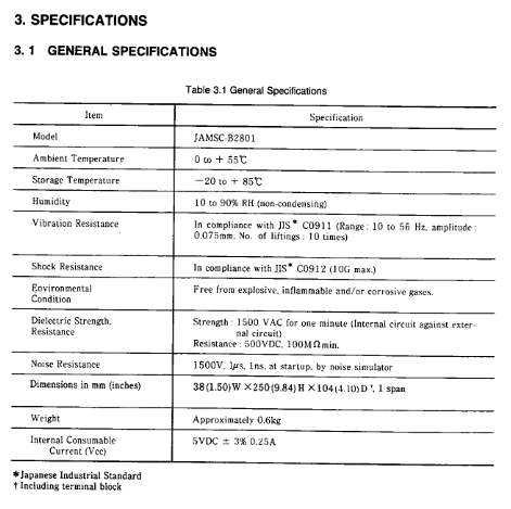
Applicable product: Reversible counter module B2801 (model JAMSC-B2801)
Core application: Pulse counting, signal comparison, data sampling and storage in industrial scenarios, outputting external coincidence signals
Compatible devices: MEMOCON-SC series CPU modules (GL20, GL60S)
Core specification parameters
Specific description of category key parameters
Environmental specifications Operating temperature 0-55 ℃ (Storage temperature -20-85 ℃)
Humidity 10-90% RH (non condensing)
Anti vibration/anti impact in accordance with JIS C0911/C0912 standards
Performance specification count bit GL20: 6 bits (0-999999); GL60S: 8-bit (0-99999999)
Counting speed X1 mode 50kpps, X2 mode 100kpps, X4 mode 200kpps
Two independent counter circuits with two counter channels
Input voltage supports 5V, 12V, 24V pulse input
Output capability: open collector output, maximum load 29V/250mA
Physical dimensions (mm) 38 (width) × 250 (height) × 104 (depth)
Weight approximately 0.6kg
Power consumption 5VDC ± 3%, 0.25A
Four major counter functions
(1) Compare counters
Core function: Pulse counting (supports carry/borrow), outputs coincidence signals by comparing the current value with the preset value
Coincidence mode: 3 types (current value>preset value, current value=preset value, current value<preset value)
Key features: After power on/reset, the current value is reset to zero from the preset value, and the coincidence signal can be reset when the output is disabled
(2) Cyclic counter
Core function: Automatically reset to zero when the current value reaches the preset value or counting width, loop counting
Default parameters: The preset value and counting width are automatically set to 100 after power on
Key feature: When the counting width is set to 0, the counter stays at 0 and does not perform addition or subtraction counting
(3) Sampling counter
Core function: When receiving external sampling signals, latch the current value and store it in the input register
Sampling requirements: Sampling period ≥ 10ms, pulse width ≥ 5ms
Storage allocation: Counter 1 data is stored in input registers 1-2, counter 2 is stored in registers 3-4
(4) Storage counter
Core function: Latch the current value when triggered by external sampling signals, store up to 999 sets of data, and support reading from specified addresses
Key feature: Output coincidence signal when storage reaches preset value, clear storage data when output is disabled
Reading method: Specify the address through pointer commands, and only read stored data when the command is ON
I/O interface configuration
(1) Output coil (CPU → B2801)
Allocation quantity: 24 points (dual counter)/16 points (single counter)
Core signals: module reset, initial settings, count enable, output disable, preset commands, etc
Effective method: Some commands (such as module reset) are OFF → ON and effective, while others (such as count enable) are ON and effective
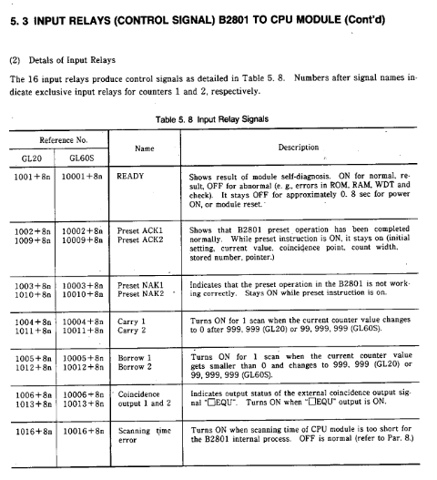
(2) Input relay (B2801 → CPU)
Allocation quantity: 16 points (dual counter)/8 points (single counter)
Core signals: READY, ACK, carry/borrow, coincidence output, scan time error, etc
Response characteristic: The carry/borrow signal only lasts for one scanning cycle
(3) I/O register
Output registers: 4, 1-2 correspond to counter 1, 3-4 correspond to counter 2, store preset values and initial settings
Input registers: 4, storing monitoring data (current value, sampled value, stored data, etc.), supporting multi-mode monitoring
Installation and wiring specifications
(1) Installation requirements
Environmental restrictions: Prohibit direct sunlight, condensation, corrosive gases, and severe vibration environments
Installation operation: The tightening torque of the module fixing screws meets the standard, and the unused slots need to be covered with dust covers
Switch setting: SW1 is used to switch the number of counting bits (OFF=6 bits, ON=8 bits), SW2 is not used
(2) Wiring requirements
Cable selection: Shielded twisted pair cable is used for signal lines, with a length of ≤ 30m (when 50kpps)
Anti interference measures: The distance from the power line is ≥ 30cm, the shielding layer is grounded at a single point, and a filter is installed on the external power supply
Terminal wiring: Signals such as pulse input, external sampling, and counting enable should be wired according to the terminal definition to avoid misconnection
Test run and troubleshooting
(1) Test running process
Before powering on, check the correctness of switch settings, terminal wiring, and voltage levels
Power on self-test: If the RDY indicator light is on, it indicates that the module is normal (self-test for about 0.8 seconds)
Function verification: Operate the pulse generator and observe the status of PHA/PHB (pulse input) and INC/DEC (counting direction) indicator lights
(2) Common troubleshooting
Common causes and solutions for fault phenomena
Non count count enable not activated, pulse input mode error, wiring error check output coil "count enable" status, pulse mode in initial settings, terminal wiring
Counting numerical error, counting digit setting error, pulse counting mode error, external interference confirmation of SW1 switch position, initial setting parameters, wiring anti-interference measures
Coincidentally, the preset value for abnormal output is set incorrectly, the output is disabled but not turned off. Check the preset value parameters and ensure that the output disabled coil is turned off
RDY light goes out, ROM/RAM error, WDT timeout module reset or power off restart, if ineffective, replace the module
Safety regulations
Operation safety: Wiring and maintenance must be powered off, touching live terminals is prohibited to avoid electric shock
Personnel requirements: Installation and wiring must be carried out by professionals to avoid wiring errors that may cause fires or equipment damage
Prohibition of modification: It is not allowed to disassemble or modify modules. Modified products are not covered by warranty and may pose safety risks
- YOKOGAWA
- Reliance
- ADVANCED
- SEW
- ProSoft
- WATLOW
- Kongsberg
- FANUC
- VSD
- DCS
- PLC
- man-machine
- Covid-19
- Energy and Gender
- Energy Access
- Renewable Integration
- Energy Subsidies
- Energy and Water
- Net zero emission
- Energy Security
- Critical Minerals
- A-B
- petroleum
- Mine scale
- Sewage treatment
- cement
- architecture
- Industrial information
- New energy
- Automobile market
- electricity
- Construction site
- HIMA
- ABB
- Rockwell
- Schneider Modicon
- Siemens
- xYCOM
- Yaskawa
- Woodward
- BOSCH Rexroth
- MOOG
- General Electric
- American NI
- Rolls-Royce
- CTI
- Honeywell
- EMERSON
- MAN
- GE
- TRICONEX
- Control Wave
- ALSTOM
- AMAT
- STUDER
- KONGSBERG
- MOTOROLA
- DANAHER MOTION
- Bentley
- Galil
- EATON
- MOLEX
- Triconex
- DEIF
- B&W
- ZYGO
- Aerotech
- DANFOSS
- KOLLMORGEN
- Beijer
- Endress+Hauser
- schneider
- Foxboro
- KB
- REXROTH
- YAMAHA
- Johnson
- Westinghouse
- WAGO
- TOSHIBA
- TEKTRONIX
- BENDER
- BMCM
- SMC
- HITACHI
- HIRSCHMANN
- XP POWER
- Baldor
- Meggitt
- SHINKAWA
- Other Brands
- UniOP
- KUKA
- IBA
- Beckhoff
- ADLINK
-
Beckhoff KL3162 - PLC Module KL 3162
-
Beckhoff EL3255 - PLC module
-
Beckhoff AX5201-0000 - servo driver
-
Beckhoff CX5130-0125 - Embedded PC Intel Atom 1.75GHz processor, 4GB DDR3 RAM
-
Beckhoff CU1521 - industrial switch
-
Beckhoff C6920-1057-0030 - #NAME?
-
B&R 7CP476.60-1 - 1 module 1
-
Beckhoff KL2552 - PLC module
-
Beckhoff CP6223-0002-0060 - #NAME?
-
Unknown BK7350-1060 - EtherCAT bus coupler
-
Beckhoff CX2040-0155 - Automation Basic CPU module, Windows 10 IoT Enterprise
-
Beckhoff CX5230-0175 - 000029724 Embedded PC Industrial PC On Rail
-
Beckhoff EL4134 - PLC Modules
-
Beckhoff EK1100 - automation coupling module EtherCat coupler coupling modules
-
Beckhoff EL6201 - Programmable Controller Module
-
Beckhoff CX2033-0175 - 000107116 embedded PC
-
Beckhoff AM3021-0C40-0000 - #NAME?
-
Beckhoff CX1020-0021 - CPU Module
-
Beckhoff CX2030 - PLC CPU Module
-
Beckhoff CX5130-0120 - PLC Modules
-
Beckhoff CX5230-0175 - 000029724 Embedded Controller Auf Schiene Industrial Pc
-
Beckhoff CX5130-0175 - PC CPU Module HW 4.4 Intel Atom Industrial CX2900 0038 40GB
-
Beckhoff AX5125-0000-0200 - #NAME?
-
Beckhoff KL3011 - One PLC Module
-
Beckhoff CX2020-0120 - 4 GB Basic CPU Module
-
Beckhoff CX1100-0920 - PLC CPU Module Module
-
AB 20F11NC3P5JA0NNNNN - Industrial Automation Part
-
Beckhoff AX5206-0000-0200 - #NAME?
-
Beckhoff CP6700-0001-0050 - , -
-
Beckhoff BECKHOFF-FOR-CX2000-4GB-CFAST-CARD-SLC-FLASH - - - -
-
B&R X67BC6321.L12 - X67 SYSTEM
-
Beckhoff CX9000-0001 - Controller module
-
Beckhoff AX5206-0000-0200 - #NAME?
-
Beckhoff CP2919-0000 - Multitouch Built In Control Panel 24VDC 19"
-
Beckhoff CP6032-0000-0010 - - 15" OPERATOR CONTROL PANEL
-
Beckhoff KL2791 - PLC module
-
Beckhoff CP7902-0001-0000 - - Touch Panel Power Supply 24VDC
-
Beckhoff CP6702-0001 - Open Interface Panels
-
Beckhoff CU8800-0010 - Communication / Interface Module Module
-
Beckhoff C6920-0010 - Driver
-
Beckhoff EL6614 - EtherCAT / Bus Terminal
-
Beckhoff AX5203-0000-0200 - #NAME?
-
Beckhoff EK1322 - 2 port EtherCATP junction Rev 0017
-
Beckhoff EP2349-0021-16 - EtherCAT Box - 16 Channel Module
-
Beckhoff CP6801-0021-0010 - Touch Panel - 12" 14 1 1020
-
Beckhoff CX1020-0112 - - N00 N010 CX1100 0004 PLC CONTROLLER R1S13.7
-
Beckhoff EL2784 - EtherCAT / Bus Terminal Module
-
Beckhoff CX2020-0155 - PLC CPU Module Module
-
Beckhoff EK1914 - PLC EK 1914 Module
-
Beckhoff Cx5130-0122 - PLC CPU Module
-
Beckhoff CX5010-0112 - CPU module
-
Beckhoff CP7811-0001 - - 0 0
-
Beckhoff EL3162 - controller module
-
Beckhoff CU2508-0000 - 8 Port Port Multiplier PLC Processor
-
Beckhoff CX5010-1112 - Mod CPU Module K Bus Windows Runtime TwinCAT 2 NC
-
Beckhoff BECKHOFF-CX2100-0914-CX21000914 - Industrial Automation Part
-
Beckhoff CX1500-M310 - PLC Module
-
B&R 7CP476.60-1 - 1 module 1
-
Beckhoff EL5042 - EtherCAT / Bus Terminal
-
B&R AT6402 - X20 PLC MODULE X20 ORIGINAL
-
Beckhoff CP7802-1327-0010 - #NAME?
-
Beckhoff CX1100-0002 - Power Module
-
Beckhoff CX2040-0155 - PLC CPU Module
-
Beckhoff EP1809-0021 - PLC Modules
-
Beckhoff CX2040 - 0142 Communication Module
-
Beckhoff CX2900-0033 - PLC CPU Module
-
Beckhoff CX2500-0030 - Interface Module
-
Beckhoff EK1100 - Module Ethernet Kommunikaton Modul
-
Beckhoff KL4428 - Bus Terminal 8 Channel Analog Output
-
Beckhoff CX5130-0122 - embedded PC CPU module 4 GB industrial PC CPU module HW 3.5
-
Beckhoff CX9020-0111-1002 - PLC CPU Module
-
Beckhoff CP6929-0001-0000 - Touchscreen Panel 6.5" ELO Model -
-
Beckhoff EP4174-0002 - Module HTP0
-
Beckhoff CP6092-0011-0000 - - Touch Screen 15" Panel
-
B&R 5WCC00000440K0-001 - PANEL PC 2100 SYSTEM UNIT AUTOMATION PANEL
-
Beckhoff CX2100-0014 - Original
-
Beckhoff CX5120-0115 - 3243
-
Beckhoff CP3919-1039-0011 - Multi Touch Control Panel - 19" G190ETN01.2
-
Beckhoff CX9001-0101 - PLC Module QW
-
Beckhoff BECKHOFF-CX5120-121 - Industrial Automation Part
-
Beckhoff BECKHOFF-BX8000-0000 - Industrial Automation Part
-
Beckhoff AX511200000200 - AX5112 0000 0200 Servo Driver
-
Beckhoff EL2564 - EtherCAT Terminal, 4 channel LED output, 5 8VDC, 4A, RGBW
-
Beckhoff KL4494 - EtherCAT / Bus Terminal
-
B&R 5e9000.17 - Control Panel
-
Beckhoff BX8000 - PLC Module
-
Beckhoff AS1060-0110 - , Stepper Motor Precision .........
-
B&R 0702-10B - 6PPT50. Touch Panel
-
Beckhoff C6930-0050 - Schaltschrank Industrie Pc Core i7 4700 CPU+FC9062 Module
-
Beckhoff KL2702 - PLC Controller Module
-
Beckhoff EL4038 - Communication Module
-
Beckhoff EK1110-0008 - EtherCAT / Bus Terminal Module
-
Beckhoff CX5020-0111 - PLC CPU Module
-
Beckhoff CP7232-0001-0050 - #NAME?
-
Beckhoff FC3101-0000 - communication module
-
Beckhoff EL6930 - EtherCAT Klemme
-
Beckhoff EL6631 - EtherCAT / Bus Terminal
-
Beckhoff EK1100 - ,EL2202,EL1904,EL1809,EL9189,EL9188,EL2809,EL3122,EL3102,EL4102
-
Beckhoff EL6695 - EtherCAT / Bus Terminal
-
Beckhoff CX1500-M510 - CX1020 N000 CX1020 0011 CX1100 0002 Controller Set
-
Beckhoff AM8052-1F20-0000 - - motor -
-
Beckhoff C6925-1004 - Industrial PC
-
Beckhoff 7132-0001 - CPPC
-
Beckhoff CP6001-0011-0010 - - Control Panel 12 inch TFT Display, 001...
-
Beckhoff CX2020-0120 - 4GB CPU ,CX2100 0904 3x EL6900, EL1904 16 GB Memory
-
Beckhoff C6920-0030 - Controller
-
B&R 3DM486.6 - DIGITAL MIXED MODULE DM486
-
Beckhoff KL3361 - PLC Module KL 3361
-
Beckhoff C9900-H391 - operating system
-
Unknown CKS-10T - Industrial Automation Part
-
Beckhoff AX5206-0000 - server Driver
-
Beckhoff CP6800-0001-000 - #NAME?
-
Beckhoff CX1100-0920 - Module 24VDC Controller Module
-
Schneider 140CRP31200 - IPC PLC Module In Box
-
Beckhoff C6930-1001 - Industrial PC
-
Beckhoff FC9002 - FC 9002 Ethernet PCI Network Card
-
Beckhoff EL6070-1296 - license key terminal EtherCAT
-
Beckhoff CP7721-1036-0010 - Display Control Panel
-
Beckhoff FC3101 - 2022 Module
-
Beckhoff EK9300-1007 - EtherCAT / Bus Terminal Module
-
Beckhoff AX8640-0000-0000 - #NAME?
-
Beckhoff CP7932-0001-0000 - - touch screen -
-
Beckhoff CX5020-0110 - HW Version 3.4 CPU Module
-
Beckhoff CP2912-0000 - touch screen in box
-
Beckhoff AX5118-0000-0200 - #NAME?
-
B&R 2EX302.5 - Extension unit EX302
-
Beckhoff CX5140-0111 - 1884
-
Beckhoff EQ8003-2042 - Ethercat I o Module

K-JIANG

Add: Jimei North Road, Jimei District, Xiamen, Fujian, China
Tell:+86-15305925923