
K-WANG


YASKAWA Machine Controller MP2000 Series
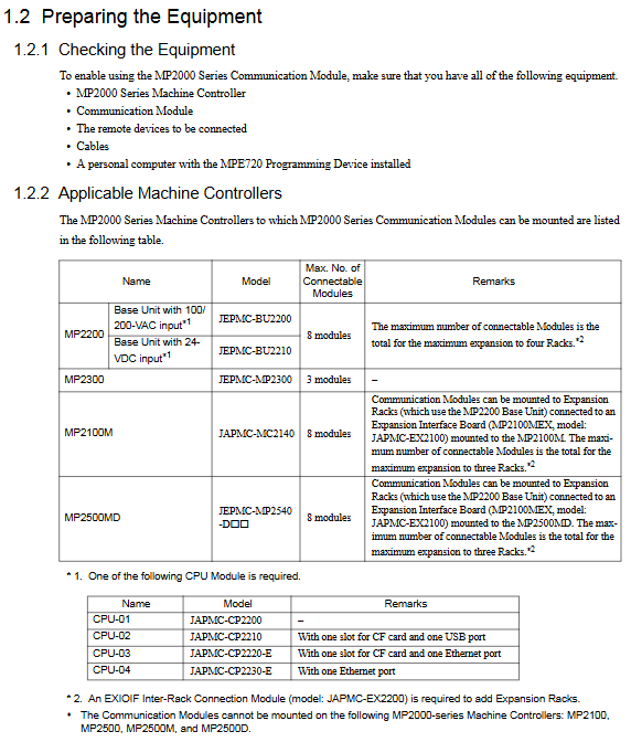
Adaptive controller: MP2000 series machine controller (MP210M, MP2200, MP2300, MP2500MD)
Core functions: Support multi protocol industrial communication, data transmission between devices, engineering debugging and maintenance, and adapt to various interfaces such as RS-232C, Ethernet, DeviceNet, etc
YASKAWA Machine Controller MP2000 Series
Core positioning
Applicable products: JAPMC-CM23 model communication module, including 6 sub models: 218IF-01, 218IF-02, 217IF-01, 260IF-01, 261IF-01, 215AIF-01
Adaptive controller: MP2000 series machine controller (MP210M, MP2200, MP2300, MP2500MD)
Core functions: Support multi protocol industrial communication, data transmission between devices, engineering debugging and maintenance, and adapt to various interfaces such as RS-232C, Ethernet, DeviceNet, etc
Hardware specifications and installation configuration
1. Core parameters of the module
Module model, communication interface, key specifications, protection level, weight
218IF-01 RS-232C+Ethernet (10Base-T) serial port up to 19.2kbps; Ethernet 10Mbps, TCP/UDP protocol IEC IP00 85g
218IF-02 RS-232C+Ethernet (10Base-T) supports Ethernet (LP) mode, with larger engineering message size IEC IP00-
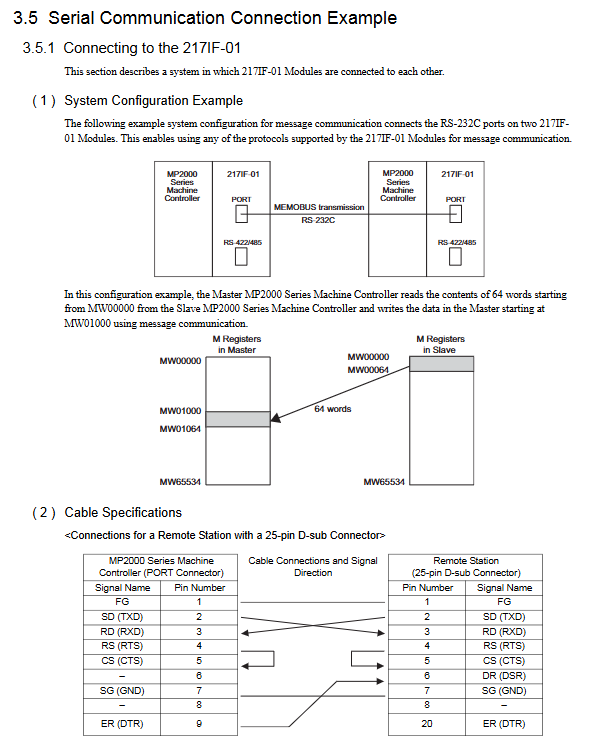
217IF-01 RS-232C+RS-422/485 serial port up to 19.2kbps, half duplex/full duplex optional IEC IP00-
260IF-01 RS-232C+DeviceNet supports DeviceNet master-slave communication, explicit/implicit message IEC IP00-
261IF-01 RS-232C+PROFIBUS compatible with PROFIBUS protocol, industrial bus communication IEC IP00-
215AIF-01 RS-232C+MPLINK/CP-215 supports token passing mechanism and link communication function IEC IP00-
2. Installation and wiring requirements
Environmental conditions: working temperature ≤ 55 ℃, no corrosive gases, vibration ≤ 9.8m/s ², avoid direct sunlight and condensation
Installation specifications: The module needs to be aligned with the guide rail and inserted into the controller slot, with a bolt tightening torque of 2.94N · m. Unused slots need to be equipped with dust covers
Wiring requirements: The distance between the control signal and the power line should be ≥ 30cm, and the grounding wire should be as short as possible (single point grounding); RS-422/485 adopts a 4-wire wiring system and requires 120 Ω terminal resistors to be connected at both ends
Port protection: The FG terminal needs to be reliably grounded, and the cable shielding layer should be connected to the equipment casing to avoid electromagnetic interference
Communication mode and protocol system
1. Three major communication modes
Message communication: Triggered through MSG-SND/MSG-RCV functions, supporting master-slave data exchange and adapting to multiple protocols (MEMOBU, MELSEC, etc.)
Engineering Communication: Used for debugging communication between MPE720 programming software and controller, supporting interfaces such as serial port and Ethernet
Link communication: only applicable to 215AIF-01 module, automatically timed transmission of preset I/O data, based on token passing mechanism
2. Core Communication Protocol
Protocol Name Applicable Interface Core Features Application Scenarios
MEMOBU serial/Ethernet YASKAWA standard protocol, master-slave communication, supports coil/register read/write data transmission between devices of the same brand
Extended MEMOBU Ethernet/MPLINK Extended MEMOBU, supporting up to 508 words of data transmission for large data volume industrial communication
MELSEC serial/Ethernet compatible with Mitsubishi MELSEC PLC, supporting communication between CPUs, buffering communication, and cross brand PLC interconnection
MODBUS/TCP Ethernet Industrial General Protocol, client/server mode, cross vendor device compatible communication
OMRON serial port compatible with Omron SYSMAC PLC, Host Link mode Omron device integration
Non protocol full interface without preset protocol, directly transmitting continuous register data custom protocol scenario
DeviceNet 260IF-01 module device network protocol, supports explicit/implicit message industrial bus device interconnection
Software Configuration and Programming Implementation
1. Basic configuration process
Communication Manager Settings: Configure logical ports (up to 16), select port types such as serial/Ethernet/CP-215, and set parameters such as baud rate and IP address
Self configured execution: triggered by the DIP switch or MPE720 software of the controller, automatically identifies the module and generates a configuration file
MPE720 parameter settings: Start programming software and configure project communication parameters (logical port, IP address, protocol type)
Transmission definition configuration: Set transmission protocol, master-slave mode, data address, timeout time, etc. for different modules
2. Core programming functions
MSG-SND (Message Sending Function): sends data to remote devices, supports multi protocol selection, core parameters include execution bit, device type, protocol type, circuit number, parameter list address
Input parameters: Execute (start send), Abort (interrupt send), Dev Typ (device type), Pro Typ (protocol type), etc
Output parameters: Busy (processing), Complete (sending completed), Error (sending error)
MSG-RCV (Message Reception Function): Receive remote device data, support automatic/manual reception switching, core parameters correspond to the sending function
Support data offset storage, receive range limitation, and can monitor communication status and error messages
3. Programming Example Scenarios
218IF-01 Ethernet Communication: Master (IP 192.168.1.2) and Slave (IP 192.168.1.3) transmit 100 word data via UDP using Extended MEMOBU protocol
MELSEC PLC connection: Read the D0000-D0063 register data of Mitsubishi PLC, store it in controller MW10000-MW10063, and automatically convert it through MELSEC protocol
Non process protocol communication: Unidirectional transmission of 254 word continuous register data, no response mechanism, suitable for custom protocol interaction
Detailed operation of each module (taking 218IF-01/02 as an example)
Module 218IF-01
Interface specifications: RS-232C (9-pin D-sub)+Ethernet (RJ-45), supporting TCP/UDP protocols
Key settings:
Ethernet parameters: IP address (default 192.168.1.1), subnet mask 255.255.255.0, port numbers 256-65535
Serial port parameters: data bits 7/8, parity bits (odd/even/none), stop bits 1/2, baud rate 9600/19200bps
Communication example: Ethernet connection between modules, Master reads Slave's MW00000-MW00063 data through MSG-SND and stores it locally in MW01000-MW01063
Module 218IF-02
Core advantages: Supports Ethernet (LP) mode, larger engineering message size, faster communication speed
Unique settings: Ethernet (LP) is selected as the logical port, 9999 is set as the engineering port, and the IP address is compatible with 218IF-01
Connection example: Ethernet connection with a personal computer, engineering debugging through MPE720 software, supporting high-speed data transmission
Maintenance and troubleshooting
1. Key points for regular maintenance
Daily inspection: Terminal fastening, cleaning of heat sink (compressed air blowing), no damage to cables
Component replacement cycle: cooling fan 2-3 years, smoothing capacitor 5 years, motor bearing 2 years/12000 hours, fuse 10 years
Safe operation: Before maintenance, the power must be cut off and wait for the capacitor to discharge (CHARGE LED to turn off); Use insulated tools and do not touch CMOS components
2. Common troubleshooting
Common causes and solutions for fault phenomena
Communication timeout (ERROR light on) IP address conflict, port number error, transmission parameter mismatch check network configuration, unified baud rate/checksum and other parameters
Data transmission error: loose wiring, ungrounded shielding layer, electromagnetic interference: re tighten terminals, optimize wiring (away from power lines), and rectify grounding
Hardware malfunction (ERR light flashing) ROM/RAM error, module not recognized, perform self diagnostic test, replace control board, reinstall module
Ethernet connection failure, network cable damage, switch failure, IP configuration error. Replace the network cable, check the switch status, and confirm that the IP is in the same network segment
3. Fault reset method
Trigger reset input signal, press the [RESET] button on the operator, turn off the main circuit power and restart
Reset premise: eliminate the cause of the fault and turn off the external operation command (FWD/REV/ORT)
- YOKOGAWA
- Reliance
- ADVANCED
- SEW
- ProSoft
- WATLOW
- Kongsberg
- FANUC
- VSD
- DCS
- PLC
- man-machine
- Covid-19
- Energy and Gender
- Energy Access
- Renewable Integration
- Energy Subsidies
- Energy and Water
- Net zero emission
- Energy Security
- Critical Minerals
- A-B
- petroleum
- Mine scale
- Sewage treatment
- cement
- architecture
- Industrial information
- New energy
- Automobile market
- electricity
- Construction site
- HIMA
- ABB
- Rockwell
- Schneider Modicon
- Siemens
- xYCOM
- Yaskawa
- Woodward
- BOSCH Rexroth
- MOOG
- General Electric
- American NI
- Rolls-Royce
- CTI
- Honeywell
- EMERSON
- MAN
- GE
- TRICONEX
- Control Wave
- ALSTOM
- AMAT
- STUDER
- KONGSBERG
- MOTOROLA
- DANAHER MOTION
- Bentley
- Galil
- EATON
- MOLEX
- Triconex
- DEIF
- B&W
- ZYGO
- Aerotech
- DANFOSS
- KOLLMORGEN
- Beijer
- Endress+Hauser
- schneider
- Foxboro
- KB
- REXROTH
- YAMAHA
- Johnson
- Westinghouse
- WAGO
- TOSHIBA
- TEKTRONIX
- BENDER
- BMCM
- SMC
- HITACHI
- HIRSCHMANN
- XP POWER
- Baldor
- Meggitt
- SHINKAWA
- Other Brands
- UniOP
- KUKA
- IBA
- Beckhoff
- ADLINK
-
Beckhoff CX1100-0910 - Power Supply Module
-
Beckhoff C5210-0010 - Communication Module C5210
-
BECKHOFF KL1352 - Bus Terminal SET OF 2 FREE FAST SHIP
-
Beckhoff EL3058 - 8 x analog input single ended 4...20mA 85惟 shunt 12bit
-
Beckoff CX1100-0920 - UPS Module 24VDC (US SELLER) * *
-
BECKHOFF C6920-0000 - C69200000 PLC Moudule
-
Beckhoff CX5120-0115 - CPU controller module CX5120-0115
-
Unknown 15F5C1E-Y50A - Of Frequency Converters
-
Beckhoff AX5118-0000-0200 - Servo Drive HTP0
-
BECKHOFF AX5106-0000-0200 - Servo Drive
-
Beckhoff CX5240-0175 - Module (free) #U2327D YG
-
Beckhoff CP6607-0001-0000 - Compact PC Panel Economy Installation Operator 5,7 "
-
Beckhoff EP3744-0041 - 2022 EP37440041 Module
-
Beckhoff CP6209-0001-0020 - 6.5" PC Touch Screen Control Panel 24VDC
-
Beckhoff CX9020-0111 - /U900 +8x+2xEL3121+1x EL9410+3xEL1008+1x EL2008 Set
-
Beckhoff C6525-1030-0050 - Industrial PC
-
Beckoff CX1100-0920 - UPS Module 24VDC (US SELLER)
-
Beckhoff CX5010-0120 - CX5010 Processor Intel Atom Z510 B24
-
Siemens 6FC5203-0AF04-1BA1 - Operation Panel
-
Beckhoff CX5230-0175 - / 000029724 Embedded PC / Industrial PC on Rail
-
Beckhoff CP3916-0000 - industrielles Anzeige- und Bedienterminal
-
BECKHOFF CX1500-M310 - CX1000-N000 CX1000-0011 CX1000-C00L CX1100-0002 PLC Module
-
Beckhoff EL1872 - 16-channel digital input terminal
-
BECKHOFF EP2318-0001 - module
-
Beckhoff CX9020-0110 - Basic CPU Module
-
Beckhoff EL2564 - EtherCAT Terminal, 4-channel LED output, 5鈥?8VDC, 4A, RGBW
-
Beckhoff CX5130-0155 - /000105637 Automation Embedded PC
-
B&R 400 - Power Control Panel Rev D0 24 VDC
-
Beckhoff CX2020-0155 - module
-
Beckhoff CX9020-0115 - PLC Module
-
BECKHOFF EL6695 - PLC EL 6695
-
BECKHOFF EL7047 - PLC Modules
-
Beckhoff CX1000-0012 - Control HW 2.2 + CX1500-M310 + CX1000-C00L + CX1100-0002+
-
Beckhoff C6920-1039-0030 - control cabinet industrial PC CPU Celeron 1.90 GHz, 2 cores
-
BECKHOFF CX1100-0910 - PLC Module#
-
Beckhoff IL2301-B318-0000 - Coupler Box 4 Channel Digital Input |
-
Beckhoff CX7080 - Module
-
Beckhoff C6930-0060 - Industrial PC
-
Beckhoff CP7902-1060-0000 - Touchscreen 15 " CP7902
-
beckhoff CX9020-0111 - Controller module or UPS
-
Beckhoff CX8091 - PLC Module CX8091
-
Beckhoff C6640-1008-0030 - Control Cabinet Industrial PC
-
BECKHOFF CX1100-0920 - module
-
Beckhoff C9900-M921 - see pictures
-
BECKHOFF CP6829-0001-0000 - Touch Panel
-
BECKHOFF C6930-0060 - Industrial Computer
-
BECKHOFF CX8050 - PLC module
-
Beckhoff CP6202-0021-0020 - Touch Screen #
-
BECKHOFF AM3031-0C20-0000 - SERVO MOTOR
-
Unknown BCH1302N11A1C - Servo motor
-
Beckhoff EL2502 - 2-channel pulse width output terminal
-
Beckhoff EL6731 - Profibus Master / *Rev: 0025
-
Beckhoff CP3918-0010 - Control Panel
-
BECKHOFF CP2915-0010 - [24 MONTH WARRANTY] Control Panel
-
Beckhoff AX5203-0000-0202 - Servo Drive
-
Schneider TSXDSY64T2K - PLC OUTPUT MODULE
-
Beckhoff EP4174-0002 - Module-
-
Beckhoff IL2302-B318-0000 - Profibus Box
-
Beckhoff CP6709-0001-0000 - Touchpanel
-
BECKHOFF CX2030-0123 - Controller
-
Beckhoff CX9020-0111 - Processor Module
-
Beckhoff CX1020-0000 - CX Basic CPU Module
-
Beckhoff AX2003-AS - Servo Drive HTP0
-
Beckhoff C6240-1052-0040 - 4-086-06-3073 Industrial Computer CB1052-0003
-
Beckhoff EL1918 - 8 xTwinSAFE Input
-
Beckhoff AM8072-0R20-0000 - Servomotor
-
BECKHOFF AM8021-1B21-0000 - servo motor #T882 YS
-
Beckhoff EL6224 - 4 X Terminal IO-LINK
-
Beckhoff CX5140-0135 - embedded PC with Intel Atom processor 4 GB HW 3.6
-
Beckhoff CP7201-1000-0000 - Panel PC #
-
Beckhoff CX5130-0121 - Embedded-PC 4GB CPU Module HW 2.5 Industrial PC
-
Beckhoff AM8022-0D41-1002 - Servomotor
-
BECKHOFF CX2030-0130 - Module
-
BECKHOFF EL1872 - 16-channel digital input terminal
-
Unknown GXMMW.A203P33 - 1pc encoder
-
Beckhoff EL6631-0000 - EtherCAT Terminal 2-Port EL 6631
-
BECKHOFF C6925-0030 - Industrial Computer
-
Beckhoff CX8190 - A Module
-
BECKHOFF CX2040-0135 - CX2040-0135/000000927 CPU BASE MODULE i7 2715QE 2.1GHz --
-
BECKHOFF KL6023-0000 - Wireless adapter
-
Saia Burgess PCD7.F700 - PCD7F700 Communication Module
-
Beckhoff CX5130-0112 - CPU Module
-
BECKHOFF CX1020-N010 - CX1020-N000 CX1020-0111 CX1100-0004 EL2008 EL3064 EL4004
-
Beckhoff EP1819-0021 - A Module
-
Beckhoff CX2030-0120 - / 4gb with CX2100 0004
-
B&R X20-XC-0292 - Automation Powerlink Ethernet Bus Controller Module
-
Beckhoff BK3110 - One PLC Module
-
BECKHOFF KL3222 - PLC Module
-
BECKHOFF CX1500-M310 - CX1000-N000 CX1000-0011 CX1000-C00L CX1100-0002 PLC MODULE
-
Beckhoff CP3918-0010 - Control Panel
-
Beckhoff CX2030-0100-1002 - /4GB + CX2100 + CX2550 + CX2500-0060 + SSD
-
Beckhoff EP1816-0008 - PLC Module
-
Beckhoff CX5130-0112 - Module
-
Beckhoff Cx1500-m750 - CPU Hw: 1.4
-
BECKHOFF AX5112-0000-0200 - AX511200000200 Servo Driver
-
Beckhoff EL3751 - EtherCAT Terminal 1 Channel Analog Input Multifunction 24 Bit
-
Beckhoff CX1100-0002 - Power Supply Module
-
Beckhoff CP3916-1016-0010 - Control Panel
-
BECKHOFF CX9001-1101 - #NAME?
-
Beckhoff EP3174-0002 - EtherCAT Box Module
-
Beckhoff C6030-0070 - servo drive
-
Beckhoff CX2020-0120 - /4GB CPU, CX2100-0904, 3x EL6900, EL1904, 16GB Memory
-
BECKHOFF C6110 - BOX-PC 113608
-
BECKHOFF EK1914 - module #P
-
Beckhoff C6140 - Ipox IP-4GVI63 + CH7009A_DVI_TV + SIEMENS A5E00369843 + WD800AAJB
-
Beckhoff CX5020-0111 - controller Good quality
-
BECKHOFF C6015-0010 - / 6559380 ULTRA-COMPACT INDUSTRIAL PC ()
-
Beckhoff AX5203-0000-0200 - PLC module
-
Beckhoff EL2872 - 16-channel digital output terminal
-
BECKHOFF C3640-0000 - Panel Industrial PC 100/240VAC 128MB E0122L
-
Beckhoff CX8031 - Module
-
Beckhoff CX5020-0120-1002 - PLC module#
-
Beckhoff C6140 - M845B + SIEMENS A5E00369843 + C9900_A159_1 + AUTOMATA CAN PCI 1N
-
BECKHOFF AX5112-0000-0200 - Servo Drive*ie
-
B&R ECPA42-01 - Analog Output Module 4-Channel, +/- 10V Output Signal, 20mA Max
-
Beckhoff EL6631-0010 - PLC Module
-
BECKHOFF C6930-0070 - CONTROL CABINET INDUSTRIAL PC
-
BECKHOFF AX5112-0000-0200 - AX511200000200 Servo Driver
-
BECKHOFF EK9000 - Programmable Logic Controller Module EK9000 EK9000
-
BECKHOFF C6920-1028-0000 - Industrial computer
-
Beckhoff CX2030-0120 - controller Module
-
Beckhoff BX8000-0000 - Bus Terminal Controller HW 4.4
-
B&R 3NC154.60-2 - Positioning Module#
-
BECKHOFF CX1020-0122 - PLC module
-
Beckhoff AM3032-0D40-0000 - Servo Motor
-
BECKHOFF CX5020-0111 - CPU Module CX5020-0111
-
Beckhoff CB1051 - G5 Motherboard
-
BECKHOFF KL2641 - 1-channel relay output terminal

K-JIANG

Add: Jimei North Road, Jimei District, Xiamen, Fujian, China
Tell:+86-15305925923