
K-WANG


HIMA HIMatrix MI 24 01 Safety Related Controller Module
HIMA HIMatrix MI 24 01 Safety Related Controller Module
Product core positioning
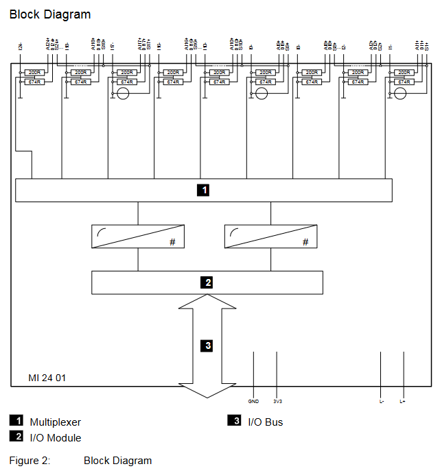
MI 24 01 is a modular safety related input module launched by HIMA (Paul Hildebrandt GmbH+Co KG) in Germany, specifically designed for the HIMatrix F60 modular control system. Its core function is to achieve safe acquisition and fault monitoring of 24 analog or digital signals, suitable for scenarios with high safety requirements such as petrochemical, energy, and process industries (such as SIL 3 safety circuits). The module supports software configuration as analog input (0/4~20 mA current signal) or digital input (proximity switch, safety contact, etc.), with safety features such as fault self diagnosis, signal isolation, overcurrent/overvoltage protection, and complies with international safety standards such as IEC 61508 (SIL 3), EN 954-1 (Cat. 4), and EN ISO 13849-1 (PL e).
Key technical specifications
1. Core input capability
Category specific parameters
The number of input channels is 24, which cannot be used as both analog and digital signals at the same time. It needs to be configured independently for a single channel
Analog Input (AI) - Signal Type: 0/4~20 mA Unidirectional Current Signal
-Input resistance: 200 Ω
-Measurement accuracy: ± 0.2% full range at 25 ℃, ± 0.5% full range over full temperature range
-Resolution: 12 bits
-Sampling time: Approximately 45 μ s per channel, refresh rate synchronized with F60 system cycle
Digital Input (DI) - Compatible with EN 60947-5-6 standard proximity switches, safety proximity switches, contacts with resistance wiring
-Nominal input resistance: 674 Ω
-Short circuit current (proximity switch power supply): 12.2 mA
-Response delay: 2 x F60 cycles in L → H direction, H → L direction needs to be combined with filtering configuration
Power output is divided into 3 independent power supply groups (corresponding to channels 1-8, 9-16, 17-24), with a maximum output current of 200 mA per group. It supports switching between 8.2 VDC/26 VDC and has short-circuit protection (restart after 30 seconds of overload, retry after 60 seconds of continuous overload)
2. Physical and environmental parameters
Range of environmental parameter specifications
Working temperature: 0 ℃~+60 ℃ (normal environment inside industrial control cabinet)
Storage temperature -40 ℃~+85 ℃ (for transportation and inventory scenarios)
Protection level module body IP20 (requires overall protection with F60 cabinet, and additional IP54 enclosure for explosion-proof scenarios)
Altitude limit<2000 meters (no need to downgrade)
Pollution Level II (IEC/EN 61131-2, applicable to minor pollution in industrial environments)
Size and Weight - Size: 6 RU height, 4 HP width (compatible with F60 standard rack)
-Weight: 580 g
The power supply requirement is 24 VDC (-15%~+20% fluctuation), provided by the F60 system power module, with a typical power consumption of 5.5 W (no-load) and a maximum power consumption of 16 W (full load)
3. Safety and Compliance
Specific compliance items of certification standards
Functional Safety Standard - IEC 61508: SIL 3 (Safety Integrity Level)
-EN 954-1: Cat. 4 (safety category)
-EN ISO 13849-1: PL e (performance level)
-ATEX/IECEX: Zone 2 hazardous area adaptation (to meet EN 60079-15 enclosure requirements)
Electromagnetic compatibility (EMC) EN 61000-4-2 (electrostatic discharge), EN 61000-4-5 (surge), EN 55022 (radiated emission Class A)
Electrical Safety IEC/EN 61131-2 (Protection Class III) UL 61010-1、CSA C22.2 No. 61010-1
Core functions and fault handling
1. Signal conditioning and safety monitoring
Filtering and anti-interference: Analog input supports software configuration of low-pass filtering (to suppress high-frequency noise), while digital input can enable "noise blanking" (the signal needs to last for 2 system cycles to be recognized to avoid false triggering by surges, but it will increase response delay);
Fault self diagnosis:
Channel level fault: Monitor open circuit (signal<lower limit value), short circuit (signal>upper limit value), abnormal A/D conversion, measurement value exceeding the safe accuracy range. After triggering, set the corresponding error code and light up the ERR light;
Module level faults: power supply abnormality, data bus fault, temperature exceeding limit (FTT test), triggering to cut off power supply to the fault group and report to the system;
Safety response logic: When there is an analog fault, set AI. Error Code>0. When there is a digital fault, output a low level according to the "power loss trip" principle to ensure that the system enters safe mode in the event of a fault.
2. Status indication and operation
LED indicator light status and meaning
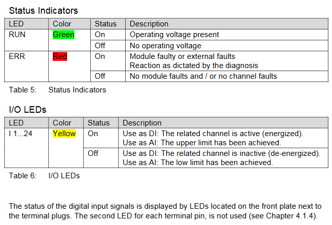
RUN (green) constantly on: module power supply is normal; Extinguished: No power supply or module failure
ERR (red) constantly on: module or channel failure; Extinguish: No malfunction
I 1-24 (yellow) constantly on (DI mode): channel activated (powered on); Always on (AI mode): Measurement value reaches the upper limit; Extinguished: Channel not activated or reaching lower limit
Installation and Configuration
1. Physical installation
Rack adaptation: Only supports HIMatrix F60 modular rack, installed in slots 3-8 (slot 1 for power module, slot 2 for CPU module);
Installation steps:
Disconnect the system power and remove the cables from the front panel of the rack;
Insert the module along the upper and lower rails of the rack, press the front panel until it clicks into place with the back panel socket;
Fix the upper and lower ends of the module with screws and reconnect the cables;
Explosion proof installation (Zone 2): It needs to be installed in an enclosure with a protection level of IP54 or above, ensuring heat dissipation (maximum power consumption of the module is 16 W), and using PELV/SILV level 24 VDC power supply.
2. Wiring specifications
Cable requirements: Both analog and digital inputs must use shielded twisted pair cables, with the shielding layer grounded at one end (controller side), and a total resistance of ≤ 250 Ω (analog) and ≤ 50 Ω (digital);
Pin allocation: 24 channels are divided into 3 groups, each group of pins including "power supply (Sx+), ground (Ix -), digital input (DIx+), analog input (AIx+)". Example (channels 1-8):
Pin Identification Function Description
A 01 S1+channels 1-8 power output
A 02 I1- Channel 1 Grounding
B 01 DI1+Channel 1 Digital Input
B 02 AI1+Channel 1 Analog Input
3. Software configuration
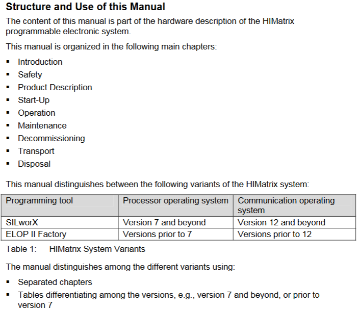
Tool adaptation:
System firmware<V7: configured using ELOP II Factory;
System firmware ≥ V7: Use SILworX (recommended, supports graphical interface);
Core configuration items:
Channel Type (AI/DI): Single channel independent setting Channel Used [BOOL] (1=enabled, 0=disabled);
Threshold configuration: Limit Value LOW/HIGH (DI mode: effective high and low level range; AI mode: under/over range threshold), Hysteresis LOW/HIGH (DI mode: switching threshold);
Power supply settings: Transmitter Voltage (8.2 V/26 V switching per group), Transmitter Used [BOOL] (whether to use module power supply).
Ordering and matching
1. Core components and spare parts
Component Name Model/Part Number Description
MI 24 01 module 98 2200115 24 channel safety input module (with normal coating, non optional uncoated version)
Two wire transmitter protection module 99 4703202 (H 7032) is compatible with two-wire transmitters and has SIL 3 safety protection
Three wire transmitter protection module 99 4703302 (H 7033) is compatible with three wire transmitters and has SIL 3 safety protection
The terminal plug does not have a clear part number for the module front board wiring terminal, and needs to be ordered separately
2. Documentation and technical support
Essential documents:
《HIMatrix System Manual Compact Systems》(HI 800 141 E);
《HIMatrix Safety Manual》(HI 800 023 E);
SILworX Online Help or ELOP II Factory Online Help;
Technical Support: HIMA Germany Headquarters (Phone+49 6202 709-0, Email) info@hima.com )Or regional agents (such as document provider SDS Automatyka).
Maintenance and lifecycle
Regular maintenance: Conduct precision calibration (analog input) and functional verification (safety circuit proof test) every 10 years;
Fault replacement: After a module failure, it needs to be replaced as a whole (cannot be repaired on site). When replacing, the system power supply needs to be disconnected, and the same model or HIMA certified replacement model should be used;
Scrap disposal: It is necessary to dispose of industrial electronic waste in accordance with the regulations. You can contact HIMA to sign a disposal agreement.
Key precautions
Channel configuration restrictions: 24 channels cannot be mixed into AI/DI mode and must be configured uniformly or grouped;
Power overload protection: Each group can provide a maximum of 200 mA of power. After overload, it will automatically restart within 30 seconds. If the overload persists, it will retry within 60 seconds. It is necessary to avoid connecting too many high-power devices to a single group;
Explosion proof scenario requirements: Zone 2 installation must meet EN 60079-15 enclosure protection (IP54+) and be labeled with "power-off operation only";
Software compatibility: The ELOP II Factory project and SILworX project are non editable, and compatibility needs to be confirmed before upgrading firmware.
- YOKOGAWA
- Reliance
- ADVANCED
- SEW
- ProSoft
- WATLOW
- Kongsberg
- FANUC
- VSD
- DCS
- PLC
- man-machine
- Covid-19
- Energy and Gender
- Energy Access
- Renewable Integration
- Energy Subsidies
- Energy and Water
- Net zero emission
- Energy Security
- Critical Minerals
- A-B
- petroleum
- Mine scale
- Sewage treatment
- cement
- architecture
- Industrial information
- New energy
- Automobile market
- electricity
- Construction site
- HIMA
- ABB
- Rockwell
- Schneider Modicon
- Siemens
- xYCOM
- Yaskawa
- Woodward
- BOSCH Rexroth
- MOOG
- General Electric
- American NI
- Rolls-Royce
- CTI
- Honeywell
- EMERSON
- MAN
- GE
- TRICONEX
- Control Wave
- ALSTOM
- AMAT
- STUDER
- KONGSBERG
- MOTOROLA
- DANAHER MOTION
- Bentley
- Galil
- EATON
- MOLEX
- Triconex
- DEIF
- B&W
- ZYGO
- Aerotech
- DANFOSS
- KOLLMORGEN
- Beijer
- Endress+Hauser
- schneider
- Foxboro
- KB
- REXROTH
- YAMAHA
- Johnson
- Westinghouse
- WAGO
- TOSHIBA
- TEKTRONIX
- BENDER
- BMCM
- SMC
- HITACHI
- HIRSCHMANN
- XP POWER
- Baldor
- Meggitt
- SHINKAWA
- Other Brands
- UniOP
- KUKA
- IBA
- Beckhoff
- ADLINK
-
Beckhoff CP6500-1012-0060 - Control Cabinet PC Interface Unit
-
Beckhoff FC5202-0000 - 2-Channel DeviceNet Master PCI Interface Card
-
Beckhoff CP6606-0001-0020 - 7-Inch Economy Panel PC Touch
-
Beckhoff CP2921-0010 - Multi-Touch Integrated Control Panel Display
-
Beckhoff CP7802-0001-0010 - 15-Inch Touch Screen Control Panel HMI
-
Beckhoff C6920-0050 - Control Cabinet Industrial PC
-
Beckhoff BK9105 - EtherNet/IP Bus Coupler Network Interface
-
Beckhoff 31 Modules - Bus Terminal Slice I/O Lot Assortment
-
Beckhoff CX2020-0120 - Embedded PC Basic CPU Module 8GB CFast Card
-
Beckhoff CP7001-0000 - HMI Control Panel Touch Screen
-
B&R 7EX484.50-1 - System 2005 Controller Base Module Slots
-
Beckhoff EK1322 - 2-Port EtherCAT P Extension Feed-In Terminal
-
Beckhoff CP6606-0001-0020 - 7-Inch Single-Touch Economy Panel PC
-
Beckhoff CP6607-0001-0000 - Economy Installation Operator Panel PC 5.7-Inch
-
Beckhoff AX5103-0000-0200 - Digital Compact Servo Driver 3 Phase
-
Beckhoff CP7802-0001-0010 - 15-Inch Touch Screen Control Panel
-
Beckhoff AX8620 - Power Supply Module Axis System
-
Beckhoff CX2030-0121 - Embedded PC Controller Module
-
Beckhoff CP6606-0001-0020 - 7-Inch Economy Panel PC Touch Screen
-
Beckhoff CX2030-0121 - Embedded PC CPU Module Windows Standard 7
-
Beckhoff BX3100-0000 - PROFIBUS DP Bus Terminal Controller
-
Beckhoff CX1020-0000 - Controller Set with Power Supply Unit
-
Beckhoff EK1100 - EtherCAT Coupler Terminal Module Set
-
Beckhoff CP7002-1043-0010 - HMI Display Panel with Control Panel Bracket
-
Beckhoff AM8031-0D10-0000 - Synchronous Servo Motor
-
Beckhoff CX5130-0175 - Embedded PC 4GB RAM Controller
-
Beckhoff CX5130-0155 - Embedded PC Automation Controller
-
Beckhoff C6930-0010 - Control Cabinet Industrial PC Core Duo
-
Beckhoff CP3924-0000 - Multi-Touch Control Panel Display
-
Beckhoff AM8023-0F20-0000 - Synchronous Servo Motor
-
B&R KL3362 - Bus Terminal Thermocouple Input Module
-
Beckhoff AL2006-0000-0000 - Linear Servo Motor Three Phase
-
Beckhoff CX5140-0155 - Embedded PC CPU Controller Module
-
Beckhoff FC9002 - Ethernet PCI Network Interface Card
-
Beckhoff CP7203-0021-0040 - Built-In Panel PC 19-Inch Touch Screen
-
Beckhoff C6930-0020 - Control Cabinet Industrial PC HDD CF Card
-
Beckhoff CX2900-0033 - Memory Card CFast Storage
-
Beckhoff CP6201-0001-0020 - Built-In Panel PC Display
-
b+m surface systems C6930-1121-0060 - Industrial PC Beckhoff Core i7
-
Beckhoff CP2221-0010 - Multi-Touch Built-In Panel PC
-
Beckhoff C6017-0010 - Ultra-Compact Industrial PC
-
Beckhoff FC5102-0000 - 2-Channel CANopen PCI Interface Card
-
Beckhoff CP7021-0000-0000 - HMI Control Panel Interface
-
Beckhoff CP2216-0020 - Multi-Touch Built-In Panel PC
-
Beckhoff C6140 - Industrial PC Tower System Pentium 4
-
Beckhoff AM3033-1E40 - Servo Motor with Gearbox Assembly
-
Beckhoff CX9020-0115 - Embedded PC CPU Controller Module
-
Beckhoff CP6809-0001-0000 - Built-In Control Panel HMI Terminal
-
Beckhoff CP3919-0000 - Multi-Touch Control Panel Touchscreen Monitor
-
Beckhoff AM8053-0LHB-0000 - Synchronous Servo Motor
-
Beckhoff C6920-1028-0000 - Control Cabinet Industrial Computer PC
-
Beckhoff CX1100-0014 - Power Supply Unit for CX1030
-
Beckhoff CX9001-0101 - Embedded PC CPU Controller Module
-
Beckhoff CP3916-1428-0000 - Control Panel Multi-Touch Monitor
-
Beckhoff CP7037-1027-0010 - HMI Built-In Control Panel PC
-
Beckhoff CX1020-0120 - CPU Module DVI USB Windows Standard
-
Beckhoff CX5020-0121 - Embedded PC Controller Module
-
Beckhoff EL5042 - 2-Channel Encoder Interface BiSS C EtherCAT Terminal
-
Beckhoff CP7201-0021-0040 - Built-In Panel PC Touch Monitor
-
B&R X20-RT-8401 - reACTION Technology Module I/O Block
-
Beckhoff CP2915-0010 - HMI Control Panel Display Touch Screen
-
Beckhoff EL7221 - Servomotor Cyber Terminal EtherCAT Module
-
Beckhoff CX5140-0175 - Embedded PC CPU Module
-
Beckhoff C6017-0010 - Ultra-Compact Industrial PC
-
Beckhoff CX2020-0130 - Embedded PC Basic CPU Module
-
Beckhoff CX1030-0011 - Basic CPU Module Windows CE 6.0
-
Beckhoff AM8043-1E00-0000 - Synchronous Servo Motor
-
Beckhoff CX1020-0110 - CPU Module Controller Interface Bundle
-
Beckhoff C6930-1069-0030 - Control Cabinet Industrial PC Mainboard CB3054-0001
-
Beckhoff KL9528 - Power Supply Terminal Module
-
Beckhoff AM8053-0K20-0000 - Synchronous Servo Motor
-
Beckhoff CX5020-1111 - Embedded PC Controller Module
-
Beckhoff CX5130-0175 - Embedded PC CPU Module Intel Atom
-
Beckhoff CP6401-1024-0040 - Husky Display Control Panel HMI Terminal
-
Beckhoff CP2616-0000 - Multi-Touch Display Automation Panel PC
-
Beckhoff CP7921-1075-0000 - 12-Inch HMI Control Panel ELO Touch
-
Beckhoff C6930-0060 - Control Cabinet Industrial PC SSD
-
Beckhoff AX5112-0000 - Digital Compact Servo Drive 3 Phase
-
Beckhoff C6930-0040 - Control Cabinet Industrial PC Intel Core i5
-
Beckhoff CP2616-0000 - Multi-Touch Display Automation Panel PC
-
Beckhoff KL1414 - 4-Channel Digital Input Bus Terminal
-
Beckhoff CX1020-0000 - Basic CPU Module Controller
-
Beckhoff CP6201-1008-0000 - 12-Inch Built-In Panel PC
-
Beckhoff CP7021-0000 - HMI Control Panel Display Screen
-
Beckhoff AX5106-0000 - Digital Compact Servo Drive
-
Beckhoff BX3100-0000 - Profibus DP Bus Terminal Controller
-
Beckhoff CP2916-0000 - Multi-Touch Built-In Control Panel
-
Beckhoff C6925-0030 - Fanless Control Cabinet Industrial PC
-
Beckhoff C6330 - Industrial PC Motherboard Boser HS6237 Celeron
-
Beckhoff AM3033-0C00-0000 - Synchronous Servo Motor
-
Beckhoff EL6080 - EtherCAT Memory Terminal Module
-
Beckhoff CX2100-0014 - Power Supply Unit Module
-
Beckhoff CP6907-1000-000 - Economy Built-In Control Panel HMI
-
Bosch CP2715-1014-0010 - Panel PC Touch Screen Monitor
-
Beckhoff C6920-0050 - Control Cabinet Industrial PC
-
Beckhoff CP2712-1002-0000 - Baumann Automation Touch Control Panel PC
-
Beckhoff CX1001-0111 - Embedded PC CPU Power Supply Fieldbus Module Assembly
-
Beckhoff AM8061-0JH1-0000 - Synchronous Servo Motor
-
Nexcom EBS1575P - System Module Beckhoff Fieldbus Interface FC3101
-
Beckhoff CU8860-1000 - USB Extended Receiver Module
-
Beckhoff C9620-1080-0040 - Control Cabinet Industrial PC
-
Beckhoff C6640-0000 - Control Cabinet Industrial PC
-
Beckhoff C6525-0030 - Fanless Built-In Industrial PC
-
Beckhoff CX2030-0121 - Embedded PC CPU Module TwinCAT 2
-
Beckhoff CX5130-0155 - Embedded PC CPU Module
-
Beckhoff CX1020-0000 - Controller Set Module Combination Set
-
Beckhoff CU2005 - Industrial Ethernet Switch Module
-
Beckhoff ELM9410-0000 - Power Supply Terminal EtherCAT
-
Beckhoff AM8023-0EH1-0000 - Synchronous Servo Motor
-
Beckhoff CX5020-0112 - Embedded PC CF Memory Card
-
Beckhoff CP3921-0010 - Control Panel Multi-Touch Screen
-
Beckhoff CP7232-1000-0000 - Industrial Panel PC Touch Screen
-
Beckhoff C6525-1022-0005 - Fanless Built-In Industrial PC
-
Beckhoff AM3052-0K41-1001 - Synchronous Servo Motor
-
Beckhoff CP2921-0010 - Multi-Touch Built-In Control Panel
-
Beckhoff c6017-0010 - Ultra-Compact Industrial PC
-
Beckhoff AX5106-0000-0200 - Servo Drive Intelligent Drive Module
-
Beckhoff BK7200 - Fipio Bus Coupler PLC Module
-
Beckhoff EP-M845B - Industrial Mainboard Motherboard Rev 2.1
-
Beckhoff CX5020-0111 - Embedded PC CPU Module
-
Beckhoff CP6802-0001-0010 - Built-In HMI Control Panel
-
Beckhoff CX2100-0004 - Power Supply Unit Module
-
Beckhoff C6320 - Control Cabinet Industrial PC
-
Beckhoff C6525-0030 - Fanless Built-In Industrial PC Celeron
-
Beckhoff CX1010-0112 - Embedded PC Controller Module
-
Beckhoff EPP6002-0002 - EtherCAT Box Serial Interface
-
Beckhoff CP7721-1084-0020 - Touch Panel PC Trumpf Laser Screen
-
Beckhoff C6140 - Industrial PC Mainboard Tower Computer

K-JIANG

Add: Jimei North Road, Jimei District, Xiamen, Fujian, China
Tell:+86-15305925923