
K-WANG


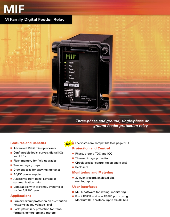
GE Multilin MIF series digital feeder relay
MIF-P type: three-phase+grounding protection relay, suitable for comprehensive protection of three-phase distribution circuits;
MIF-N type: single-phase or ground protection relay, focusing on single-phase circuit or ground fault special protection.
GE Multilin MIF series digital feeder relay
Product basic positioning and core applications
1. Product type and positioning
The MIF series belongs to the M Family (M series) digital feeder relay, which is divided into two core models according to the protected object:
MIF-P type: three-phase+grounding protection relay, suitable for comprehensive protection of three-phase distribution circuits;
MIF-N type: single-phase or ground protection relay, focusing on single-phase circuit or ground fault special protection.
2. Core application scenarios
Main protection: Main circuit protection for various voltage levels of distribution networks, covering lines, distribution equipment, etc;
Backup/auxiliary protection: Backup protection for transformers, generators, and motors to compensate for blind spots in main protection;
Control and Monitoring: Cooperate with circuit breakers to achieve remote control, while providing electrical parameter measurement and equipment status monitoring.
Core functions and technical features
1. Protection function (core highlight)
The MIF series focuses on "overcurrent protection" and is equipped with various specialized protections to adapt to different fault scenarios
(1) Overcurrent protection (TOC/IOC)
Protection type applicable model key parameters and characteristics
Phase TOC MIF-P (three-phase), MIF-N (single-phase) - Setting range: 0.1-2.4 times rated current (I n)
-Curve selection: 4 standard curves (corresponding to ANSI/IEC)+1 user-defined curve, supporting time multiplier adjustment
-ANSI corresponds to IEC curves: Normal Inverse Time (ANSI) → IEC A, Extraordinary Inverse Time → IEC B, Extreme Inverse Time → IEC C, Timed Limit → Timed Limit
Ground TOC MIF-P (standard), MIF-N (optional) - Curve and parameter settings for in-phase overcurrent protection
-Grounding signal acquisition: By default, the residual current of three-phase CT is summed up (without the need for additional sensors); Sensitive scenes can be paired with zero sequence grounded CT (surrounding three-phase conductors) to improve detection accuracy
Instantaneous Overcurrent (IOC) Full Model - Independent Configuration: MIF-P includes 2 sets of three-phase IOC+2 sets of grounded IOC, MIF-N includes 2 sets of single-phase/grounded IOC
-Setting range: pickup (0.1-30 times I n), delay (0-100 seconds), supports individual enable/disable
(2) Other special protections
Thermal Image Protection: prevents equipment from being damaged due to overload and overheating, with a constant heating time
T1 (adjustable from 3-600 minutes), cooling time constant T2 (adjustable from 1-6 times T1), suitable for different device heat dissipation characteristics;
Cold Load Pickup (optional): Automatically adjust the overcurrent setting value when powering on again to avoid triggering the protection by overload current;
Breaker Failure Protection (optional): The basic function is to detect that the circuit breaker has not been opened; Complex solutions can be implemented through digital inputs and configurable output logic (logic gates, timers);
Breaker Health Monitoring (optional): Users set a cumulative current threshold, triggering an alarm when the threshold is exceeded, achieving "on-demand maintenance".
2. Control and operation functions
Circuit breaker control: supports circuit breaker opening/closing operations, triggered by programmed output terminals, and verified by digital input terminals to ensure successful operation;
Two Settings Groups: Two sets of protection parameters can be pre-set to adapt to different operating conditions (such as normal load/peak load);
On site upgrade: Designed with Flash Memory, it supports firmware upgrade through communication or software on-site, without the need to disassemble the device.
3. Monitoring and metering functions
Event recording: Store 32 event records, record key events such as faults and operations, for easy fault tracing;
Waveform recording: supports analog/digital waveform recording, captures instantaneous changes in electrical parameters during faults, and assists in fault analysis;
Dual end metering: CT transformation ratio can be set, and the primary and secondary current measurement values can be monitored simultaneously to meet the data requirements of operation and maintenance.
4. Hardware and interface characteristics
Power adaptation: Supports AC/DC universal power supply, covering 24-48V DC/AC, 110-250V DC, 110-230V AC (specific range see ordering parameters);
Communication interface: Front end RS232 port (local debugging), back-end RS485 port (remote communication), both support ModBus ® RTU protocol, with a maximum speed of 19200 bps;
I/O configuration: comes standard with 2 digital inputs and 6 relay outputs (4 programmable), and can customize output logic (OR/NOT combination) through M+PC software;
Mechanical structure: Drawout case for easy maintenance; Compatible with M-series 19 inch half rack/full rack installation, compatible with system integration.
5. Software and user interaction
Configuration software: supports M+PC software (parameter settings, status monitoring), enerVista.com platform (remote management, see page 275 of the document for details);
Local operation: Front panel buttons for direct parameter adjustment and status viewing;
Indicator lights (LEDs): LED indicator lights can be configured to visually display the device's operating status and fault type.
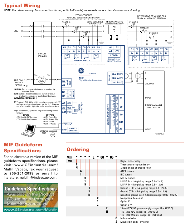
Wiring and safety regulations
1. Typical wiring reference
Grounding detection wiring: Two options are available - ① Three phase CT residual current summation (no additional sensors required); ② Zero sequence grounding CT (sensitive detection scenario);
Current input: It is recommended to use a 14 AWG (2.5mm ²) wire, and the terminal should be a fork or ring terminal;
Safe grounding: It is necessary to connect to a safe ground. Terminals B12, A12, and B11 are only for connecting SELV (safety extra low voltage) components (such as PLC), and withstand voltage testing is prohibited.
2. Safety Tips
Overvoltage category: Class II, suitable disconnect devices (switches or circuit breakers) need to be installed near the relay;
Internal fuse: The power circuit is equipped with a 1A/250V fast fuse to protect the equipment in case of malfunction.
Ordering information (model coding rules)
The MIF series model code format is * * MIF * * * * E * 00 * 00 * * *, and the meanings of the characters in each position are as follows, which need to be combined according to actual needs:
Encoding Position Optional Character Meaning Explanation
1st to 3rd digit MIF product identification (digital feeder relay)
The 4th P/N P=three-phase+grounding relay; N=single-phase or grounded relay
5th A/I A=ANSI standard curve; I=IEC standard curve
6th position 0/1/5=MIF-N type; 1=MIF-P type (I n=1A, setting range 0.1-2.4A); 5=MIF-P type (I n=5A, setting range 0.5-12A)
7th position 1/5/N grounding CT rated current: 1=1A (0.1-2.4A); 5=5A(0.5-12A); N=sensitive grounding (1A, 0.005-0.12A)
8th position (empty)/1/2 empty=base model (no options); 1=Option 1 (configurable I/O, event logging, recording); 2=Option 2 (including option 1 function+cold load input, circuit breaker failure/health monitoring, configurable logic)
The power specifications for positions 9-10 are 24-48V DC/AC (19-58V DC); 110-250V DC(88-300V DC); 110-230V AC(88-264V AC)
The installation method for positions 11-12 is empty=independent relay; M+=Installed on M+system (requires additional order of M050 half 19 inch rack or M100 full 19 inch rack, provided free of charge according to the number of relays)
Example
MIF P A 1 1 2 110: Three phase+grounding relay (P), ANSI curve (A), phase CT I n=1A (1), grounding CT I n=1A (1), including option 2 function (2), 110-250V DC power supply (110).
- YOKOGAWA
- Reliance
- ADVANCED
- SEW
- ProSoft
- WATLOW
- Kongsberg
- FANUC
- VSD
- DCS
- PLC
- man-machine
- Covid-19
- Energy and Gender
- Energy Access
- Renewable Integration
- Energy Subsidies
- Energy and Water
- Net zero emission
- Energy Security
- Critical Minerals
- A-B
- petroleum
- Mine scale
- Sewage treatment
- cement
- architecture
- Industrial information
- New energy
- Automobile market
- electricity
- Construction site
- HIMA
- ABB
- Rockwell
- Schneider Modicon
- Siemens
- xYCOM
- Yaskawa
- Woodward
- BOSCH Rexroth
- MOOG
- General Electric
- American NI
- Rolls-Royce
- CTI
- Honeywell
- EMERSON
- MAN
- GE
- TRICONEX
- Control Wave
- ALSTOM
- AMAT
- STUDER
- KONGSBERG
- MOTOROLA
- DANAHER MOTION
- Bentley
- Galil
- EATON
- MOLEX
- Triconex
- DEIF
- B&W
- ZYGO
- Aerotech
- DANFOSS
- KOLLMORGEN
- Beijer
- Endress+Hauser
- schneider
- Foxboro
- KB
- REXROTH
- YAMAHA
- Johnson
- Westinghouse
- WAGO
- TOSHIBA
- TEKTRONIX
- BENDER
- BMCM
- SMC
- HITACHI
- HIRSCHMANN
- XP POWER
- Baldor
- Meggitt
- SHINKAWA
- Other Brands
- UniOP
- KUKA
- IBA
- Beckhoff
- ADLINK
-
ADLINK HPCI-14S12U - Industrial Control Backplane 12PCI Backplane PCI-14S Passive Backplane
-
ADLINK PCIe-GIE74C - image acquisition card 4-CH GigE Vision PoE+ Frame Grabber
-
ADLINK PCI-8164 - control card 4-Axis Advanced Motion Controller Board
-
ADLINK PCIe-U304 - 4 Port USB3 PCIe Frame Grabbers USB Screw Hole Card
-
ADLINK PCI-9112 - Multi-Function Data Acquisition Card DAQ Card
-
ADLINK PCI-7432 - 51-12013-0A50 4-CH Isolated Numérique I/O PCI Cartes Digital I/O Card
-
ADLINK PCA-6106P3-0C1 REV.C1 - backplane 6-Slot Passive Backplane Board
-
ADLINK PCI-7224 - 24-CH Opto-Isolated Digital I/O PCI Board
-
ADLINK CPCI-7433R(G) - Digital Input Board Rear I/O CompactPCI Card
-
ADLINK EBP-13E4 - 51-46703-0A30 Industrial PC Backplane Passive Backplane
-
ADLINK PCIE-HDV62 - Image acquisition card High Definition Video Frame Grabber
-
ADLINK EBP-13E4 - 51-46703-0A30 Industrial Backplane Board Passive Backplane
-
ADLINK 90111-B1 / CPCI-6770 - PCB CPU MODULE CompactPCI Single Board Computer
-
ADLINK PCI-7248 - DATA ACQUISITION PCI CARD 48-CH Parallel Digital I/O Board
-
ADLINK PCI-7230 - 51-12003-0a50 board PCI7230 32-CH Isolated Digital I/O Card
-
ADLINK PCI2A000CB - 51-20000-0B30 Multi-Function DAQ Card Baseboard
-
ADLINK PCI-8134-005 - 4-Axis Motion Controller Card
-
ADLINK PCI-7224 - 24-CH Opto-Isolated Digital I/O PCI Card
-
ADLINK PCI-7434 - 64-CH Isolated Digital Output Card
-
ADLINK PCI-8132 - motion control card 2-Axis Servo & Stepper Controller
-
ADLINK PCI-8134 - Motion Controller PCI Card 4-Axis Controller Board
-
ADLINK PCI-8164 - Motion Control Card 51-12406-0A40 4-Axis Controller
-
ADLINK 51-12001-0C20 - Circuit Board Data Acquisition Interface Module Hardware
-
ADLINK NuPR0-840 - industrial control motherboard Full-Size PICMG CPU Board
-
ADLINK PCI-7444 - 51-12023-0A10 card 128-CH Isolated Digital Output Board
-
ADLINK PCI-1612B - data acquisition card 4-Port RS-232/422/485 Serial Communication Card
-
ADLINK PCI-6208V 009 - 8/16-CH 16-Bit Analog Output Cards PCB-I-E-482=6BX3
-
ADLINK NUPRO-935A/LV - industrial control motherboard Full-Size PICMG SBC Board
-
ADLINK PCI-9114DG - Multi-Function DAQ Card Data Acquisition PCI Card
-
ADLINK ACL-7130 - Data acquisition card Isolated Digital I/O Board
-
ADLINK ABX-6300D-4E1-BP - board ABX6300D4E1BP Video Interface Expansion Card
-
ADLINK CPCI-6940 - CPCI-6940/D1539/M16-0(EA)-000E 6U CompactPCI Processor Board
-
ADLINK NuPRO-760 - industrial control motherboard Half-Size PICMG SBC CPU Board
-
ADLINK IMB-M42H (G)-0020 - industrial control motherboard LGA1155 Micro-ATX Mainboard
-
ADLINK RTV-24 / PCI-MP4S - 51-12519-1C30 4-Channel Real Time Video Capture Board
-
ADLINK PCI-8134 - 4-Axis Servo & Stepper Motion Controller Card
-
ADLINK MXC-6101D - V.PC000.002.ST.00 Box PC Configurable Embedded Computer
-
ADLINK PCI-8134A - 51-12421-0A10 Motion Control Card 4-Axis Controller Card
-
ADLINK DIN-100S / DIN-100SA1 - Technology SCSI-II TB 100-PIN Terminal Block Board
-
ADLINK DIN-812M001 / DIN812M001 - 51-14034-0A1 51140340A1 Terminal Module Breakout Interface
-
ADLINK PCI-8164 - Servo motion control 4-Axis Advanced Controller Card
-
ADLINK PCIe-GIE64 - Acquisition card GigE Vision PoE+ Frame Grabber
-
ADLINK M-302 - Industrial control motherboard ATX PC Board Mainboard
-
ADLINK PCI-8134 - Motion Controller PCI Card 4-Axis Controller Board
-
ADLINK PCI-RTV24 - Image capture card Analog Video Frame Grabber
-
ADLINK PCI-8102 - Motion control card 2-Axis Servo & Stepper Controller Board
-
ADLINK PCI-9112 REV.B1 - Card Multi-Function Data Acquisition Card
-
ADLINK HSI-DI32-M-N / HSL-TB32-M-DIN - Discrete I/O MODULE Distributed Automation Module System
-
ADLINK PCI-7296 - IO card REV.A3 96-CH Parallel Digital I/O Card
-
ADLINK DIN-814P-A4 / 814Y - terminal board Motion Control Interface Block
-
ADLINK DIN-814P-A4 - 51-14056-0A10 PCB-I-E-2736=ZA01 Screw Terminal Board Breakout
-
ADLINK M-322 - motherboard Industrial Control Computer Mainboard
-
ADLINK NUPRO-406 REV:B1 - industrial control motherboard Full-Size PICMG CPU Board
-
ADLINK AMP-204C - card DSP-Based 4-Axis Advanced Pulse-Train Controller
-
ADLINK HPCI14S REV.B1 - industrial computer baseboard 14-Slot Passive Backplane
-
ADLINK PCI-7250 - 8-CH Relay Output & 8-CH Isolated DI PCI Card
-
ADLINK EBP-13E2 - baseplate Passive Backplane Industrial Computer Chassis Board
-
ADLINK LPCI-3488A - PCI-GPIB card 51-12801-0A30 acquisition card IEEE-488 Interface Board
-
ADLINK PCI-6216V-GL - 51-12201-0C30 16-CH 16-Bit Voltage Analog Output Card
-
ADLINK ACL-8454 - 16-CH Isolated Digital I/O & 4-CH Counter Card
-
ADLINK HPCI-9S7U - backplane Passive Backplane Compatible with NuPRO-A301 852 841 842
-
ADLINK DAQ-2010-007 - Simultaneous-Sampling Multi-Function Data Acquisition Card
-
ADLINK MP-C154 - 51-64205-0A10 Motion Control Card 4-Axis Controller Board
-
ADLINK MXE-202/mSSD16B/WiFi-BT - Matrix Rugged I/O Platform Embedded Fanless Computer
-
ADLINK CM-920-R-17 - PC/104-Plus Single Board Computer Module Intel Celeron M
-
ADLINK PCI-7250 NSMP - 8-CH Relay Output & 8-CH Isolated DI Card
-
ADLINK PCI-8164 - 4-Axis Motion Controller PCI Card W/ Cable and Breakout Box
-
ADLINK EMX-100 - Ethernet-based 4-axis Motion Controllers Distributed Motion Module
-
ADLINK PCI-8134A - Press control card 4-Axis Motion Controller Board
-
ADLINK M-845EG REV:3.2 - industrial motherboard Pentium 4 Socket 478 Micro-ATX
-
ADLINK PCI-9114A Rev A2 DG - card High-Resolution Multi-Function Data Acquisition Board
-
ADLINK IEC-915GV - REV 1.1 Industrial motherboard Socket 478 CPU Board
-
ADLINK PCI-9111DG(G) - Data Acquisition Card Multi-Function DAQ Card
-
ADLINK HPCI-15S10 REV:B2 - Industrial computer base plate Passive Backplane Board
-
ADLINK NuPR0-840 / NuPR0-840DV - industrial control motherboard Full-size PICMG CPU Board
-
ADLINK RTV-24 / PCI-MP4S - 51-12519-1C30 4-Channel Real Time Video Capture Board
-
ADLINK NUPRO-780 - industrial control motherboard Pentium III Single Board Computer
-
ADLINK PCI-7296 - 0050 card 96-CH Opto-Isolated Parallel DIO Card Set
-
ADLINK NUPRO-780 - industrial control motherboard PICMG Full-Size SBC
-
ADLINK PCI-7248 - 51-12006-0A3 002 Pci 7248 48-CH Parallel Digital I/O Card
-
ADLINK PCI-7230 - 32-CH Isolated Digital I/O Card
-
ADLINK AMP-204C - motion control card 4-Axis Advanced Controller Board
-
ADLINK PCI-1714UL - Card Ultra High-Speed 4-CH Simultaneous Sampling DAQ
-
ADLINK NuPRO-E330 - industrial computer equipment motherboard PICMG 1.3 SHB SBC
-
ADLINK AMP-204C - DSP-Based 4-Axis Advanced Pulse-Train Motion Controller Module
-
ADLINK PCI-7256 - 001 51-12206-0A2 REV.A2 LPCI-7256 16-CH Latching Relay Output Card
-
ADLINK ND6050 - NUDAM DIGITAL I/0 MODULE Distributed I/O Unit
-
ASEM BM100 - Box PC Embedded Fanless Industrial Computer
-
ADLINK PCI-7250 - PCI Acquisition Card 8-CH Relay Output & Isolated DI Board
-
ADLINK PCI-8164 - Servo motion control 4-Axis Controller Card
-
ADLINK NuPRO-A40H - Industrial Motherboard 51-41807-1A30 OSP LGA1155 H61
-
ADLINK ADMAX X300 SERVER - 51066010-0A30 motherboard Multi-Processor Mainboard
-
ADLINK CMe-GIE62+ - 51-32903-0A30 control card PC/104-Plus GigE Vision Frame Grabber
-
ADLINK NUPRO-780 - industrial control motherboard Full-Size PICMG SBC CPU Board
-
ADLINK ETX-AT-N270-18/GKTEL - 51-71111-OB10 motherboard ETX CPU Module Board
-
ADLINK DIN-812M - interface module Terminal Block Connection Board
-
ADLINK IMB-M42H - industrial control motherboard LGA1155 Micro-ATX Mainboard
-
ADLINK PXIS-2508 - 8-slot 3U PXI Instrument Chassis Power Hardware Assembly
-
ADLINK AMP-208C - Motion Control card DSP-Based 8-Axis Pulse-Train Controller
-
ADLINK PCI-9111 / PCI-9111DG - Multi-Function Data Acquisition Card DAQ Board
-
ADLINK IEEE-488 GPIB card - Bus Interface Controller Communication Board
-
ADLINK RTV-24 - 51-12519-1C30 image acquisition card Video Frame Grabber Card
-
ADLINK TB-24P/24-01 - Board 24 Way Screw Terminal Breakout Board
-
ADLINK HSL-DI16DO16-DB-NN - 51-23015-0A40 Distributed Discrete I/O Module Set
-
ADLINK PCI-7442 - switch quantity card data acquisition card 64-CH Isolated Card
-
ADLINK ACL-7130 REV. B2 - industrial control capture card Isolated Digital I/O PCI Card
-
ADLINK PCI-6S / PCI6S - Backplane 6-Slot Passive Backplane Chassis Board
-
ADLINK ACL-8113A - card Isolated Digital Input Card
-
ADLINK CPCI-6208V-003 - board cPCI CompactPCI 8-CH Analog Output Card
-
ADLINK DIN-100S-01(G) - SCSI 100-Pin Terminal Block Interface Board
-
ADLINK PCI-7433 - Isolated Digital Input Card 64-CH
-
ADLINK PCI-9812 - Synchronous sampling analog input card High-Speed DAQ Board
-
ADLINK PCI-7434 REV.B1 - PLOTECH PCB-I-E-1182=6EX2 64-CH Isolated Digital Output Card
-
ADLINK PCIe-RTV24 - 51-18016-0A20 4-CH Real-Time Video Capture Card PCIe Frame Grabber
-
ADLINK PCI-8144 / PCI-8144N - Motion control card 4-Axis Stepper Motor Controller
-
ADLINK DIN-68S-01 - terminal board 68-Pin Connector Terminal Block
-
ADLINK MP-C154 - Motion control card 4-Axis Advanced Controller Card
-
ADLINK PCI-7248 (G) - Motherboard 48-CH Parallel Digital I/O Card
-
ADLINK MXE-1301(G) - Intel Atom D2550+NM10 MXE 1300 Series 93-4130-0030 Embedded Computer
-
ADLINK PRO-841 Rev 2.0 / PRO-060907000670 - CPU 2.26GHz & RAM Industrial PC Board
-
ADLINK NuPRO-E330 - Industrial Motherboard System Host Board PICMG 1.3 SHB
-
ADLINK EBP-13E2 - Passive Backplane Industrial Chassis Baseboard
-
ADLINK PCI-8154 - 4-axis Motion Control Card Servo & Stepper Controller Board
-
ADLINK NuPrO-596 REV.B1 - industrial control motherboard Half-size PICMG CPU Board
-
ADLINK PCI-7852 / PCI-7851 - PLOTECH High-Speed Link Control Card Interface Board
-
ADLINK PCI-9112 - 51-12252-0D20 data acquisition card Multi-Function DAQ
-
ADLINK PCI-9112 - Circuit Board 51-12252-0C20 Multi-Function Data Acquisition Card
-
ADLINK NUPRO-761 REV:1.1 - industrial control motherboard PICMG Full-Size CPU Board

K-JIANG

Add: Jimei North Road, Jimei District, Xiamen, Fujian, China
Tell:+86-15305925923