
K-WANG


Watlow MLS300 Series Controller
Watlow MLS300 Series Controller
Product basic positioning and core features
1. Product positioning
The MLS300 series is a multi loop PID controller, available in two versions: 16 loop (MLS316) and 32 loop (MLS332), supporting thermocouples RTD、 Multiple sensor inputs such as linear voltage/current and pulse can achieve independent or linked control of process parameters such as temperature, pressure, and flow rate. The system adopts a modular design, compatible with multiple expansion modules (such as DAC/SDAC analog output modules), supports EIA/TIA-232/485 serial communication, can be connected to upper computer or PLC systems, and complies with CE and UL standards ®/ C-UL ® Certification and EU EMC Directive (EN 61326).
2. Core advantages
Advantages Category Specific Characteristics Value Explanation
Multi loop control single device supports 16/32 independent PID loops, each loop can be configured with heating/cooling dual outputs to reduce the number of devices, reduce panel space occupation, and adapt to multi zone process scenarios (such as multi-stage extruders and large ovens)
Flexible input compatibility supports J/K/T/S/R/B/E type thermocouples, 100 Ω platinum RTD (2/3 wire system), 0-20mA/4-20mA current, 0-12V voltage, and pulse input (up to 2kHz) to reduce spare parts inventory and adapt to sensor requirements of different processes without the need for additional signal conversion modules
Advanced control function supports cascade control, proportional control, remote simulation set point, and differential control (enhanced firmware); Ramp/Soak batch control (optional firmware) to meet complex process requirements (such as temperature pressure linkage in chemical reaction vessels, staged temperature control for material aging testing)
High reliability built-in sensor fault detection (open circuit/short circuit/reverse connection), power failure protection, CPU watchdog; Supports storing and calling 8 job programs to shorten troubleshooting time, avoid process abnormalities, and adapt to switching between multiple varieties and small batch production
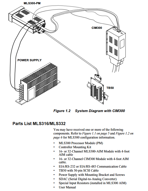
System composition and hardware architecture
1. List of core components
Component Name, Model/Specification, Function and Function
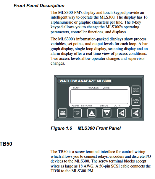
Processor module (PM) MLS300-PM system core, including CPU, 2-line 16 character fluorescent display screen, 8-key keyboard, responsible for data calculation, loop control, and communication management
The Analog Input Module (AIM) MLS300-AIM-16 (16 channels)/AIM-32 (32 channels) receives sensor signals, completes signal conditioning and A/D conversion, and communicates with the processor module through RJ45 cables
Compact Input Module (CIM) CIM316 (16 channels)/CIM332 (32 channels) high-density input module, using D-Sub 50 connector to reduce installation space and adapt to high integration scenarios
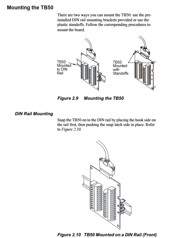
Terminal board (TB50) MLS300-TB50 50 50 pin SCSI interface terminal board, used for digital I/O, power and control output wiring, supports DIN rail or bracket installation
Expansion Module - DAC (Digital to Analog Converter): 2-channel configurable 4-20mA/0-5V/0-10V output
-SDAC (Serial Digital to Analog Converter): 1 high-precision analog output, supporting process variable retransmission to convert digital output to analog signal, suitable for analog control equipment such as valves and frequency converters
The MLS300-PS power module inputs 120/240V AC and outputs 15V DC/1.2A and 5V DC/4A, providing isolated power supply for the system
2. Hardware architecture logic
The system adopts a "master-slave" communication architecture, and the data flow is as follows:
Perception layer: Sensors (thermocouples/RTDs, etc.) transmit process signals to the AIM/CIM module, completing signal conditioning and A/D conversion;
Control layer: The processor module (PM) receives digital signals from AIM/CIM, generates control instructions through PID algorithm, and sends them to the TB50 terminal board;
Execution layer: TB50 transmits instructions to actuators such as solid-state relays (SSRs) and contactors to control heating/cooling equipment;
Monitoring layer: Implement parameter settings, status monitoring, and alarm processing through the front-end panel or upper computer (such as WatView software).
Key technical parameters
1. Input parameters
(1) Sensor support and accuracy
Input Type Range Accuracy (25 ℃ environment) Remarks
Thermocouple (Type J) -212~760 ℃ (-350~1400 ℉) ± 1.1 ℃ with cold end compensation, linearization, and open/short/reverse detection
Thermocouple (Type K) -268~1371 ℃ (-450~2500 ℉) ± 1.3 ℃-
RTD1 (high precision) -100~275 ℃ (-148~527 ℉) ± 0.35 ℃ (25 ℃) 0.1 ℃ resolution, only supported by MLS304/308
RTD2 (Wide Range) -120~840 ℃ (-184~1544 ℉) ± 0.9 ℃ (25 ℃) 1 ℃ resolution, only supported by MLS304/308
Linear current 0-20mA/4-20mA ± 0.03% full range requires external scaling resistor
Linear voltage 0-5V/0-10V/0-12V ± 0.03% full-scale-
Pulse input 0-2kHz resolution 0.006% used for encoder speed measurement (such as conveyor belt speed control)
(2) Input performance
Sampling rate: MLS316 is 1.5 times/second (60Hz), MLS332 is 0.75 times/second (60Hz);
Noise suppression: Common mode rejection ratio (CMR)>85dB at 60Hz, input filtering configurable (0-255 scan period);
Temperature coefficient: 40ppm/℃, ensuring measurement stability in a wide temperature environment.
2. Output and communication parameters
Parameter category specification value precautions
Digital output with 34 open collector outputs, each with a maximum sink current of 60mA (5V DC). The onboard power supply provides a total current of 350mA for controlling SSR, alarm indicator lights, etc. It can be configured as a control output or alarm output
Analog output without onboard analog output, needs to be expanded through DAC/SDAC module:
-DAC: 2-channel 4-20mA/0-5V/0-10V, accuracy ± 0.75%
-SDAC: 1 high-precision output with an accuracy of ± 0.05%. Full scale SDAC supports process variable retransmission and is suitable for scenarios that require high-precision analog signals (such as PLC analog inputs)
Serial communication interface: EIA/TIA-232 (single device, maximum 50m), EIA/TIA-485 (multi device, maximum 4000ft);
Baud rate: 2400/9600/19200bps;
Protocol: Modbus RTU, Anafaze protocol, Allen Bradley PLC/2 compatible protocol EIA/TIA-485 supports networking of 32 devices and requires 200 Ω terminal resistors to be configured at both ends of the bus
Power requirements: Processor module: 12-24V DC ± 15%, maximum 1A;
AIM/CIM module: 5V DC (provided by the processor module). It is recommended to use an isolated power supply to avoid sharing the circuit with high-power devices and reduce interference
Installation and wiring specifications
1. Pre installation requirements
Environmental conditions: working temperature 0-50 ℃, storage temperature -20-60 ℃, relative humidity 10% -95% (no condensation); Keep away from strong electromagnetic interference sources (such as frequency converters and high-voltage cables) and avoid vibration (amplitude ≤ 0.5mm, frequency ≤ 50Hz).
Qualification requirements: Installation personnel must have industrial electrical installation qualifications, and high-voltage wiring (such as power module input) must be operated by certified electricians; Prepare torque wrenches (0.5-0.6Nm), shielded cables, crimping tools, etc.
Space requirements: A 1.96 × 3.78-inch (50 × 96mm) opening should be reserved for the installation of the processor module panel, and a wiring space of ≥ 7.4 inches (188mm) should be reserved on the back; The AIM module requires a reserved installation space of 6.5 x 5 x 5.75 inches (165 x 127 x 146mm).
2. Installation steps of core components
(1) Processor module (MLS300-PM)
Cut 1.8 × 3.63 inch (46 × 92mm) openings on the panel, remove module brackets and baffles;
Insert the module into the opening, fit the installation ring on the back, fix the upper and lower brackets, and tighten the screws (torque 0.5Nm);
Connect the AIM/CIM communication cable (RJ45 interface, labeled "To AIM"), TB50 50 50 pin SCSI cable, and power supply (TB1 terminal:+V to 12-24V DC, COM to negative pole).
(2) Input module (AIM/CIM)
AIM module:
Fix the AIM-TB terminal board with 4 # 6 screws to ensure grounding (grounding resistance ≤ 4 Ω);
Connect sensor cables: thermocouple "+" is connected to A+, "-" is connected to A -; RTD 3-wire system requires the "common end" to be connected to A COM, and the "signal end" to be connected to A+/A -;
Connect AIM to the processor module via RJ45 cable and test AIM power supply (TB3 terminal:+5 IN to PWR COM voltage 4.75-5.25V DC).
CIM module:
Support DIN rail or direct installation, connect sensors through D-Sub 50 connectors (J1 for 16 channels, J2 for 32 channel expansion);
Communication cable (RJ45) connected to CIM J3 interface, power supply (TB2 terminal: EX connected to processor EX, COM connected to processor COM).
(3) Terminal board (TB50)
Choose DIN rail or bracket installation, connect 50 pin SCSI cable to the processor module;
Wiring specifications:
Digital output (terminals 9-42): When controlling SSR, connect+5V to the positive pole of SSR and connect the output terminal to the negative pole of SSR;
Digital input (terminals 43-50): One end of the external switch is connected to the input terminal, and the other end is connected to CTRL COM (terminal 3/4);
Power terminal (1-2):+5V is the output (for SSR, etc.), CTRL COM is the common terminal, and grounding is prohibited.
3. Wiring and anti-interference requirements
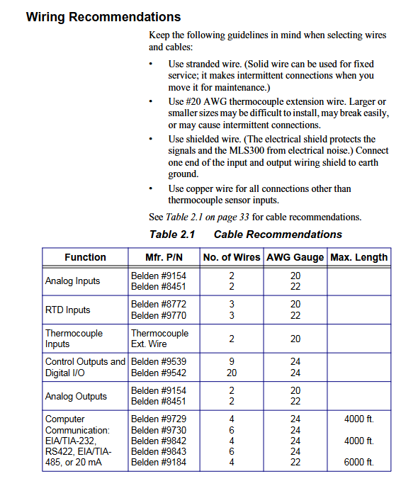
Recommended specifications for cable types and wiring requirements
Sensor cable thermocouple: 20AWG thermocouple extension wire; RTD: 22AWG shielded twisted pair cable; Linear signal: 22AWG shielded twisted pair cable should be kept away from high-voltage cables (≥ 10cm), and the shielding layer should be grounded at one end (processor end); RTD cable length ≤ 100m
Control the output cable with 24AWG multi-core shielded wire and separate it from the input cable to avoid parallel laying; SSR control line length ≤ 50m
Communication cable EIA/TIA-232: Belden 9729 (6-core shielded wire, ≤ 50m); EIA/TIA-485: Shielded 9843 (4-core shielded twisted pair, ≤ 1200m) with both ends of the shielding layer grounded; The EIA/TIA-485 bus requires a 200 Ω terminal resistor to be configured at both ends
Basic Operations and Configuration
1. Startup and initialization
After confirming that the wiring is correct, turn on the power and the processor module display screen will light up. After about 1 second, it will enter the "bar chart display" (default display shows 8 circuit statuses);
If an "AIM COMM FAIL" alarm occurs, it is necessary to check whether the AIM/CIM communication cable is securely plugged in and whether the power supply is normal;
The first startup requires the execution of the "NO key reset" (press and hold the NO key in the power-off state, press YES to confirm after powering on), and restore the factory default parameters (skip when backing up the configuration in advance).
2. Core operations (front-end panel)
(1) Loop monitoring and parameter adjustment
Display switching:
Press the BACK key to switch between "Bar Chart Display" (8 circuit status), "Single Circuit Display" (Single Circuit PV/SP/Output%), and "Job Display" (Current Running Job);
Under single circuit display, press the YES/NO key to switch circuits, press the CHNG SP key to modify the set point (press YES/NO to adjust the value, press ENTER to confirm).
Control mode switching:
Press the MAN/AUTO key to switch between "AUTO" and "MAN" modes; In manual mode, adjust the output percentage (0-100%) according to YES/NO;
Press MAN/AUTO+ENTER to start "TUNE", and the controller will automatically calculate PID parameters (ensuring process stability and no severe disturbances).
(2) Alarm processing
When the alarm is triggered, the display screen automatically switches to the fault circuit, displaying the alarm code (such as "FS" for sensor fault, "HP" for high process alarm), and the buzzer is activated;
Press the ALARM ACK button to confirm the alarm. If there are multiple alarms, they need to be confirmed one by one; After troubleshooting, the alarm will automatically clear;
The global alarm output (terminal 8) is activated when any unconfirmed alarm occurs, and can be connected to an external alarm light or buzzer.
3. Basic parameter configuration (Setup menu)
Enter the Setup menu through the "three key combination" (ENTER → ALARM ACK → CHNG SP), and the core configuration items are as follows:
Menu Name Key Parameter Configuration Description
When communicating with multiple devices, a unique address (1-247) must be set for the SETUP GLOBAL ParameterS controller address, communication baud rate, and power on output status; The baud rate needs to be consistent with the upper computer (default 19200bps)
SETUP LOOP INPUT input type, unit, filter coefficient selection corresponding to sensor type (such as "J T/C" and "RTD1"); Input filtering (0-255 scan) is used to suppress noise
SETUP LOOP Control PARAMS heating/cooling PID parameters (PB/TI/TD), the smaller the output filter PB (proportional band), the higher the gain; The longer the TI (integration time), the stronger the ability to eliminate steady-state errors; TD (Differential Time) is used to suppress overshoot
SETUP LOOP OUTPUTS heating/cooling output enable, output type, sensor fault output type optional "TP (time ratio)" "DZC (distributed zero crossing)" "SDAC"; When the sensor fails, the output can be set to 0% (default) or a custom value
SETUP LOOP ALARMS high/low process alarm, deviation alarm, alarm dead zone high process alarm set point needs to be higher than the process upper limit; Set the deviation alarm to SP ± 5% (to avoid frequent alarms); Set the dead zone to 2-5 (unit consistent with PV)
Advanced features (firmware optional)
1. Enhanced Features firmware
(1) Cascade Control
Application scenario: Suitable for processes with "primary secondary" variables (such as reactor temperature jacket temperature control), where the main circuit output serves as the secondary circuit set point;
Configuration steps:
Enter the SETUP LOOP CASCADE menu and select "PRIM. LOOP" (such as reactor temperature loop 1);
Set the "Base SP", "Minimum/Maximum Set Point", and "Heating/Cooling Span (HT/CL SPAN)" to define the magnitude of the impact of the main circuit output on the secondary circuit set point;
The secondary circuit (jacket temperature circuit 2) needs to enable the "cascade mode" to ensure that the sampling period of the main and secondary circuits matches.
(2) Ratio Control
Application scenario: Suitable for processes that require proportional control (such as KOH solution dilution, water flow KOH flow 1:2);
Configuration steps:
Enter the SETUP LOOP RATIO CON menu and select "MSTR LOOP" (water flow circuit 1);
Set "CTRL RATIO" (e.g. 0.5, KOH flow=water flow x 0.5), "SP DIFF" (compensating deviation, default 0);
The proportional circuit (KOH flow circuit 2) automatically follows the changes in the main circuit PV and maintains the set ratio.
2. Slope - Insulation Fasteners (Ramp/Soak)
Application scenario: staged temperature control process (such as material annealing: heating → insulation → cooling), supporting 17 profiles, each profile containing 20 segments;
Core functions:
Ramp: Rise from the current SP to the target SP within a set time (e.g. 10 ℃/min to 200 ℃);
Soak: Maintain the target SP setting time (such as holding at 200 ℃ for 60 minutes);
Trigger and Event: Each segment can be configured with 2 digital trigger inputs (such as external signal activation) and 4 event outputs (such as initiating agitation);
Configuration steps:
Enter the SETUP RAMP/SOAK PROFILE menu, select Profile (A-Q), and set the "Time Reference" (HH: MM/MM: SS);
Edit Segment: Set "Segment Time", "Target SP", "TOLERANCE" (if ± 2 ℃, pause timing if exceeded);
Assign Profile to the target circuit, press the RAM/SOAK key to start, and the display screen will show the remaining time and current segment number in real time.
Troubleshooting and Maintenance
1. Common fault handling
Possible causes and solutions for the fault phenomenon
The display screen is not properly connected to the power supply, and the processor module is faulty. Check the TB1 terminal voltage (12-24V DC); Replace the processor module for testing
Abnormal sensor readings (high/low), incorrect sensor wiring, incorrect input type configuration, interference confirmation of thermoelectric dipole/RTD wiring; Check the "Input Type" in the Setup menu; Check the grounding of cable shielding
No response output enabled, SSR fault, loose TB50 wiring entering SETUP LOOP OUTPUTS confirmation output enabled; Measure the voltage at the SSR control terminal (conducting at 5V DC); Re tighten the terminal screws
Communication failure address/baud rate mismatch, cable failure, EIA/TIA-485 terminal resistance not connected, check the communication parameters between the controller and the upper computer; Use a multimeter to test the continuity of communication cables; Connect a 200 Ω resistor at the beginning and end of the bus
Alarm for "FS (sensor malfunction)" thermocouple open/short circuit, RTD disconnection, input module malfunction check sensor cable continuity; Replace the sensor for testing; Replace the AIM/CIM module for testing
2. Regular maintenance
Requirements for maintenance cycle operation content
Check the display screen daily for any errors and ensure that the alarm light is functioning properly; Do not wipe the display screen with alcohol when cleaning the panel and sensor; The sensor probe is free of oil stains/damage
Check the wiring terminals weekly for any looseness; Test the emergency stop and alarm function terminals and tighten the screw torque to 0.5-0.6Nm; confirm the ALARM ACK is valid after triggering the alarm
Monthly calibration of critical circuits (using standard signal sources to simulate sensor inputs); The calibration error of the cooling holes in the cleaning AIM/CIM module should be ≤ 0.1% of the full range; Compressed air blows away dust from the heat dissipation holes (pressure ≤ 0.3MPa)
Replace the processor module battery (CR2032, after power failure to avoid configuration loss) annually; Check that the battery replacement time for the shielding layer of the communication cable is ≤ 5 minutes; The shielding layer is undamaged and well grounded
Order
Ordering code rules (core position)
Code bit meaning optional values
Input module 16=AIM316 (16 channels), 32=AIM332 (32 channels) C1=CIM316、C2=CIM332 -
Firmware Type 1=Standard, 2=Extruder Specific, 3=Enhanced Features, 4=Ramp/Soak, C=Custom-
Terminal board 0=none, 1=18 pin terminal block, 2=50 pin terminal block (including 3-foot SCSI cable)-
Communication jumper 0=EIA/TIA-232, 1=EIA/TIA-485, 2=EIA/TIA-485 terminal matching-
- YOKOGAWA
- Reliance
- ADVANCED
- SEW
- ProSoft
- WATLOW
- Kongsberg
- FANUC
- VSD
- DCS
- PLC
- man-machine
- Covid-19
- Energy and Gender
- Energy Access
- Renewable Integration
- Energy Subsidies
- Energy and Water
- Net zero emission
- Energy Security
- Critical Minerals
- A-B
- petroleum
- Mine scale
- Sewage treatment
- cement
- architecture
- Industrial information
- New energy
- Automobile market
- electricity
- Construction site
- HIMA
- ABB
- Rockwell
- Schneider Modicon
- Siemens
- xYCOM
- Yaskawa
- Woodward
- BOSCH Rexroth
- MOOG
- General Electric
- American NI
- Rolls-Royce
- CTI
- Honeywell
- EMERSON
- MAN
- GE
- TRICONEX
- Control Wave
- ALSTOM
- AMAT
- STUDER
- KONGSBERG
- MOTOROLA
- DANAHER MOTION
- Bentley
- Galil
- EATON
- MOLEX
- Triconex
- DEIF
- B&W
- ZYGO
- Aerotech
- DANFOSS
- KOLLMORGEN
- Beijer
- Endress+Hauser
- schneider
- Foxboro
- KB
- REXROTH
- YAMAHA
- Johnson
- Westinghouse
- WAGO
- TOSHIBA
- TEKTRONIX
- BENDER
- BMCM
- SMC
- HITACHI
- HIRSCHMANN
- XP POWER
- Baldor
- Meggitt
- SHINKAWA
- Other Brands
- UniOP
- KUKA
- IBA
- Beckhoff
- ADLINK
-
ADLINK HPCI-14S12U - Industrial Control Backplane 12PCI Backplane PCI-14S Passive Backplane
-
ADLINK PCIe-GIE74C - image acquisition card 4-CH GigE Vision PoE+ Frame Grabber
-
ADLINK PCI-8164 - control card 4-Axis Advanced Motion Controller Board
-
ADLINK PCIe-U304 - 4 Port USB3 PCIe Frame Grabbers USB Screw Hole Card
-
ADLINK PCI-9112 - Multi-Function Data Acquisition Card DAQ Card
-
ADLINK PCI-7432 - 51-12013-0A50 4-CH Isolated Numérique I/O PCI Cartes Digital I/O Card
-
ADLINK PCA-6106P3-0C1 REV.C1 - backplane 6-Slot Passive Backplane Board
-
ADLINK PCI-7224 - 24-CH Opto-Isolated Digital I/O PCI Board
-
ADLINK CPCI-7433R(G) - Digital Input Board Rear I/O CompactPCI Card
-
ADLINK EBP-13E4 - 51-46703-0A30 Industrial PC Backplane Passive Backplane
-
ADLINK PCIE-HDV62 - Image acquisition card High Definition Video Frame Grabber
-
ADLINK EBP-13E4 - 51-46703-0A30 Industrial Backplane Board Passive Backplane
-
ADLINK 90111-B1 / CPCI-6770 - PCB CPU MODULE CompactPCI Single Board Computer
-
ADLINK PCI-7248 - DATA ACQUISITION PCI CARD 48-CH Parallel Digital I/O Board
-
ADLINK PCI-7230 - 51-12003-0a50 board PCI7230 32-CH Isolated Digital I/O Card
-
ADLINK PCI2A000CB - 51-20000-0B30 Multi-Function DAQ Card Baseboard
-
ADLINK PCI-8134-005 - 4-Axis Motion Controller Card
-
ADLINK PCI-7224 - 24-CH Opto-Isolated Digital I/O PCI Card
-
ADLINK PCI-7434 - 64-CH Isolated Digital Output Card
-
ADLINK PCI-8132 - motion control card 2-Axis Servo & Stepper Controller
-
ADLINK PCI-8134 - Motion Controller PCI Card 4-Axis Controller Board
-
ADLINK PCI-8164 - Motion Control Card 51-12406-0A40 4-Axis Controller
-
ADLINK 51-12001-0C20 - Circuit Board Data Acquisition Interface Module Hardware
-
ADLINK NuPR0-840 - industrial control motherboard Full-Size PICMG CPU Board
-
ADLINK PCI-7444 - 51-12023-0A10 card 128-CH Isolated Digital Output Board
-
ADLINK PCI-1612B - data acquisition card 4-Port RS-232/422/485 Serial Communication Card
-
ADLINK PCI-6208V 009 - 8/16-CH 16-Bit Analog Output Cards PCB-I-E-482=6BX3
-
ADLINK NUPRO-935A/LV - industrial control motherboard Full-Size PICMG SBC Board
-
ADLINK PCI-9114DG - Multi-Function DAQ Card Data Acquisition PCI Card
-
ADLINK ACL-7130 - Data acquisition card Isolated Digital I/O Board
-
ADLINK ABX-6300D-4E1-BP - board ABX6300D4E1BP Video Interface Expansion Card
-
ADLINK CPCI-6940 - CPCI-6940/D1539/M16-0(EA)-000E 6U CompactPCI Processor Board
-
ADLINK NuPRO-760 - industrial control motherboard Half-Size PICMG SBC CPU Board
-
ADLINK IMB-M42H (G)-0020 - industrial control motherboard LGA1155 Micro-ATX Mainboard
-
ADLINK RTV-24 / PCI-MP4S - 51-12519-1C30 4-Channel Real Time Video Capture Board
-
ADLINK PCI-8134 - 4-Axis Servo & Stepper Motion Controller Card
-
ADLINK MXC-6101D - V.PC000.002.ST.00 Box PC Configurable Embedded Computer
-
ADLINK PCI-8134A - 51-12421-0A10 Motion Control Card 4-Axis Controller Card
-
ADLINK DIN-100S / DIN-100SA1 - Technology SCSI-II TB 100-PIN Terminal Block Board
-
ADLINK DIN-812M001 / DIN812M001 - 51-14034-0A1 51140340A1 Terminal Module Breakout Interface
-
ADLINK PCI-8164 - Servo motion control 4-Axis Advanced Controller Card
-
ADLINK PCIe-GIE64 - Acquisition card GigE Vision PoE+ Frame Grabber
-
ADLINK M-302 - Industrial control motherboard ATX PC Board Mainboard
-
ADLINK PCI-8134 - Motion Controller PCI Card 4-Axis Controller Board
-
ADLINK PCI-RTV24 - Image capture card Analog Video Frame Grabber
-
ADLINK PCI-8102 - Motion control card 2-Axis Servo & Stepper Controller Board
-
ADLINK PCI-9112 REV.B1 - Card Multi-Function Data Acquisition Card
-
ADLINK HSI-DI32-M-N / HSL-TB32-M-DIN - Discrete I/O MODULE Distributed Automation Module System
-
ADLINK PCI-7296 - IO card REV.A3 96-CH Parallel Digital I/O Card
-
ADLINK DIN-814P-A4 / 814Y - terminal board Motion Control Interface Block
-
ADLINK DIN-814P-A4 - 51-14056-0A10 PCB-I-E-2736=ZA01 Screw Terminal Board Breakout
-
ADLINK M-322 - motherboard Industrial Control Computer Mainboard
-
ADLINK NUPRO-406 REV:B1 - industrial control motherboard Full-Size PICMG CPU Board
-
ADLINK AMP-204C - card DSP-Based 4-Axis Advanced Pulse-Train Controller
-
ADLINK HPCI14S REV.B1 - industrial computer baseboard 14-Slot Passive Backplane
-
ADLINK PCI-7250 - 8-CH Relay Output & 8-CH Isolated DI PCI Card
-
ADLINK EBP-13E2 - baseplate Passive Backplane Industrial Computer Chassis Board
-
ADLINK LPCI-3488A - PCI-GPIB card 51-12801-0A30 acquisition card IEEE-488 Interface Board
-
ADLINK PCI-6216V-GL - 51-12201-0C30 16-CH 16-Bit Voltage Analog Output Card
-
ADLINK ACL-8454 - 16-CH Isolated Digital I/O & 4-CH Counter Card
-
ADLINK HPCI-9S7U - backplane Passive Backplane Compatible with NuPRO-A301 852 841 842
-
ADLINK DAQ-2010-007 - Simultaneous-Sampling Multi-Function Data Acquisition Card
-
ADLINK MP-C154 - 51-64205-0A10 Motion Control Card 4-Axis Controller Board
-
ADLINK MXE-202/mSSD16B/WiFi-BT - Matrix Rugged I/O Platform Embedded Fanless Computer
-
ADLINK CM-920-R-17 - PC/104-Plus Single Board Computer Module Intel Celeron M
-
ADLINK PCI-7250 NSMP - 8-CH Relay Output & 8-CH Isolated DI Card
-
ADLINK PCI-8164 - 4-Axis Motion Controller PCI Card W/ Cable and Breakout Box
-
ADLINK EMX-100 - Ethernet-based 4-axis Motion Controllers Distributed Motion Module
-
ADLINK PCI-8134A - Press control card 4-Axis Motion Controller Board
-
ADLINK M-845EG REV:3.2 - industrial motherboard Pentium 4 Socket 478 Micro-ATX
-
ADLINK PCI-9114A Rev A2 DG - card High-Resolution Multi-Function Data Acquisition Board
-
ADLINK IEC-915GV - REV 1.1 Industrial motherboard Socket 478 CPU Board
-
ADLINK PCI-9111DG(G) - Data Acquisition Card Multi-Function DAQ Card
-
ADLINK HPCI-15S10 REV:B2 - Industrial computer base plate Passive Backplane Board
-
ADLINK NuPR0-840 / NuPR0-840DV - industrial control motherboard Full-size PICMG CPU Board
-
ADLINK RTV-24 / PCI-MP4S - 51-12519-1C30 4-Channel Real Time Video Capture Board
-
ADLINK NUPRO-780 - industrial control motherboard Pentium III Single Board Computer
-
ADLINK PCI-7296 - 0050 card 96-CH Opto-Isolated Parallel DIO Card Set
-
ADLINK NUPRO-780 - industrial control motherboard PICMG Full-Size SBC
-
ADLINK PCI-7248 - 51-12006-0A3 002 Pci 7248 48-CH Parallel Digital I/O Card
-
ADLINK cPCI-6626 - 6U CompactPCI 2.0 Blades i7-2710QE PCB-I-E-2570=9N41
-
ADLINK MXC-6322D(G) - Industrial Fanless Computer
-
ADLINK cPCI-8168-004 - CompactPci NulPC Motion Control Board 51-36402-0A3
-
ADLINK CPCI-7300[G] - COMPACTPCI Digital I/O Card Data Acquisition
-
ADLINK CPCI-6626/2710/M4G - COMPACTPCI COMPUTER BOARD
-
ADLINK cPCI-8168-009 - cPCI NulPC Motion Control Board
-
ADLINK cPCI-6626/2710/M4G - VME CPU Board Computer Board
-
ADLINK CPCI-R6200(G)-0040 - COMPACTPCI CONTROL BOARD
-
ADLINK CPCI-3840/PM18/M1G(G)-3650 - COMPACTPCI CPU Module Single Board Computer
-
ADLINK cPCI-7248 - 48-CH Opto-22 Compatible Digital I/O Module
-
ADLINK DLAP-211-JNX - NVIDIA Jetson Xavier NX Edge AI Inference Platform
-
ADLINK cPCI-3544 - Series 4-Port RS-422/485 Isolated Serial Communications Card
-
ADLINK CM1-86DX3 - PC/104 SBC Stanley Vortex86DX3 CPU 2GB Ram
-
ADLINK DLAP-211-JNX - NVIDIA Jetson Xavier NX Edge AI Inference Platform
-
ADLINK cPCI-3544 - Series 4-Port RS-422/485 Isolated Serial Communications Card
-
ADLINK CM1-86DX3 - PC/104 SBC Stanley Vortex86DX3 CPU 2GB Ram
-
ADLINK PCI-7433 - switch value acquisition card Isolated Digital Input Card
-
ADLINK PCI-9112 - 51-12252-0D20 Multi-Function Data Acquisition Card
-
ADLINK NUPRO-A301 REV:1.4 - industrial control motherboard PICMG Full-Size SBC
-
ADLINK 51-18502-0A10 - Frame Grabber Image Acquisition Interface Card
-
ADLINK PCI-7296 - 51-12009-0A50 PCB-I-E-925=6DX1 96-CH Parallel Digital I/O Board
-
ADLINK PCI-8132 GP A2 - Motion Control Card 2-Axis Servo & Stepper Controller
-
ADLINK PCI-7442 - switch quantity card data acquisition card 64-CH Isolated Card
-
ADLINK HPX-13S4 - baseboard PICMG 1.3 Passive Backplane Chassis Baseplate
-
ADLINK NuPRO-590 / NTC-567-ZM-F36 - Single Board Computer PCB-I-E-1853=9L21 Half-Size SBC
-
ADLINK PCIe-8332 - 16-axis plate Motion Control Hardware Card
-
ADLINK NuPRO-775 REV.B1 - motherboard Pentium 4 Full-Size PICMG SBC
-
ADLINK PXI-3920 - Embedded Controller 3U PXI cPCI System Intelligence Board
-
ADLINK PCI-8134 - driver card motion control card 4-Axis Controller Board
-
ADLINK HSL-DI32-M-N-011 / HSL-TB32-M-DIN - Digital Input & Base Module PLC Distributed I/O System
-
ADLINK PCI-6216V-206 / PCI-208V 009 - 16 CH 16bit analog output card
-
ADLINK NuPro-E330 - 51-41805-0A20 PCB Single Board Computer Host Board
-
ADLINK PCI-1622C - Card 8-Port RS-232/422/485 PCI Serial Communication Board
-
ADLINK PCIe-7432 - 51-18402-0A10 Carte PCIe Avec Plage D'Entrée Élevée Isolated DIO Card
-
ADLINK PCI-7250 - PCI Acquisition Card 8-CH Relay Output Isolated DI Card
-
ADLINK PCI-7230 - 32-CH Isolated Digital I/O Card
-
ADLINK PCI-8164 - PCB 4-Axis Motion Controller Card
-
ADLINK PCI-7854 - Collection card High-Speed Link Distributed Motion Controller
-
ADLINK NuPRO-935A/LV - industrial control computer motherboard Full-Size PICMG SBC
-
ADLINK IMB-M40H - motherboard IH61-AA4 1155 LGA1155 Micro-ATX Mainboard
-
ADLINK PCI-7248 - Linhua 51-12006-0A40 48-CH Parallel Digital I/O Card
-
ADLINK HPCI-14S12U - Linhua industrial computer baseboard Passive Backplane
-
ADLINK PCI-8132 Rev.A2 - 2-Axis Servo & Stepper Motion Controller Card
-
ADLINK ACL-8111 - ISA card Multi-Function DAQ Card
-
ADLINK ACL-8111 - ISA card Multi-Function Data Acquisition Board
-
ADLINK PCI-7200 REV.A3 - Digital I/O card 12MB/s High-Speed Parallel Digital I/O
-
ADLINK PCI-7296 REV.A3 - 96-CH High-Density Opto-Isolated DIO Card
-
ADLINK PCI-7434 - 64-CH Isolated Digital Output Card

K-JIANG

Add: Jimei North Road, Jimei District, Xiamen, Fujian, China
Tell:+86-15305925923