
K-WANG


Thinklogical Velocity KVM-34 series KVM fiber extender
Thinklogical Velocity KVM-34 series KVM fiber extender
Product positioning and core values
1. Product positioning
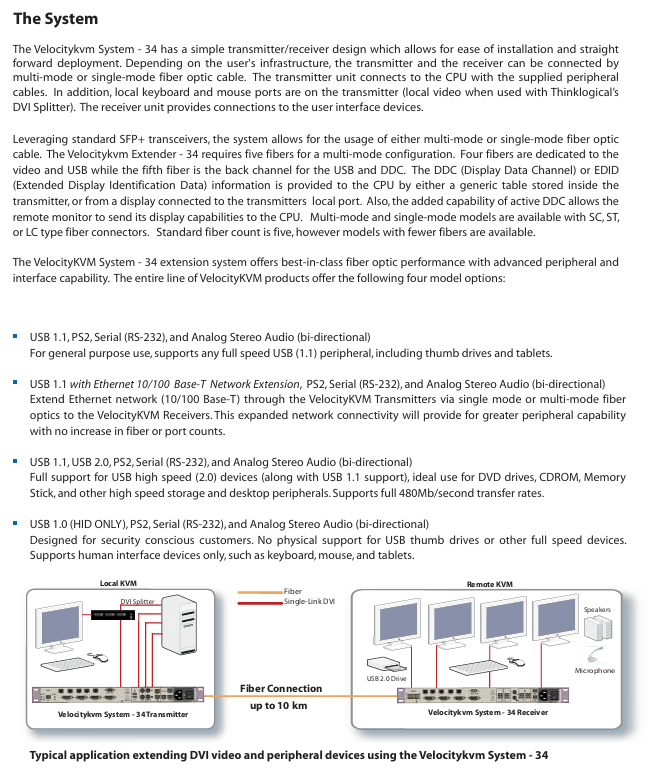
The Velocitykvm-34 series is a four screen single link DVI KVM fiber optic extension system that uses a "transmitter receiver" architecture to achieve remote separation and control of computers and peripherals through single-mode/multi-mode fibers. It supports video, audio USB、 The synchronous transmission of multiple signals through serial ports solves the three major pain points of "long-distance signal attenuation, high-resolution uncompressed transmission, and compatibility with multiple peripherals".
2. Core values
Uncompressed high-definition transmission: relying on patented MRTS (Multi Rate Transmission System) technology, 6.25Gbps bandwidth supports all single link DVI resolutions (such as 1920 × 1080) 1200@60Hz )No frame loss, no compression, zero image delay;
Ultra long distance coverage: Single mode fiber can transmit up to 10km, and multimode fiber (OM3 enhanced type) can transmit up to 1000m, meeting the deployment needs of large parks, cross buildings, and other long-distance environments;
Multi interface compatibility: integrated with USB (HID/1.1/2.0), PS2, RS-232 serial port, bidirectional stereo audio, compatible with keyboards, mice, USB drives, high-speed storage devices, microphones and other peripherals;
High security: Provides "HID only" models (with USB storage devices disabled) to meet the security control needs of classified scenarios such as command centers and financial data centers.

Product classification and core differences
The series includes four core models, all of which support four screen DVI output, PS2, RS-232 serial port, and bidirectional audio. The core difference lies in USB function and network expansion capability. The specific classifications are as follows:
Model Type Core Interface Configuration Transmission Rate Applicable Scenarios
USB 1.0 HID (only) supports USB ergonomic devices (keyboard, mouse, drawing board), disabled USB storage - classified scenarios (such as military command center, financial data center), to prevent data leakage
USB 1.1 supports USB 1.1 full speed peripherals (USB flash drives, tablets, low-speed printers) at 12Mbps for regular office scenarios, without the need for high-speed USB devices
USB 1.1+Ethernet (10/100Base-T) USB 1.1 functionality+Ethernet expansion, capable of transmitting network signals via fiber optic USB 12Mbps; Ethernet 100Mbps requires simultaneous extension of network and KVM signals in scenarios such as remote laboratories and distributed offices
USB 1.1+USB 2.0 compatible with USB 1.1 (low-speed) and USB 2.0 (high-speed) devices. USB 2.0 can reach 480Mbps and requires high-speed peripherals, such as DVD drives, high-speed portable hard drives, and professional scanners
In addition, all models offer single-mode/multi-mode fiber options, and fiber connectors support LC, SC, and ST types to adapt to different fiber infrastructure.
Key technical parameters
1. Transmission performance parameters
Parameter category specification details
Video signal single link DVI-D, supporting all resolutions (such as 1920 × 1080) 1080@60Hz 1920 × 1200@60Hz )
Transmission bandwidth of 6.25Gbps (MRTS technology), no compression, no frame loss
Fiber optic distance - multimode: OM1 (62.5/125 μ m) 50m; OM2(50/125μm)350m; OM3(50/125μm)750m; OM3 Enhanced 1000m
-Single mode: OS2 (9/125 μ m) 10km (for distances exceeding 10km, please contact the manufacturer for customization)
The standard number of optical fibers is 5 cores (4 cores for video/USB, 1 core for USB/DC feedback), supporting customized models with fewer cores
2. Physical and environmental parameters
Parameter category specification details
Size 19 inch rack mount (EIA standard), 1U height (4.40cm), width 44.5cm, depth 36.1cm
The weight of a single machine is 11lbs (4.99kg), and the transportation weight of the transmitter+receiver set is 27lbs (12.25kg)
Power supply wide voltage 100-240V AC (47-63Hz), single machine power consumption 40W
Working environment temperature 0-50 ℃ (32-122 ℉), humidity 5% -95% RH (non condensing)
Certified to comply with electrical safety standards in the United States, Canada, and the European Union (such as CE, FCC, cUL)
12 months warranty (expandable extended warranty)
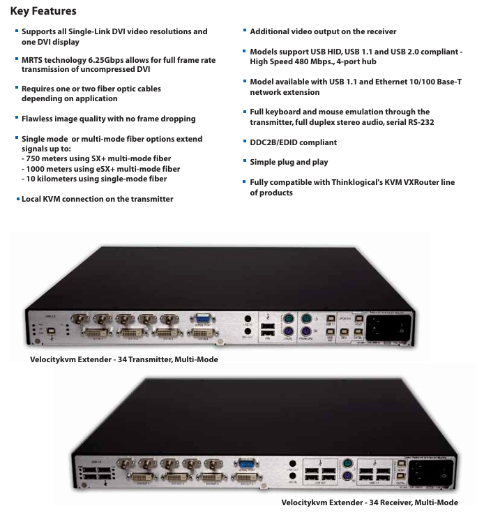
3. Interface configuration (transmitter vs receiver)
Equipment interface type and quantity remarks
Transmitter - Video: DVI-D (4, connected to computer)
-USB: USB B (HID/1.1/2.0, depending on model), local USB A (keyboard/mouse, 2)
-PS2: MiniDIN 6 female head (keyboard/mouse, 1 each; local 1 each)
-Audio: 3.5mm interface (1 microphone, 1 line input)
-Serial port: DB9 female head (RS-232)
-Fiber optic: LC/SC/ST (single-mode SC/APC, multi-mode LC/SC/ST)
-Software upgrade: USB B (3) local interfaces support "near end control", which means that the computer can be directly operated with a keyboard and mouse
Receiver - Video: DVI-D (4, connected to monitor)
-USB: USB A (4, connected to peripherals)
-PS2: MiniDIN 6 female head (keyboard/mouse, 1 each)
-Audio: 3.5mm interface (1 microphone, 1 line output)
-Serial port: DB9 male (RS-232)
-Fiber optic: Same transmitter
-Software upgrade: USB B (2) supports bidirectional audio transmission, enabling sound synchronization between the near end microphone and the far end speaker
System architecture and deployment specifications
1. Core architecture
Adopting a "point-to-point" fiber optic transmission architecture, the signal flow direction is as follows:
Signal acquisition: The transmitter is connected to a computer to collect DVI video, USB/PS2 (keyboard and mouse), audio, and serial port signals;
Fiber optic transmission: The signal is transmitted uncompressed to the receiver through a 5-core fiber optic cable (single-mode/multi-mode optional);
Signal output: The receiver is connected to the display and peripherals (keyboard, mouse, USB flash drive, etc.) to restore the signal and drive the peripherals;
Local control: The transmitter is equipped with a local USB/PS2 interface, supporting direct operation from the computer and achieving dual control of "local+remote".
2. Key deployment requirements
Fiber selection: Strictly match single-mode/multi-mode models, prioritize OM3 (50/125 μ m) for multi-mode to extend transmission distance; Fiber optic cables must comply with TIA/EIA standards to avoid signal loss caused by the use of inferior fiber optic cables;
Interface connection: DVI cables require single link shielded cables (factory supplied 2-meter cables), and USB cables should not exceed 6 feet (approximately 1.8 meters) in length to avoid signal attenuation;
EDID/DDC configuration: The transmitter has a built-in universal EDID table and can also read the EDID of the local display; Support "Active DDC" to allow remote displays to provide resolution information feedback to the computer, ensuring display compatibility;
Power isolation: The transmitter and receiver need to be connected to independent power sources to avoid common ground interference (such as sharing sockets with high-power devices).

Selection method and ordering rules
1. Selection process
Confirm transmission distance and fiber type:
Short distance (≤ 1000m): Choose multi-mode model (suffix "M34");
Long distance (≤ 10km): menu model number (suffix "634");
Select interface function:
Confidential scenario: Select "USB 1.0 HID only" (model includes "H00");
Ordinary office: select "USB 1.1" (model includes "000");
Network expansion required: select "USB 1.1+Ethernet" (model includes "N00");
High speed peripheral: select "USB 1.1+2.0" (model includes "U00");
Determine the fiber optic connector:
Small scale deployment: choose LC interface (model including "LC");
Traditional computer room: select SC/ST interface (model includes "SC"/"ST");
Supporting selection: Select fiber optic modules according to requirements (such as VOP-M12 for multimode and VOP-S36 for single-mode).
2. Example of ordering code
Taking "multi-mode, USB 2.0, LC interface receiver" as an example: VEL-U00M34-LCRX
VEL: Product prefix;
U00: Function code (USB 1.1+2.0);
M34: Fiber type (multimode);
LC: connector type;
RX: Device type (receiver, TX is transmitter).
Typical application scenarios
Broadcasting and post production: The studio computer is separated from the control room monitor (500m away), and four DVI videos are transmitted through multi-mode fiber optic cables. USB 2.0 is connected to high-speed storage devices to achieve real-time editing of 4K materials;
Command Center: The server room (remote end) is separated from the command hall (near end) (3km away), with a menu model number and "HID only" configuration. USB storage is disabled to ensure data security, and an RS-232 serial port control switch is extended;
University laboratory: The teacher's computer (teaching building) is connected to the student's experimental equipment (laboratory, 800m away) through multimode fiber optic cable. The USB 1.1+Ethernet model supports extended network and KVM, and students can remotely operate the experimental equipment;
Large digital signage: The central control computer (computer room) in the shopping mall is connected to multiple digital screens (on different floors, at a distance of 300m) through multimode fiber optic cables, and four DVI screens are used to drive screens in different areas, achieving unified content control.
Precautions and maintenance suggestions
Signal interference prevention: Fiber optic cables should be kept away from strong electrical lines (≥ 1m), and USB/audio cables should be avoided from being laid in parallel with power lines to prevent electromagnetic interference from causing image snowflakes and audio noise;
Regular maintenance: Check the cleanliness of fiber optic connectors every quarter (wipe with specialized fiber optic cleaning paper) to avoid signal attenuation caused by dust; Annual testing of power supply voltage stability to prevent voltage fluctuations from damaging equipment;
Troubleshooting: If there is no signal in the video, priority should be given to checking the fiber optic link (using an optical power meter to measure light attenuation); When there is no response from the USB peripheral, confirm whether the model supports the device (e.g. "HID only" model does not support USB drives);
Software upgrade: Upgrade firmware through the USB B interface of the transmitter/receiver, and do not turn off the power during the upgrade process to avoid device damage.

- YOKOGAWA
- Reliance
- ADVANCED
- SEW
- ProSoft
- WATLOW
- Kongsberg
- FANUC
- VSD
- DCS
- PLC
- man-machine
- Covid-19
- Energy and Gender
- Energy Access
- Renewable Integration
- Energy Subsidies
- Energy and Water
- Net zero emission
- Energy Security
- Critical Minerals
- A-B
- petroleum
- Mine scale
- Sewage treatment
- cement
- architecture
- Industrial information
- New energy
- Automobile market
- electricity
- Construction site
- HIMA
- ABB
- Rockwell
- Schneider Modicon
- Siemens
- xYCOM
- Yaskawa
- Woodward
- BOSCH Rexroth
- MOOG
- General Electric
- American NI
- Rolls-Royce
- CTI
- Honeywell
- EMERSON
- MAN
- GE
- TRICONEX
- Control Wave
- ALSTOM
- AMAT
- STUDER
- KONGSBERG
- MOTOROLA
- DANAHER MOTION
- Bentley
- Galil
- EATON
- MOLEX
- Triconex
- DEIF
- B&W
- ZYGO
- Aerotech
- DANFOSS
- KOLLMORGEN
- Beijer
- Endress+Hauser
- schneider
- Foxboro
- KB
- REXROTH
- YAMAHA
- Johnson
- Westinghouse
- WAGO
- TOSHIBA
- TEKTRONIX
- BENDER
- BMCM
- SMC
- HITACHI
- HIRSCHMANN
- XP POWER
- Baldor
- Meggitt
- SHINKAWA
- Other Brands
- UniOP
- KUKA
- IBA
- Beckhoff
- ADLINK
-
ADLINK HPCI-14S12U - Industrial Control Backplane 12PCI Backplane PCI-14S Passive Backplane
-
ADLINK PCIe-GIE74C - image acquisition card 4-CH GigE Vision PoE+ Frame Grabber
-
ADLINK PCI-8164 - control card 4-Axis Advanced Motion Controller Board
-
ADLINK PCIe-U304 - 4 Port USB3 PCIe Frame Grabbers USB Screw Hole Card
-
ADLINK PCI-9112 - Multi-Function Data Acquisition Card DAQ Card
-
ADLINK PCI-7432 - 51-12013-0A50 4-CH Isolated Numérique I/O PCI Cartes Digital I/O Card
-
ADLINK PCA-6106P3-0C1 REV.C1 - backplane 6-Slot Passive Backplane Board
-
ADLINK PCI-7224 - 24-CH Opto-Isolated Digital I/O PCI Board
-
ADLINK CPCI-7433R(G) - Digital Input Board Rear I/O CompactPCI Card
-
ADLINK EBP-13E4 - 51-46703-0A30 Industrial PC Backplane Passive Backplane
-
ADLINK PCIE-HDV62 - Image acquisition card High Definition Video Frame Grabber
-
ADLINK EBP-13E4 - 51-46703-0A30 Industrial Backplane Board Passive Backplane
-
ADLINK 90111-B1 / CPCI-6770 - PCB CPU MODULE CompactPCI Single Board Computer
-
ADLINK PCI-7248 - DATA ACQUISITION PCI CARD 48-CH Parallel Digital I/O Board
-
ADLINK PCI-7230 - 51-12003-0a50 board PCI7230 32-CH Isolated Digital I/O Card
-
ADLINK PCI2A000CB - 51-20000-0B30 Multi-Function DAQ Card Baseboard
-
ADLINK PCI-8134-005 - 4-Axis Motion Controller Card
-
ADLINK PCI-7224 - 24-CH Opto-Isolated Digital I/O PCI Card
-
ADLINK PCI-7434 - 64-CH Isolated Digital Output Card
-
ADLINK PCI-8132 - motion control card 2-Axis Servo & Stepper Controller
-
ADLINK PCI-8134 - Motion Controller PCI Card 4-Axis Controller Board
-
ADLINK PCI-8164 - Motion Control Card 51-12406-0A40 4-Axis Controller
-
ADLINK 51-12001-0C20 - Circuit Board Data Acquisition Interface Module Hardware
-
ADLINK NuPR0-840 - industrial control motherboard Full-Size PICMG CPU Board
-
ADLINK PCI-7444 - 51-12023-0A10 card 128-CH Isolated Digital Output Board
-
ADLINK PCI-1612B - data acquisition card 4-Port RS-232/422/485 Serial Communication Card
-
ADLINK PCI-6208V 009 - 8/16-CH 16-Bit Analog Output Cards PCB-I-E-482=6BX3
-
ADLINK NUPRO-935A/LV - industrial control motherboard Full-Size PICMG SBC Board
-
ADLINK PCI-9114DG - Multi-Function DAQ Card Data Acquisition PCI Card
-
ADLINK ACL-7130 - Data acquisition card Isolated Digital I/O Board
-
ADLINK ABX-6300D-4E1-BP - board ABX6300D4E1BP Video Interface Expansion Card
-
ADLINK CPCI-6940 - CPCI-6940/D1539/M16-0(EA)-000E 6U CompactPCI Processor Board
-
ADLINK NuPRO-760 - industrial control motherboard Half-Size PICMG SBC CPU Board
-
ADLINK IMB-M42H (G)-0020 - industrial control motherboard LGA1155 Micro-ATX Mainboard
-
ADLINK RTV-24 / PCI-MP4S - 51-12519-1C30 4-Channel Real Time Video Capture Board
-
ADLINK PCI-8134 - 4-Axis Servo & Stepper Motion Controller Card
-
ADLINK MXC-6101D - V.PC000.002.ST.00 Box PC Configurable Embedded Computer
-
ADLINK PCI-8134A - 51-12421-0A10 Motion Control Card 4-Axis Controller Card
-
ADLINK DIN-100S / DIN-100SA1 - Technology SCSI-II TB 100-PIN Terminal Block Board
-
ADLINK DIN-812M001 / DIN812M001 - 51-14034-0A1 51140340A1 Terminal Module Breakout Interface
-
ADLINK PCI-8164 - Servo motion control 4-Axis Advanced Controller Card
-
ADLINK PCIe-GIE64 - Acquisition card GigE Vision PoE+ Frame Grabber
-
ADLINK M-302 - Industrial control motherboard ATX PC Board Mainboard
-
ADLINK PCI-8134 - Motion Controller PCI Card 4-Axis Controller Board
-
ADLINK PCI-RTV24 - Image capture card Analog Video Frame Grabber
-
ADLINK PCI-8102 - Motion control card 2-Axis Servo & Stepper Controller Board
-
ADLINK PCI-9112 REV.B1 - Card Multi-Function Data Acquisition Card
-
ADLINK HSI-DI32-M-N / HSL-TB32-M-DIN - Discrete I/O MODULE Distributed Automation Module System
-
ADLINK PCI-7296 - IO card REV.A3 96-CH Parallel Digital I/O Card
-
ADLINK DIN-814P-A4 / 814Y - terminal board Motion Control Interface Block
-
ADLINK DIN-814P-A4 - 51-14056-0A10 PCB-I-E-2736=ZA01 Screw Terminal Board Breakout
-
ADLINK M-322 - motherboard Industrial Control Computer Mainboard
-
ADLINK NUPRO-406 REV:B1 - industrial control motherboard Full-Size PICMG CPU Board
-
ADLINK AMP-204C - card DSP-Based 4-Axis Advanced Pulse-Train Controller
-
ADLINK HPCI14S REV.B1 - industrial computer baseboard 14-Slot Passive Backplane
-
ADLINK PCI-7250 - 8-CH Relay Output & 8-CH Isolated DI PCI Card
-
ADLINK EBP-13E2 - baseplate Passive Backplane Industrial Computer Chassis Board
-
ADLINK LPCI-3488A - PCI-GPIB card 51-12801-0A30 acquisition card IEEE-488 Interface Board
-
ADLINK PCI-6216V-GL - 51-12201-0C30 16-CH 16-Bit Voltage Analog Output Card
-
ADLINK ACL-8454 - 16-CH Isolated Digital I/O & 4-CH Counter Card
-
ADLINK HPCI-9S7U - backplane Passive Backplane Compatible with NuPRO-A301 852 841 842
-
ADLINK DAQ-2010-007 - Simultaneous-Sampling Multi-Function Data Acquisition Card
-
ADLINK MP-C154 - 51-64205-0A10 Motion Control Card 4-Axis Controller Board
-
ADLINK MXE-202/mSSD16B/WiFi-BT - Matrix Rugged I/O Platform Embedded Fanless Computer
-
ADLINK CM-920-R-17 - PC/104-Plus Single Board Computer Module Intel Celeron M
-
ADLINK PCI-7250 NSMP - 8-CH Relay Output & 8-CH Isolated DI Card
-
ADLINK PCI-8164 - 4-Axis Motion Controller PCI Card W/ Cable and Breakout Box
-
ADLINK EMX-100 - Ethernet-based 4-axis Motion Controllers Distributed Motion Module
-
ADLINK PCI-8134A - Press control card 4-Axis Motion Controller Board
-
ADLINK M-845EG REV:3.2 - industrial motherboard Pentium 4 Socket 478 Micro-ATX
-
ADLINK PCI-9114A Rev A2 DG - card High-Resolution Multi-Function Data Acquisition Board
-
ADLINK IEC-915GV - REV 1.1 Industrial motherboard Socket 478 CPU Board
-
ADLINK PCI-9111DG(G) - Data Acquisition Card Multi-Function DAQ Card
-
ADLINK HPCI-15S10 REV:B2 - Industrial computer base plate Passive Backplane Board
-
ADLINK NuPR0-840 / NuPR0-840DV - industrial control motherboard Full-size PICMG CPU Board
-
ADLINK RTV-24 / PCI-MP4S - 51-12519-1C30 4-Channel Real Time Video Capture Board
-
ADLINK NUPRO-780 - industrial control motherboard Pentium III Single Board Computer
-
ADLINK PCI-7296 - 0050 card 96-CH Opto-Isolated Parallel DIO Card Set
-
ADLINK NUPRO-780 - industrial control motherboard PICMG Full-Size SBC
-
ADLINK PCI-7248 - 51-12006-0A3 002 Pci 7248 48-CH Parallel Digital I/O Card
-
ADLINK cPCI-6626 - 6U CompactPCI 2.0 Blades i7-2710QE PCB-I-E-2570=9N41
-
ADLINK MXC-6322D(G) - Industrial Fanless Computer
-
ADLINK cPCI-8168-004 - CompactPci NulPC Motion Control Board 51-36402-0A3
-
ADLINK CPCI-7300[G] - COMPACTPCI Digital I/O Card Data Acquisition
-
ADLINK CPCI-6626/2710/M4G - COMPACTPCI COMPUTER BOARD
-
ADLINK cPCI-8168-009 - cPCI NulPC Motion Control Board
-
ADLINK cPCI-6626/2710/M4G - VME CPU Board Computer Board
-
ADLINK CPCI-R6200(G)-0040 - COMPACTPCI CONTROL BOARD
-
ADLINK CPCI-3840/PM18/M1G(G)-3650 - COMPACTPCI CPU Module Single Board Computer
-
ADLINK cPCI-7248 - 48-CH Opto-22 Compatible Digital I/O Module
-
ADLINK DLAP-211-JNX - NVIDIA Jetson Xavier NX Edge AI Inference Platform
-
ADLINK cPCI-3544 - Series 4-Port RS-422/485 Isolated Serial Communications Card
-
ADLINK CM1-86DX3 - PC/104 SBC Stanley Vortex86DX3 CPU 2GB Ram
-
ADLINK DLAP-211-JNX - NVIDIA Jetson Xavier NX Edge AI Inference Platform
-
ADLINK cPCI-3544 - Series 4-Port RS-422/485 Isolated Serial Communications Card
-
ADLINK CM1-86DX3 - PC/104 SBC Stanley Vortex86DX3 CPU 2GB Ram
-
ADLINK PCI-7433 - switch value acquisition card Isolated Digital Input Card
-
ADLINK PCI-9112 - 51-12252-0D20 Multi-Function Data Acquisition Card
-
ADLINK NUPRO-A301 REV:1.4 - industrial control motherboard PICMG Full-Size SBC
-
ADLINK 51-18502-0A10 - Frame Grabber Image Acquisition Interface Card
-
ADLINK PCI-7296 - 51-12009-0A50 PCB-I-E-925=6DX1 96-CH Parallel Digital I/O Board
-
ADLINK PCI-8132 GP A2 - Motion Control Card 2-Axis Servo & Stepper Controller
-
ADLINK PCI-7442 - switch quantity card data acquisition card 64-CH Isolated Card
-
ADLINK HPX-13S4 - baseboard PICMG 1.3 Passive Backplane Chassis Baseplate
-
ADLINK NuPRO-590 / NTC-567-ZM-F36 - Single Board Computer PCB-I-E-1853=9L21 Half-Size SBC
-
ADLINK PCIe-8332 - 16-axis plate Motion Control Hardware Card
-
ADLINK NuPRO-775 REV.B1 - motherboard Pentium 4 Full-Size PICMG SBC
-
ADLINK PXI-3920 - Embedded Controller 3U PXI cPCI System Intelligence Board
-
ADLINK PCI-8134 - driver card motion control card 4-Axis Controller Board
-
ADLINK HSL-DI32-M-N-011 / HSL-TB32-M-DIN - Digital Input & Base Module PLC Distributed I/O System
-
ADLINK PCI-6216V-206 / PCI-208V 009 - 16 CH 16bit analog output card
-
ADLINK NuPro-E330 - 51-41805-0A20 PCB Single Board Computer Host Board
-
ADLINK PCI-1622C - Card 8-Port RS-232/422/485 PCI Serial Communication Board
-
ADLINK PCIe-7432 - 51-18402-0A10 Carte PCIe Avec Plage D'Entrée Élevée Isolated DIO Card
-
ADLINK PCI-7250 - PCI Acquisition Card 8-CH Relay Output Isolated DI Card
-
ADLINK PCI-7230 - 32-CH Isolated Digital I/O Card
-
ADLINK PCI-8164 - PCB 4-Axis Motion Controller Card
-
ADLINK PCI-7854 - Collection card High-Speed Link Distributed Motion Controller
-
ADLINK NuPRO-935A/LV - industrial control computer motherboard Full-Size PICMG SBC
-
ADLINK IMB-M40H - motherboard IH61-AA4 1155 LGA1155 Micro-ATX Mainboard
-
ADLINK PCI-7248 - Linhua 51-12006-0A40 48-CH Parallel Digital I/O Card
-
ADLINK HPCI-14S12U - Linhua industrial computer baseboard Passive Backplane
-
ADLINK PCI-8132 Rev.A2 - 2-Axis Servo & Stepper Motion Controller Card
-
ADLINK ACL-8111 - ISA card Multi-Function DAQ Card
-
ADLINK ACL-8111 - ISA card Multi-Function Data Acquisition Board
-
ADLINK PCI-7200 REV.A3 - Digital I/O card 12MB/s High-Speed Parallel Digital I/O
-
ADLINK PCI-7296 REV.A3 - 96-CH High-Density Opto-Isolated DIO Card
-
ADLINK PCI-7434 - 64-CH Isolated Digital Output Card

K-JIANG

Add: Jimei North Road, Jimei District, Xiamen, Fujian, China
Tell:+86-15305925923