
K-WANG


SIEMENS MOBY I Configuration, Installation and Service
SIEMENS MOBY I Configuration, Installation and Service
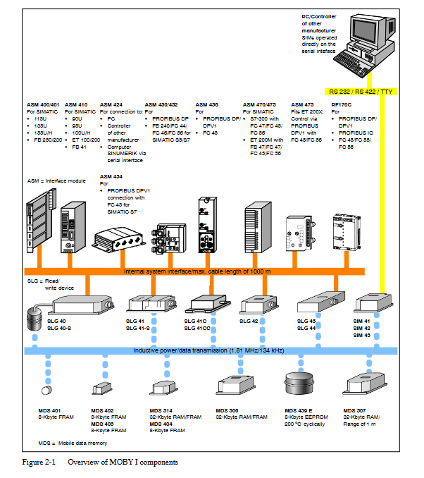
MOBY I is a high-performance radio frequency identification system (order number 6GT2 097-4BA00-0EA2) released by Siemens in 2007. Its core is used for contactless material flow and production process optimization in industrial scenarios. It consists of a mobile data storage (MDS), a read-write device (SLG), an interface module (ASM), and supporting accessories. It supports 8-32 kbytes storage capacity, 0-1000 mm read-write distance, -25 ° C to 200 ° C (cyclic) working temperature, and can be connected to SIMATIC S5/S7, PC and other devices as well as PROFIBUS protocol. The document covers system configuration, installation specifications, component parameters, fault troubleshooting, and other content in detail. Only qualified professionals are allowed to operate it to ensure safety and equipment. Compatibility.
Core Component Details
2.1 Mobile Data Storage (MDS)
Comparison of core parameters
MDS model storage capacity, working temperature protection level, read-write distance (max), special characteristics
MDS 401 8 kbytes (FRAM) -25~+85 ° C IP67 10 mm circular design, suitable for small carriers
MDS 404 8 kbytes (FRAM) -25~+85 ° C IP68 25 mm square design, compatible with metal installation
MDS 507 32 kbytes (RAM) -25~+70 ° C IP65 1000 mm long-distance transmission, battery powered
MDS 514 32 kbytes (FRAM) -25~+85 ° C IP68 90 mm high storage capacity, resistant to harsh environments
MDS 439E 8 kbytes (EEPROM) cyclic 200 ° C IP68 125 mm high temperature resistance, suitable for painting and drying scenarios
Common characteristics
Storage type: Supports RAM (requires battery), FRAM (no battery), EEPROM (high stability)
Data retention: FRAM/EEPROM data is retained for 10 years, RAM relies on battery backup
Chemical resistance: The shell material (polyamide 12, PPS) is resistant to industrial chemicals such as oil, grease, acid and alkali
2.2 Read Write Devices (SLG)
Comparison of core parameters
SLG model read-write distance range, working temperature protection level, transmission window size (L × W), applicable scenarios
SLG 40 2~8 mm -25~+70 ° C IP65 diameter 18 mm short distance precise recognition, small assembly line
SLG 42 0~55 mm -25~+70 ° C IP65 90 × 36 mm medium distance, dynamic transmission of moderate data volume
SLG 43 0~100 mm -25~+70 ° C IP65 140 × 60 mm medium to long distance, large transmission window
SLG 44 100~800 mm -25~+70 ° C IP63 1200 × 300 mm long distance, high-speed moving scene (up to 120 km/h)
SLG 41C 0~15 mm -25~+70 ° C IP67 30 × 8 mm compact, high protection, harsh environment
Common characteristics
Transmission frequency: power transmission 134 kHz, data transmission 1.81 MHz
Interface standard: RS 422, transmission rate 19200 baud
Interference Suppression: Supports sensitivity adjustment for reception and adapts to industrial interference environments
2.3 Interface Module (ASM)
Core types and adaptation scenarios
ASM model docking interface supports SLG quantity protection level adaptation controller core functions
ASM 400/401 SIMATIC S5 bus 4 (parallel) IP00 SIMATIC S5-115U~155U basic control, supporting FB 250/230 function blocks
ASM 450/452 PROFIBUS DP/DPV1 2 (multiplex/pseudo parallel) IP67 various PLC/PC industrial bus docking, supporting file processors
ASM 470/475 SIMATIC S7 bus 2 (multiplex/parallel) IP20 SIMATIC S7-300/ET 200M high-speed data transmission, compatible with S7 system
ASM 424 RS 232/422 4 (parallel) IP40 PC/external controller serial port docking, supporting 3964R protocol
ASM 473 PROFIBUS DPV1 1 IP67 ET 200X distributed I/O scenario, high protection
2.4 Supporting Accessories
Software: MOBY Software (order number 6GT2 080-2AA10), including FB/FC function blocks, drivers, and diagnostic tools
Hardware:
Wide range power supply (6GT2 494-0AA00): 100~230V AC to 24V DC, output 2.2A
STG I handheld terminal (6GT2 003-0CA00): mobile read/write, debugging, supports Chinese and English menus
ES 030-K Collection Station (6AW5 451-3): Multi interface integration, compatible with barcode/MOBY systems
Connecting cable: shielded cable (6-core+shielded), maximum length 1000 m, core wire cross-section 0.07~1.5 mm ²
System configuration and installation specifications
3.1 Core Configuration Principles
Transmission window: SLG generates induced alternating field, MDS needs to be within the effective field strength range (Sg is the limit distance), and dynamic transmission needs to meet the transmission cycle
T V ≥ t K (t K is the communication time)
Metal influence: Metal will reduce the transmission window, and a metal free area (minimum 10-80 mm from the edge of MDS/SLG to the metal) needs to be reserved, which can be isolated by plastic brackets (spacing 8-20 mm)
Distance requirement:
Minimum distance between SLGs: 50 mm (SLG 40)~6000 mm (SLG 44)
Minimum distance between MDS: 50 mm (SLG 40)~4000 mm (MDS 507)
3.2 Special Configuration Instructions
MDS 507+SLG 44 (long-distance combination):
ABTAST parameter (scan interval) needs to be configured to avoid the battery running out too quickly. It is recommended t ABTAST≤1.2 sec
The transmission window is divided into a startup area (MDS ready) and a processing area (data transmission), with an angle deviation of ≤ 45 °
MDS 439E (high-temperature resistant combination):
The cyclic working temperature is ≤ 200 ° C, and the heating cooling cycle needs to be controlled (such as heating at 200 ° C for 1 hour and then cooling for>2 hours)
When the temperature is greater than 85 ° C, the transmission window parameters need to be multiplied by an offset factor C (0.7~1.05)
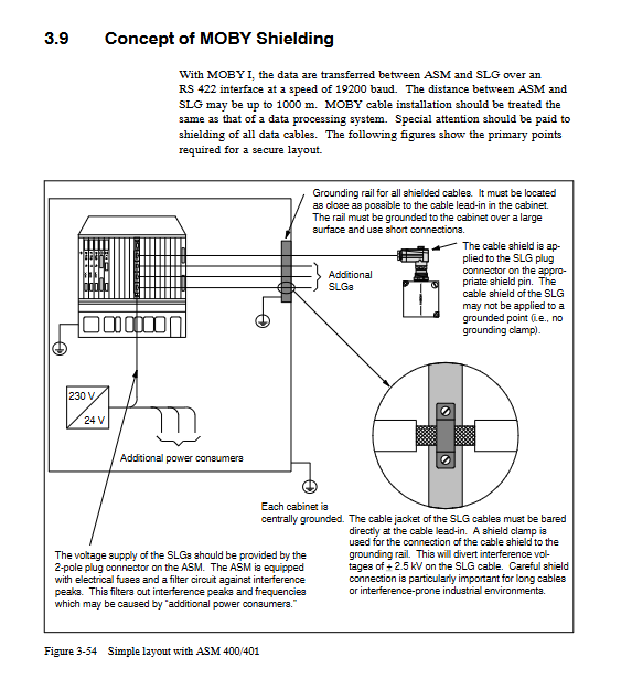
3.3 EMC and Grounding Standards
Shielding requirement: Both ends of the cable should be grounded, and the shielding layer should be connected to the cabinet over a large area to avoid shielding interruption
Equipotential connection: equipotential line cross-section ≥ 10 mm ², reducing interference caused by potential difference
Cabinet layout: Power components and control components are separated (spacing ≥ 10 cm), and signal lines and power lines are laid in separate slots
Interference suppression: Coil type equipment requires the addition of a freewheeling diode/RC circuit, and a filter should be installed at the power inlet
Troubleshooting and compatibility
4.1 Common fault codes (core)
Error code (hex) fault type troubleshooting direction
01 There is an error in removing MDS from the transmission window. Check the position of MDS
04 MDS memory error initializing MDS, checking battery status
06 SLG field interference increases SLG spacing, check shielded cables
0E ECC error enabled ECC driver, reinitialize MDS
80 MDS battery low voltage replacement MDS battery
4.2 Compatibility Description
Alternative models: The document provides alternative models for discontinued MDS/SLG/ASM models (as of September 2004), such as MDS 114 replaced by MDS 404 and SLG 44-ZA07 replaced by SLG 44 (6GT2 001-0DA10-0AX0)
Version compatibility: New components (such as ASM 452) are compatible with old systems and require updating the GSD file configuration
Summary of Key Technical Indicators
Category key indicator numerical range
Storage capacity of 8~32 kbytes
Transmission read-write distance 0~1000 mm
Transmission rate ≥ 0.8 millisecond/byte
Environmental working temperature -25 ° C~200 ° C (cyclic)
Protection level IP20~IP68
Communication protocols PROFIBUS DP/DPV1, RS 232/422, 3964R
Transmission frequency 134 kHz (power), 1.81 MHz (data)
- YOKOGAWA
- Reliance
- ADVANCED
- SEW
- ProSoft
- WATLOW
- Kongsberg
- FANUC
- VSD
- DCS
- PLC
- man-machine
- Covid-19
- Energy and Gender
- Energy Access
- Renewable Integration
- Energy Subsidies
- Energy and Water
- Net zero emission
- Energy Security
- Critical Minerals
- A-B
- petroleum
- Mine scale
- Sewage treatment
- cement
- architecture
- Industrial information
- New energy
- Automobile market
- electricity
- Construction site
- HIMA
- ABB
- Rockwell
- Schneider Modicon
- Siemens
- xYCOM
- Yaskawa
- Woodward
- BOSCH Rexroth
- MOOG
- General Electric
- American NI
- Rolls-Royce
- CTI
- Honeywell
- EMERSON
- MAN
- GE
- TRICONEX
- Control Wave
- ALSTOM
- AMAT
- STUDER
- KONGSBERG
- MOTOROLA
- DANAHER MOTION
- Bentley
- Galil
- EATON
- MOLEX
- Triconex
- DEIF
- B&W
- ZYGO
- Aerotech
- DANFOSS
- KOLLMORGEN
- Beijer
- Endress+Hauser
- schneider
- Foxboro
- KB
- REXROTH
- YAMAHA
- Johnson
- Westinghouse
- WAGO
- TOSHIBA
- TEKTRONIX
- BENDER
- BMCM
- SMC
- HITACHI
- HIRSCHMANN
- XP POWER
- Baldor
- Meggitt
- SHINKAWA
- Other Brands
- UniOP
- KUKA
- IBA
- Beckhoff
-
LTI SC52.0040.0012.0000.0 - Servo Drive
-
Lti SC52.0040.0012.0000.0 - Servo Drive
-
Milton Industries LTI Tool By Milton LT1240 - 1/2" Drive Lugnut Remover
-
LTi Drives SO84.200.P030.0000.0-W - Servo Spindle Drive
-
LTI DRIVES LSP08-035-320-30-B0R1PY170 - Servo Motor
-
LTI DRIVES SE84.200.SC00.0001.0-W - Servo Drive
-
Lust CDE34.005.W2.2 - Lti Drives Controller
-
LTi SO84.012.0030.0011.2 - ServoOne Servo Drive
-
LTi Drives SO CM-P.0010.11.00.0 - Servo Drive Controller
-
LTi CDE34.017.W3.0 - Servo Drive
-
LTI Drives CDB32.004, C2.0,SH - Positioning Controller
-
LUST CM-CAN1 - LTi DRIVES Communication Module
-
LTi SO84.012.1030.0000.2 - Servo Drive
-
LTI MOOG CDE54.044 - PITCHMASTER FREQUENCY CONVERTER 181-01019
-
MOOG LTI 181-01019 CDE54.044 - PITCHMASTER FREQUENCY CONVERTER
-
Lust LTi Drives CDE34.010,D2.0 - Servo Drive Controller
-
LTI SO84.032.0003.0101.2 - Servo Drive
-
Seagate 9CC132-302 Harris LTI-CS IRT-34-0021-01 - Hard Drive 160GB
-
LTI SO84.032.0003.0001.2 - Servo Drive
-
LTI SO24.007.0070.0000.1 - SERVO CONTROLLER
-
LTi drive CDA32.003.C3.0.H05-01.PC1 - Servo Drive
-
LTI SO84.016.0030.0000.2 - SERVO CONTROLLER
-
LUST LTI CD A34.008,W1.4, BR - SERVO DRIVE
-
MOOG LTI 181-01019 CDE54.044 - PITCHMASTER FREQUENCY CONVERTER
-
LTI MOOG 181-01019 - PITCH Master Servo Drive CDE54.044
-
LTI SERVO ONE SO84.045.0030.0001.2-W - Drive
-
LUST LTi SO84.032.0040.0000.2 - SERVO ONE DRIVE
-
LTi Drives LSH-074-2-30-3 20/T1,G6.1M - SERVO MOTOR
-
LTI SO84.016.0000.0101.2 - servo drive
-
LTI SA54.0550.0033.0000.0 - Servo Drive
-
LTI SA54.0550.0033.0000.0 - Servo Drive
-
LTI LT 4850 - 3/8" Drive 3-Pc Twist Socket Transmission Drain Plug Removal System
-
LTI Tools LT4400-30 Lock Technology - 3/4" Twist Socket 1/2" Drive Lugnut Remover
-
LTI Tools LT-1400C - 1/2 Drive Wheel Torque Extension Tool
-
LTI Tools LT1250 - 1/2" Drive Dual Sided Socket Lug Nut Remover Tool
-
LTI SO84.032.0003.0101.2 - Servo Drive
-
LTI MOOG 181-01019 - PITCH Master Servo Drive CDE54.044
-
MOOG LTI 181-01019 CDE54.044 - PITCHMASTER FREQUENCY CONVERTER
-
MOOG LTI 181-01019 CDE54.044 - PITCHMASTER FREQUENCY CONVERTER
-
MOOG LTI 181-01019 CDE54.044 - PITCHMASTER FREQUENCY CONVERTER
-
LTI SA54.0550.0033.0000.0 - Servo Drive
-
LTI Tools LT-4800 - 7 Piece Twist Socket 3/8" Drive Oil Drain Plug Removal Set
-
LTI SA54.0550.0033.0000.0 - Servo Drive
-
LTI Drive SO24.007.00300000.0 - Servo Drive
-
LTI TOOLS LTI 1400-I - Drive Wheel Torque Extension
-
LTI Tools LT4400-3 - 3/4" 19mm Twist Socket 1/2" Drive Lugnut
-
LTI TOOLS LTI 1400-BB - Drive Wheel Torque Extension
-
LTI SO84.032.0003.0101.2 - Servo Drive
-
LTI Tools LT-4512 - 3/8" Drive 12mm Twist Socket
-
LTI MOTION Luster SO84.032.0003.0001.2 - Servo Drive
-
LTI Tool By Milton LT1600P - 1" Drive Torx Stick
-
LTI Lust VF1424L,HF,OP2,S56 - Variable Frequency Drive
-
LUST CDA32.004,C1.4,H08,B0 - SERVO DFRIVE CM-CAN1 Module
-
LTI SO84.045.0002.0001.2-W - Drive
-
LTI Lust VF1404M,C9,PT1,BR1 - Inverter Type VF1404M
-
LTI SA54.0550.0033.0000.0 - Servo Drive
-
LTI Tools LT-1400C - 1/2" Drive Wheel Torque Extension
-
Lust LTI DRiVES CDA32.006, C3.0, H09 - Variateur De Fr茅quence Frequency Inverter
-
LTI MOOG CDE54.044 - PITCH master SERVO DRIVE
-
LTI MOOG CDE54.044 - PITCH master SERVO DRIVE
-
LTI SO84.143.0020.0101.2-W - servo drive
-
LTI MOTION SC34.0200.0011.0000.0 - Servo drives
-
LTI SO84.032.0003.0001.2 - Servo Drive
-
LTI DRIVES GmbH MS100 - Assembly Set Mounting Kit
-
LTI SO84.032.0003.0001.2 - Servo Drive
-
LTI SO84.032.0003.0001.2 - Servo Drive
-
LTI MOTION SO84.032.0003.0101.2 - servo drive
-
LTI SO84.032.0003.0101.2 - Servo Drive
-
LTI MOOG CDE54.044 - PITCH master SERVO DRIVE
-
LTI MOTION CDE32.004.C2.4 - Servo drives
-
LTI CDD34.032锛學x.x锛孊R锛孭C1 - Servo Drive
-
Lust LTI DRiVES CDA32.006, C3.0, H09 - Inversor De Frecuencia Frequency Inverter
-
Lust SO84.008.0030.1000.0 - Servo One LTi Drive
-
LTI MOTION SO84.032.0003.0101.2 - Servo drives
-
LUST LTi CDA32.004,C1.4 - SERVO DRIVE
-
LTI MOOG CDE54.044 - PITCH Master SERVO DRIVE
-
LTI KEBA CDB32.004 C2.7, SH - PN: 08673530 Frequency Inverter
-
LTI Tools LT-1400C - 1/2" Drive Wheel Torque Extension
-
LTI LT1400-E - 1/2" Drive Wheel Torque Extension
-
LTI MOOG 181-01019 - PITCH master SERVO DRIVE CDE54.044
-
LTI LSN-097-0510-30-560/T1 - Actuator Motor
-
LTI Tools LT 4800 - 7 Piece 3/8" Drive Twist Socket Oil Drain Plug Removal System
-
LTI DRIVES GmbH MS100 - MONTAGESET Assembly Set Mounting Kit
-
Lti SC52.0040.0012.0000.0 - Servo Drive
-
LTI DRIVES GmbH MS100 - Juego De Montaje Assembly Set Mounting Kit
-
LTi DSM4-14.2-21R83-200 - Drives servomoteur Servo Motor
-
MOOG CDE 54.044.GDA - Pitch Master Industrielle Turbine Lti Drive
-
LTI SO24.004.0030.1000.0 - Servo Drive Controller
-
Lti MOOG CDE54.044 - Pitch Master Servo Drive
-
Lust LTI DRiVES CDA32.006, C3.0, H09 - Inverter
-
LTI MOTION GMBH CDB34.006,W3.0,PC1,H39 - Frequency inverter
-
LTI SO84.032.0003.0001.2 - Servo Drive
-
MOOG CDE 54.044.D - Pitch Master Industrielle Turbine Lti Drive
-
LTI TOOLS LT-1460 - 1/2" DRIVE WHEEL TORQUE EXTENSION KIT 5 PIECE SET
-
Lust Cdb32.003, C2.4 - Lti Drives Servoregulador Frecuencia Servo Controller Inverter
-
Lust LTI DRIVES CDA32.006, C3.0, H09 - Frequency Inverter
-
Lust Lti SO82.004.0030.0000.2 - Servo Drive
-
LTI MOTION SC34.0200.0011.0000.0-SL - Servo drives
-
LTI MOTION SA54.0075.0033.0000.0 - Servo drives
-
LTI MOTION SC32.0075.1011.0000.0 - Servo drives
-
LTI Servo-One Junior SO22.006.0080.1000.0 - Servo Controller Servoregler
-
LUST CDA32.004, C1.4, H08, B0 - Servo Drive & LTI CM-CAN1 Module
-
LTI DRIVES LSP08-035-320-30-B0R1PY170 - Servo Motor
-
LUST LTI CDA32.004,C1.4.H08.B0 - SERVO CONTROLLER DRIVES
-
LUST LTi DRiVES CDS44.072LC1.2 - Servo Drive
-
Lti Servo-One Junior SO22.006.0082.1000.0 - Servo Controller Servoregler
-
LUST CDA32.008,C2.0,HF - Lti DRIVES Spindle Drive Inverter
-
LTI SO22.003.0082.0000.0 - Servo Drives One junior Servo Controller Servoregler
-
Lust Lti Drives CM-CAN1 - Communication Module
-
LUST Lti Drives Vf1202s, G8, I6 - Frequency Inverter Drive
-
LTI DRIVES BR-090.03.540.UR.H38 - Bremswiderstand Brake Resistor
-
LTi DRIVES PM-E40.2DRA054P - Wind Turbine Pitch Control Inverter
-
LTi Drives GmbH br-110.01.540-UR - Brake Resistor
-
LTI Drives LSN-097-0960-30-0560/T1,S4,B - Servo Motor
-
LUST CDA34.006.C2.0 - LTI Drives Servoregler
-
LUST LTI DRIVES SERVO ONE JUNIOR SO24.002.0020.0000.1 - Servo Drive Controller
-
LTI MOTION SO84.032.0003.0001.2 - Servo drives
-
LTI DDTD750V2-120 - IBOP ACTUATOR CYLINDER FOR TOP DRIVE
-
LTI CDE32.004, C2.4 - SERVO DRIVE
-
LUST LTI DRIVES CDD34.017 W3.4PC1 - Servo Drive Controller
-
LTI CDA3208,C3,0,HF - AC SERVO DRIVE
-
LUST LTI DRIVES LSH-074-3-30-560/T1,G6.1S - SERVO MOTOR
-
LUST Lti CDB32.004.C2.4.SH - AC Servo Drive
-
LTi CDA32.006, C3.0, H09 - Servo Drive
-
LTI SO22.003.0010.0000.0 - Servo Drive Servo one junior Servoregler Controller
-
LTi Drives DSM4-14.2-21R83-200 - Servo Motor
-
LUST Lti Drives Lsh-097-1-30-560/T1, 1R - Servomotor
-
LTI 1237 - 7 Piece 1/2" Drive Flip Socket Set

K-JIANG

Add: Jimei North Road, Jimei District, Xiamen, Fujian, China
Tell:+86-15305925923