
K-WANG


SIEMENS SENTRON Circuit Protection Equipment with Communication and Measurement Functions
SIEMENS SENTRON Circuit Protection Equipment with Communication and Measurement Functions
SENTRON's circuit protection equipment with communication and measurement functions is the core product of Siemens' intelligent infrastructure series. With SENTRON Powercenter 1000 as the data transmission and reception core, it is compatible with 7 types of terminal devices (including small circuit breakers, arc fault detection devices, fuses, etc.), supports wireless+Bluetooth+Ethernet multi interface communication, and achieves data transmission through Modbus TCP protocol. It can collect electrical parameters and equipment status such as current, voltage, temperature, etc. It has functions such as alarm threshold setting, trip reason recording, remote control, etc. The protection level reaches IP20-IP68, and the working temperature covers -40 ° C to+60 ° C (some models can withstand 200 ° C cyclic high temperature). It is suitable for scenarios such as main distribution panels and sub distribution panels, and can improve the system. Availability and operational transparency, only qualified professionals are allowed to install and debug.
Core Component Details
2.1 Data transmission and reception core: SENTRON Powercenter 1000
Specific specifications of parameters
Order number 7KN1110-0MC00
Interface type Ethernet (Cat5 F/UTP and above), Bluetooth 5.1, wireless
The connection capability can pair up to 24 terminal devices and support parallel operation of 4 devices
Power supply requirement: 24V DC SELV (19.2~28.8V), maximum power consumption of 100mA
Data storage, measurement trend storage for 1 hour to 30 days, with a maximum of 50 message records
Protection level IP20
Environmental temperature operation: -25~+60 ° C; Storage: -40~+85 ° C
Physical dimensions: width 18mm, height 90mm, depth 70mm, net weight 52g
2.2 Terminal devices (7 core models)
Equipment type, core functions, key parameters, protection level
5SL6 COM miniature circuit breaker overload/short circuit protection, power measurement, RCM version supports residual current monitoring rated current 2-32A, trip characteristics B/C, measurement accuracy ± 0.5% IP20 (rear side)/IP40 (front side)
5SV6 COM arc fault detection equipment overload/short circuit/arc fault protection, electrical parameter acquisition rated current 6-32A, breaking capacity 6kA, working temperature -25~+45 ° C IP20 (connection end)/IP40 (front side)
3NA COM fuse short circuit protection, current/temperature monitoring, advance warning rated current 80~315A, size NH2, operation category gG/gFF IP20
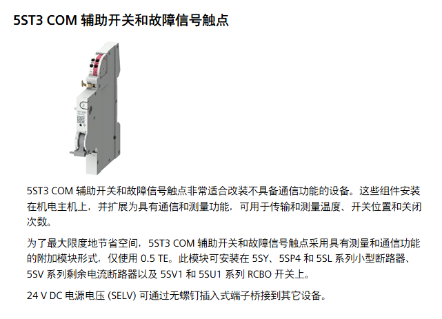
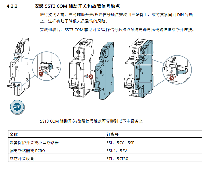
5ST3 COM auxiliary switch/fault signal contact status monitoring (switch position/trip), temperature measurement modular width 0.5TE, power supply 24V DC, current consumption 20mA IP20
3RV2 COM wireless auxiliary switch motor starter protector status monitoring, overload/short circuit trip record width 18mm, working temperature -20~+60 ° C IP20
5ST3 COM RCA remote control auxiliary remote switch, automatic reclosing (ARD), RCD/IR test power supply 100~240V AC, supports 3+3 reclosing attempts IP20
2.3 Supporting software
Mobile: SENTRON Powerconfig mobile (iOS/Android)
Function: Device scanning, pairing debugging, parameter setting, data visualization
Connection methods: Bluetooth (5m~10m), WLAN (same network)
PC end: SENTRON Powerconfig
Function: Project import and export, firmware update, batch parameter configuration
Compatibility: Supports Modbus TCP protocol docking with third-party systems
Installation and commissioning specifications
3.1 Installation Preparation
Delivery inspection: Confirm that the packaging is undamaged, the equipment model is consistent with the order, and the original packaging is retained
Identification requirements: including manufacturer identification (order number/serial number/RF code) and user identification (equipment/location ID+installation date)
Environmental conditions:
Pollution level: Level 2 (conventional)/Level 3 (only 3NA COM)
Temperature: -25~+60 ° C for operation (-10~+55 ° C for 3NA COM), -40~+75 ° C for storage
Humidity: ≤ 93% at 40 ° C (no condensation)
Installation spacing:
The maximum distance between the terminal and Powercenter is ≤ 3m (standard transmission power 0dBm)
When multiple Powercenters are running in parallel, channels need to be distinguished (automatic/manual selection) to avoid interference
3.2 Equipment Installation and Wiring
Installation method: DIN rail card mounting (compliant with EN 60715 standard)
Wiring requirements:
Power supply line: 24V DC SELV adopts screw free plug-in terminals, with a conductor cross-section of 0.2~1.5mm ²
Signal line: 5SL6/5SV6 COM needs to be connected with phase+neutral wire (230V AC)
Shielding requirement: Both ends of the cable should be grounded to avoid parallel laying with the power line
Special requirements:
3NA COM needs to be installed vertically, and electronic modules must not be located above fuses
The installation location of Powercenter should be away from metal surfaces to ensure antenna efficiency
3.3 Debugging Process
Device addition: Add Powercenter 1000 through Bluetooth/WLAN search or manually enter IP address
Terminal pairing: Scan the device RF code (including MAC/installation code) and assign device addresses (1-24)
Parameter configuration:
Communication parameters: IP address (static/DHCP), Bluetooth PIN code, radio transmission power
Measurement parameters: alarm threshold, energy flow direction, RCM measurement range
Control parameters: ARD delay time, RCD test cycle
Function verification: Check LED status (green light is always on as normal), measurement value transmission, alarm response
Core functions and technical features
4.1 Data collection function
Collection parameters:
Electrical parameters: current (0.02~2In), voltage (50~400V), power, electrical energy, power frequency (45~65Hz)
Equipment status: temperature (-25~120 ° C), operating hours, switch cycles, number of trips, residual current (RCM version)
Collection accuracy:
Current/Voltage: ± 0.5%
Power/Electric Energy: ± 1%
Temperature: ± 2~2.5 ° C
Transmission frequency: Key parameters (current/temperature) are transmitted every 2 seconds, and electrical energy/voltage is transmitted every 60 seconds
4.2 Monitoring and alarm functions
Alarm type:
Threshold alarm: overcurrent/undercurrent, overvoltage/undervoltage, overtemperature
Status alarm: tripping operation (overload/short circuit/arc fault), service life warning (operating hours/operating cycle)
Diagnostic alarm: communication error, self-test failure, RCM warning
Alarm settings:
Can turn on/off alarms, adjust threshold and lag values (0-10%)
RCM alarm supports automatic reset or manual confirmation
LED indication: green light (normal), yellow/red light (warning/fault), flashing frequency to distinguish status
4.3 Communication and Control Functions
Communication protocol: Modbus TCP, supports 3 concurrent connections, port 502
Control function:
Remote control: Device switching is achieved through software or wired interfaces
Automatic Recloser (ARD): 3+3 attempts, delay time 10-1800 seconds can be set
Testing functions: RCD testing (compliant with IEC 63024), insulation resistance (IR) testing
Data synchronization: Supports SNTP time synchronization to ensure the accuracy of event timestamps
4.4 Data Storage and Visualization
Trend storage:
Short term: average temperature/current (1 hour, interval of 10 seconds)
Long term: Extreme values of electrical energy/temperature (30 days, with an interval of 1 day)
Visualization method:
Mobile: real-time data, trend charts, alarm message lists
PC end: Project data export (. splx format), batch device management
Upper system docking: supports SENTRON Powermanager, Powercenter 3000, and cloud platform (Insights Hub)
Maintenance and troubleshooting
5.1 Daily Maintenance
Firmware update: executed through PC side Powerconfig, updating Powercenter takes 2 minutes, and terminal devices take 5-15 minutes
Disposal: Comply with local environmental regulations and do not dispose of as household waste
Regular inspection: confirm LED status, wiring tightness, and clear alarm messages
5.2 Common troubleshooting
Solution to Fault Phenomena
Bluetooth cannot find Powercenter 1. Activate device Bluetooth mode (short press button<3 seconds); 2. Check the Bluetooth/GPS on the mobile device; 3. Confirm that the PIN code is entered correctly
Pairing timeout 1. Check device power supply; 2. The backend is still pairing, please be patient and wait; 3. Press and hold the device button for ≥ 10 seconds to reset and retry
Modbus connection failure: 1. Confirm that the device address and register address are correct; 2. Check the Ethernet wiring; 3. Verify function code (read 0x03/0x04, write 0x06/0x10)
The device flashes red light. Press the button briefly to confirm the trip operation; 2. Check the cause of circuit overload/short circuit; 3. Reset the device and then close it again
Firmware update failed 1. Ensure continuous power supply to the device; 2. Check that there is no interference in communication; 3. Confirm that the firmware version matches the device type
Summary of Key Technical Parameters
Category Core Indicators
Protection level IP20 (Powercenter/auxiliary switch)~IP68 (some terminal devices)
Rated voltage 230V AC (single-phase), 400V AC (3NA COM)
Rated current 2~32A (miniature circuit breaker/AFDD), 80~315A (fuse)
Breaking capacity 6kA (5SL6/5SV6 COM), 100kA (3NA COM)
Communication interface Ethernet (Modbus TCP), Bluetooth 5.1, wireless (2400~2483.5MHz)
Storage capacity for up to 30 days of trend data and 50 event messages
Response time switch command response ≥ 1 second, interval between two commands ≥ 10 seconds
- YOKOGAWA
- Reliance
- ADVANCED
- SEW
- ProSoft
- WATLOW
- Kongsberg
- FANUC
- VSD
- DCS
- PLC
- man-machine
- Covid-19
- Energy and Gender
- Energy Access
- Renewable Integration
- Energy Subsidies
- Energy and Water
- Net zero emission
- Energy Security
- Critical Minerals
- A-B
- petroleum
- Mine scale
- Sewage treatment
- cement
- architecture
- Industrial information
- New energy
- Automobile market
- electricity
- Construction site
- HIMA
- ABB
- Rockwell
- Schneider Modicon
- Siemens
- xYCOM
- Yaskawa
- Woodward
- BOSCH Rexroth
- MOOG
- General Electric
- American NI
- Rolls-Royce
- CTI
- Honeywell
- EMERSON
- MAN
- GE
- TRICONEX
- Control Wave
- ALSTOM
- AMAT
- STUDER
- KONGSBERG
- MOTOROLA
- DANAHER MOTION
- Bentley
- Galil
- EATON
- MOLEX
- Triconex
- DEIF
- B&W
- ZYGO
- Aerotech
- DANFOSS
- KOLLMORGEN
- Beijer
- Endress+Hauser
- schneider
- Foxboro
- KB
- REXROTH
- YAMAHA
- Johnson
- Westinghouse
- WAGO
- TOSHIBA
- TEKTRONIX
- BENDER
- BMCM
- SMC
- HITACHI
- HIRSCHMANN
- XP POWER
- Baldor
- Meggitt
- SHINKAWA
- Other Brands
- UniOP
- KUKA
- IBA
- Beckhoff
-
LTI SC52.0040.0012.0000.0 - Servo Drive
-
Lti SC52.0040.0012.0000.0 - Servo Drive
-
Milton Industries LTI Tool By Milton LT1240 - 1/2" Drive Lugnut Remover
-
LTi Drives SO84.200.P030.0000.0-W - Servo Spindle Drive
-
LTI DRIVES LSP08-035-320-30-B0R1PY170 - Servo Motor
-
LTI DRIVES SE84.200.SC00.0001.0-W - Servo Drive
-
Lust CDE34.005.W2.2 - Lti Drives Controller
-
LTi SO84.012.0030.0011.2 - ServoOne Servo Drive
-
LTi Drives SO CM-P.0010.11.00.0 - Servo Drive Controller
-
LTi CDE34.017.W3.0 - Servo Drive
-
LTI Drives CDB32.004, C2.0,SH - Positioning Controller
-
LUST CM-CAN1 - LTi DRIVES Communication Module
-
LTi SO84.012.1030.0000.2 - Servo Drive
-
LTI MOOG CDE54.044 - PITCHMASTER FREQUENCY CONVERTER 181-01019
-
MOOG LTI 181-01019 CDE54.044 - PITCHMASTER FREQUENCY CONVERTER
-
Lust LTi Drives CDE34.010,D2.0 - Servo Drive Controller
-
LTI SO84.032.0003.0101.2 - Servo Drive
-
Seagate 9CC132-302 Harris LTI-CS IRT-34-0021-01 - Hard Drive 160GB
-
LTI SO84.032.0003.0001.2 - Servo Drive
-
LTI SO24.007.0070.0000.1 - SERVO CONTROLLER
-
LTi drive CDA32.003.C3.0.H05-01.PC1 - Servo Drive
-
LTI SO84.016.0030.0000.2 - SERVO CONTROLLER
-
LUST LTI CD A34.008,W1.4, BR - SERVO DRIVE
-
MOOG LTI 181-01019 CDE54.044 - PITCHMASTER FREQUENCY CONVERTER
-
LTI MOOG 181-01019 - PITCH Master Servo Drive CDE54.044
-
LTI SERVO ONE SO84.045.0030.0001.2-W - Drive
-
LUST LTi SO84.032.0040.0000.2 - SERVO ONE DRIVE
-
LTi Drives LSH-074-2-30-3 20/T1,G6.1M - SERVO MOTOR
-
LTI SO84.016.0000.0101.2 - servo drive
-
LTI SA54.0550.0033.0000.0 - Servo Drive
-
LTI SA54.0550.0033.0000.0 - Servo Drive
-
LTI LT 4850 - 3/8" Drive 3-Pc Twist Socket Transmission Drain Plug Removal System
-
LTI Tools LT4400-30 Lock Technology - 3/4" Twist Socket 1/2" Drive Lugnut Remover
-
LTI Tools LT-1400C - 1/2 Drive Wheel Torque Extension Tool
-
LTI Tools LT1250 - 1/2" Drive Dual Sided Socket Lug Nut Remover Tool
-
LTI SO84.032.0003.0101.2 - Servo Drive
-
LTI MOOG 181-01019 - PITCH Master Servo Drive CDE54.044
-
MOOG LTI 181-01019 CDE54.044 - PITCHMASTER FREQUENCY CONVERTER
-
MOOG LTI 181-01019 CDE54.044 - PITCHMASTER FREQUENCY CONVERTER
-
MOOG LTI 181-01019 CDE54.044 - PITCHMASTER FREQUENCY CONVERTER
-
LTI SA54.0550.0033.0000.0 - Servo Drive
-
LTI Tools LT-4800 - 7 Piece Twist Socket 3/8" Drive Oil Drain Plug Removal Set
-
LTI SA54.0550.0033.0000.0 - Servo Drive
-
LTI Drive SO24.007.00300000.0 - Servo Drive
-
LTI TOOLS LTI 1400-I - Drive Wheel Torque Extension
-
LTI Tools LT4400-3 - 3/4" 19mm Twist Socket 1/2" Drive Lugnut
-
LTI TOOLS LTI 1400-BB - Drive Wheel Torque Extension
-
LTI SO84.032.0003.0101.2 - Servo Drive
-
LTI Tools LT-4512 - 3/8" Drive 12mm Twist Socket
-
LTI MOTION Luster SO84.032.0003.0001.2 - Servo Drive
-
LTI Tool By Milton LT1600P - 1" Drive Torx Stick
-
LTI Lust VF1424L,HF,OP2,S56 - Variable Frequency Drive
-
LUST CDA32.004,C1.4,H08,B0 - SERVO DFRIVE CM-CAN1 Module
-
LTI SO84.045.0002.0001.2-W - Drive
-
LTI Lust VF1404M,C9,PT1,BR1 - Inverter Type VF1404M
-
LTI SA54.0550.0033.0000.0 - Servo Drive
-
LTI Tools LT-1400C - 1/2" Drive Wheel Torque Extension
-
Lust LTI DRiVES CDA32.006, C3.0, H09 - Variateur De Fr茅quence Frequency Inverter
-
LTI MOOG CDE54.044 - PITCH master SERVO DRIVE
-
LTI MOOG CDE54.044 - PITCH master SERVO DRIVE
-
LTI SO84.143.0020.0101.2-W - servo drive
-
LTI MOTION SC34.0200.0011.0000.0 - Servo drives
-
LTI SO84.032.0003.0001.2 - Servo Drive
-
LTI DRIVES GmbH MS100 - Assembly Set Mounting Kit
-
LTI SO84.032.0003.0001.2 - Servo Drive
-
LTI SO84.032.0003.0001.2 - Servo Drive
-
LTI MOTION SO84.032.0003.0101.2 - servo drive
-
LTI SO84.032.0003.0101.2 - Servo Drive
-
LTI MOOG CDE54.044 - PITCH master SERVO DRIVE
-
LTI MOTION CDE32.004.C2.4 - Servo drives
-
LTI CDD34.032锛學x.x锛孊R锛孭C1 - Servo Drive
-
Lust LTI DRiVES CDA32.006, C3.0, H09 - Inversor De Frecuencia Frequency Inverter
-
Lust SO84.008.0030.1000.0 - Servo One LTi Drive
-
LTI MOTION SO84.032.0003.0101.2 - Servo drives
-
LUST LTi CDA32.004,C1.4 - SERVO DRIVE
-
LTI MOOG CDE54.044 - PITCH Master SERVO DRIVE
-
LTI KEBA CDB32.004 C2.7, SH - PN: 08673530 Frequency Inverter
-
LTI Tools LT-1400C - 1/2" Drive Wheel Torque Extension
-
LTI LT1400-E - 1/2" Drive Wheel Torque Extension
-
LTI MOOG 181-01019 - PITCH master SERVO DRIVE CDE54.044
-
LTI LSN-097-0510-30-560/T1 - Actuator Motor
-
LTI Tools LT 4800 - 7 Piece 3/8" Drive Twist Socket Oil Drain Plug Removal System
-
LTI DRIVES GmbH MS100 - MONTAGESET Assembly Set Mounting Kit
-
Lti SC52.0040.0012.0000.0 - Servo Drive
-
LTI DRIVES GmbH MS100 - Juego De Montaje Assembly Set Mounting Kit
-
LTi DSM4-14.2-21R83-200 - Drives servomoteur Servo Motor
-
MOOG CDE 54.044.GDA - Pitch Master Industrielle Turbine Lti Drive
-
LTI SO24.004.0030.1000.0 - Servo Drive Controller
-
Lti MOOG CDE54.044 - Pitch Master Servo Drive
-
Lust LTI DRiVES CDA32.006, C3.0, H09 - Inverter
-
LTI MOTION GMBH CDB34.006,W3.0,PC1,H39 - Frequency inverter
-
LTI SO84.032.0003.0001.2 - Servo Drive
-
MOOG CDE 54.044.D - Pitch Master Industrielle Turbine Lti Drive
-
LTI TOOLS LT-1460 - 1/2" DRIVE WHEEL TORQUE EXTENSION KIT 5 PIECE SET
-
Lust Cdb32.003, C2.4 - Lti Drives Servoregulador Frecuencia Servo Controller Inverter
-
Lust LTI DRIVES CDA32.006, C3.0, H09 - Frequency Inverter
-
Lust Lti SO82.004.0030.0000.2 - Servo Drive
-
LTI MOTION SC34.0200.0011.0000.0-SL - Servo drives
-
LTI MOTION SA54.0075.0033.0000.0 - Servo drives
-
LTI MOTION SC32.0075.1011.0000.0 - Servo drives
-
LTI Servo-One Junior SO22.006.0080.1000.0 - Servo Controller Servoregler
-
LUST CDA32.004, C1.4, H08, B0 - Servo Drive & LTI CM-CAN1 Module
-
LTI DRIVES LSP08-035-320-30-B0R1PY170 - Servo Motor
-
LUST LTI CDA32.004,C1.4.H08.B0 - SERVO CONTROLLER DRIVES
-
LUST LTi DRiVES CDS44.072LC1.2 - Servo Drive
-
Lti Servo-One Junior SO22.006.0082.1000.0 - Servo Controller Servoregler
-
LUST CDA32.008,C2.0,HF - Lti DRIVES Spindle Drive Inverter
-
LTI SO22.003.0082.0000.0 - Servo Drives One junior Servo Controller Servoregler
-
Lust Lti Drives CM-CAN1 - Communication Module
-
LUST Lti Drives Vf1202s, G8, I6 - Frequency Inverter Drive
-
LTI DRIVES BR-090.03.540.UR.H38 - Bremswiderstand Brake Resistor
-
LTi DRIVES PM-E40.2DRA054P - Wind Turbine Pitch Control Inverter
-
LTi Drives GmbH br-110.01.540-UR - Brake Resistor
-
LTI Drives LSN-097-0960-30-0560/T1,S4,B - Servo Motor
-
LUST CDA34.006.C2.0 - LTI Drives Servoregler
-
LUST LTI DRIVES SERVO ONE JUNIOR SO24.002.0020.0000.1 - Servo Drive Controller
-
LTI MOTION SO84.032.0003.0001.2 - Servo drives
-
LTI DDTD750V2-120 - IBOP ACTUATOR CYLINDER FOR TOP DRIVE
-
LTI CDE32.004, C2.4 - SERVO DRIVE
-
LUST LTI DRIVES CDD34.017 W3.4PC1 - Servo Drive Controller
-
LTI CDA3208,C3,0,HF - AC SERVO DRIVE
-
LUST LTI DRIVES LSH-074-3-30-560/T1,G6.1S - SERVO MOTOR
-
LUST Lti CDB32.004.C2.4.SH - AC Servo Drive
-
LTi CDA32.006, C3.0, H09 - Servo Drive
-
LTI SO22.003.0010.0000.0 - Servo Drive Servo one junior Servoregler Controller
-
LTi Drives DSM4-14.2-21R83-200 - Servo Motor
-
LUST Lti Drives Lsh-097-1-30-560/T1, 1R - Servomotor
-
LTI 1237 - 7 Piece 1/2" Drive Flip Socket Set

K-JIANG

Add: Jimei North Road, Jimei District, Xiamen, Fujian, China
Tell:+86-15305925923