
K-WANG


MOTOROLA CPCI-6020 CompactPCI Single Board Computer
MOTOROLA CPCI-6020 CompactPCI Single Board Computer
Core hardware specifications
CPCI-6020 is a 6U Eurocard specification single board computer, divided into four models (CPCI-60206E-500/505, CPCI-6020-500/505), with the core difference being whether it comes with USB and Super I/O. The core hardware specifications are shown in the table below:
table
Hardware Category Core Configuration Key Parameters/Remarks
Processor MPC7410 500MHz, PowerPC architecture, with Alti Vec technology, 32-bit data/address bus, supports parity check
L2 cache backend cache 2MB, pipeline burst mode SRAM, supports data bus parity check
Flash dual bank design Bank A: 32MB onboard (1 256Mbit device); Bank B: 1MB slot type (2 512Kbit devices)
Memory (SDRAM) ECC SDRAM requires RAM500 expansion module, single module supports 128MB/256MB/512MB, dual site maximum 2GB; supports single bit error correction/dual bit error correction
Non volatile storage NVRAM/RTC/WDT M48T37V provides 32KB NVRAM, RTC clock, and watchdog; RTC supports seconds/minutes/hours/days/months/years, BCD format
Timing/Watchdog Multi Module Collaborative Dual Harrier ASIC: Each includes 2 32-bit programmable timers and 2 independent watchdogs; M48T37V: 1 programmable timer
Power requirements: multi voltage supply+3.3V: 2.6A typical/3.5A maximum; +5V: 2.8A typical/3.75A maximum; ± 12V: 100mA maximum for each; Voltage tolerance ± 5%
The physical size of the 6U Eurocard complies with the CompactPCI specification and is compatible with standard CPCI chassis rails
Working environment temperature/humidity/airflow Working temperature: 0-55 ℃ (forced air cooling); Storage temperature: -40-70 ℃; Relative humidity: 5% -90% (non condensing); Minimum airflow: 250 LFM (55 ℃ environment)
Hardware configuration and installation
This chapter provides a detailed explanation of the unpacking, jumper configuration, and module installation steps for CPCI-6020. The core operations must be carried out in a power-off state to avoid static electricity damage to the circuit. The core content includes:
Unpacking requirements: If the packaging box is damaged, the carrier's agent must be present to unpack and inspect it, and the packaging materials must be retained for storage/transportation. Before operation, it is necessary to ensure that the working environment meets ESD protection requirements;
Jumper configuration: The board contains multiple configurable jumper caps, which are factory default configurations and can be modified according to needs. The core jumper functions are shown in the following table:
|Jumper number | Function | Factory configuration | Optional configuration|
|J24 | Flash Bank Selection | 2-3 Short Circuit (Bank B enabled, including PPCbug) | 1-2 Short Circuit (Bank A enabled, 32MB)|
|J22 | Harrier Power On Configuration | Fully Disconnected (PUST0-3=1) | 1-2 Short Circuit (PUST0=0), 3-4 Short Circuit (PUST1=0), etc|
|J21 | PMC 66MHz disabled | Disconnected (supports 66MHz) | 1-2 short circuited (enforces 33MHz to avoid disabling secondary Ethernet)|
|J18 | ± 12V enable/disable | Disconnect (enable ± 12V) | 1-2 short circuit (disable ± 12V, affecting some peripherals)|
|J17 | Bank A Flash block locked | Disconnected (unlocked) | 1-2 short circuited (locked more than 1 Flash block, unable to unlock)|
|J20 | Bank A Flash Write Protection | Disconnectable (writable) | 1-2 Short Circuit (Full Flash Write Protection)|
|J19 | Remote switch interface | No jumper | Connect remote Reset/Abort switch, with the same function as the front panel|
Module installation
RAM500 memory module: Each site can install up to 2 modules (bottom+top stacked), which need to be connected to the motherboard through a 140 pin connector. During installation, align the positioning holes and tighten the screws;
PMC module: installed on the top of the motherboard, connected through J11-J14 connectors, supports 32/64 bit PCI interfaces, needs to remove the front panel cover and fix 4 screws;
CompactFlash card: Insert the J15 connector and ensure that Pin 1 is aligned. Before installation, turn off the system power;
Transition module (CPCI-6020-MCPTM-01): installed at the rear of the chassis, communicates with the motherboard through J3/J5 interfaces, and supports PIM/SIM module expansion;
System supporting requirements: To complete the CPCI-6020 system setup, it is necessary to provide a CompactPCI compliant chassis, system console terminal, operating system, CPCI-6020-MCPTM-01 transition module, and connecting cables;
Hot plugging precautions: Supports hot plugging of peripheral boards, and hot plugging of system slots requires HA architecture support; Non hot swappable chassis must be powered off before installing/removing modules to avoid data loss or hardware damage.
Operation instructions
This chapter introduces the front-end panel operations, memory mapping rules, software initialization, and reset operations of CPCI-6020, which are the core basis for device use and program development
Front panel controls
Buttons: ABORT # (repeated design, to avoid accidental touch and trigger MPIC internal interrupt), RESET # (repeated design, to trigger board level reset and signal debounce through Harrier ASIC);
2 LED indicator lights: CPU (green, lit when processor bus is active), BDFL (yellow, lit when BDFL bus is active, software controllable);
Memory mapping: divided into two types: local PCI bus mapping and CompactPCI bus mapping. The local PCI bus includes A/B dual buses, and Bus A supports a fixed rate of 33MHz and interfaces with Ethernet, USB, EIDE and other peripherals; Bus B supports 33/66MHz switching and is compatible with PMC slots and secondary Ethernet; The CompactPCI bus supports A16/A24/A32 addresses, D8/D16/D32 data, and communicates with the backplane through J1/J2 connectors;
Register Mapping: The core register area includes Harrier ASIC's XCSR (Configuration Status Register), MPIC (Multiprocessor Interrupt Controller), EIDE controller, USB controller, etc. The manual provides detailed definitions of the addresses, bit widths, functions, and default values of each register;
Software initialization: The PPCBug firmware completes the initialization of the processor, memory, and PCI devices during power on/reset, and the default configuration can start the operating system without modification; Support modifying board information (such as serial number and bus clock) through CNFG commands, and adjusting firmware parameters (such as automatic startup delay and memory size limit) through ENV commands;
Reset operation
Reset source: power on reset, front panel RESET # button, watchdog timeout, software hard reset (Harrier RSTOUT bit/PBC Port 92), CompactPCI PRST # signal, etc;
Scope of Impact: Different reset sources affect devices differently. Software hard reset affects processors, Harrier ASICs, PCI devices, etc. CompactPCI reset only affects the local CompactPCI bus.
Function module analysis
This chapter analyzes the working principles, interface specifications, and timing performance of each core module of CPCI-6020 from the perspective of hardware architecture. The core content includes:
Core bus architecture: Based on the PowerPlus III architecture, dual Harrier ASICs are used as the system memory controller/PCI host bridge to bridge the processor bus and PCI bus; The Intel 21154 PCI to PCI bridge chip provides local CompactPCI bus expansion and supports 7 peripheral slots; Bus arbitration priority: Processor>Harrier ASIC>External PCI master device;
Core storage module
Flash: Bank A (32MB) is an onboard 16 bit Flash, Bank B (1MB) is a slot type 16 bit Flash, and the reset vector source is selected through J24 jumper; Bank B contains PPC bug debugging firmware, reprogramming may result in firmware loss;
SDRAM: Provided by RAM500 expansion module, supporting ECC checksum (72 bits wide, including 8-bit checksum), each RAM500 module contains 9 SDRAM chips (x8 configuration) and 1 SPD Serial EEPROM, reporting memory configuration through I2C bus;
NVRAM/RTC: The M48T37V device provides 32KB non-volatile storage and RTC function, and battery backup ensures that data is not lost after power failure;
Communication and Expansion Interface
Ethernet: Dual 10BaseT/100BaseTx interface (Intel 82551IT), Primary port default front (RJ-45), Secondary port rear (via transition module); Supports Auto MDI/MDI-X, compliant with IEEE 802.3 standard;
Serial ports: 2 16550 compatible asynchronous serial ports (Harrier UART0/UART1), 1 front-end (RJ-45, DCE configuration), and 1 back-end (via transition module); Two synchronous/asynchronous serial ports (Z85230 ESCC), which need to be extended to EIA-232-D standard through SIM module;
USB: 2 USB 2.0 ports (front, Series A interface), supporting high-speed/full speed/low-speed devices, driven by NEC uPD720101 controller, supporting control/interrupt/batch/isochronous transfer;
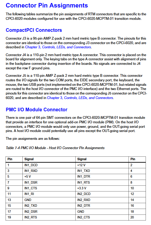
PMC slot: 1 32/64 bit PMC slot (J11-J14), supports 33/66MHz rate, supports PIM module expansion I/O function, PMC user I/O signals are routed to the transition module through J3/J5 connectors;
EIDE interface: Supports primary (for connecting to CompactFlash) and secondary (for connecting to external devices) channels, supports PIO accelerated transfer and DMA mode, and complies with ATAPI standards;
Local resources
Timer/Watchdog: Each dual Harrier ASIC contains 2 32-bit programmable timers (1 μ s resolution) and 2 independent watchdogs (timeout can trigger reset or interrupt); M48T37V includes one programmable timer that triggers a hard reset upon timeout;
I2C bus: supports 2 I2C main interfaces, interfaces with Serial EEPROM (VPD storage), SPD memory configuration chips, etc., with programmable communication speed;
Interrupt Controller: MPIC (Multi Processor Interrupt Controller) supports 8 programmable hardware interrupts, supports level/edge triggering, and has configurable interrupt priority;
High availability (HA) feature: supports system slot hot plugging (requires HA chassis), and achieves hot plugging detection through BD_SEL # and HEALTHY # signals; Support bus redundancy arbitration and dual Harrier collaboration to ensure stable system operation.
Safety and Compliance
Safety operation regulations: The equipment has lethal high voltage, and grounding is required during operation. ESD protective equipment must be used, explosive environments are prohibited, unauthorized disassembly of the cover plate is prohibited (only authorized personnel can disassemble the machine), single person maintenance is prohibited, and software must be closed before hot plugging;
EMI compliance: As an A-class digital device, it needs to be used in a compliant chassis. The core requirements include shielding wires for external I/O ports, grounding of cable shielding layers, grounding of chassis rails, and tightening of panel screws. Otherwise, it may result in excessive RF emissions;
Cooling requirement: 250 LFM forced air cooling is required at 55 ℃ environment, with CPU as the main heat source, ensuring smooth heat dissipation channels; Avoid adjacent installation of high-power modules and increase airflow in high-temperature environments;
Data security: Before reprogramming Flash, it is necessary to back up the firmware to avoid overwriting PPC bugs; Before hot plugging modules, it is necessary to shut down the operating system and applications to prevent data corruption or file system crashes;
Environmental compliance: Complies with RoHS 6/6 standards, prohibits harmful substances such as lead and mercury; Abandoned modules must be disposed of in accordance with local regulations.
Supporting resources
Firmware: PPCBug debugging firmware (including debugging and diagnostic functions), supporting memory read and write, breakpoint debugging, assembly/disassembly, self-test, etc; Provide a rich command set (such as MD memory display, GO executable program, HE help), support CNFG/ENV command configuration of system parameters;
Software: Supports VMEexec driver package, USB 2.0 driver, EIDE driver, Floppy controller driver, etc; Compatible with third-party PowerPC architecture applications, available through Motorola sales offices;
Related documents: MPC7410 user manual, Harrier ASIC programming guide, PPCBug firmware user manual, RAM500 module manual, CPCI-6020 programming reference guide, as well as industry standard documents such as CompactPCI, PCI, ISA, etc;
Technical support: The connector signal definition, parts list, and schematic diagram of CPCI-6020 can be obtained through Motorola sales office, and are provided free of charge; Support RISCWatch debugging interface and Mictor debugging connector for easy hardware debugging.
- YOKOGAWA
- Reliance
- ADVANCED
- SEW
- ProSoft
- WATLOW
- Kongsberg
- FANUC
- VSD
- DCS
- PLC
- man-machine
- Covid-19
- Energy and Gender
- Energy Access
- Renewable Integration
- Energy Subsidies
- Energy and Water
- Net zero emission
- Energy Security
- Critical Minerals
- A-B
- petroleum
- Mine scale
- Sewage treatment
- cement
- architecture
- Industrial information
- New energy
- Automobile market
- electricity
- Construction site
- HIMA
- ABB
- Rockwell
- Schneider Modicon
- Siemens
- xYCOM
- Yaskawa
- Woodward
- BOSCH Rexroth
- MOOG
- General Electric
- American NI
- Rolls-Royce
- CTI
- Honeywell
- EMERSON
- MAN
- GE
- TRICONEX
- Control Wave
- ALSTOM
- AMAT
- STUDER
- KONGSBERG
- MOTOROLA
- DANAHER MOTION
- Bentley
- Galil
- EATON
- MOLEX
- Triconex
- DEIF
- B&W
- ZYGO
- Aerotech
- DANFOSS
- KOLLMORGEN
- Beijer
- Endress+Hauser
- schneider
- Foxboro
- KB
- REXROTH
- YAMAHA
- Johnson
- Westinghouse
- WAGO
- TOSHIBA
- TEKTRONIX
- BENDER
- BMCM
- SMC
- HITACHI
- HIRSCHMANN
- XP POWER
- Baldor
- Meggitt
- SHINKAWA
- Other Brands
- UniOP
- KUKA
- IBA
- Beckhoff
- ADLINK
-
Beckhoff CP6500-1012-0060 - Control Cabinet PC Interface Unit
-
Beckhoff FC5202-0000 - 2-Channel DeviceNet Master PCI Interface Card
-
Beckhoff CP6606-0001-0020 - 7-Inch Economy Panel PC Touch
-
Beckhoff CP2921-0010 - Multi-Touch Integrated Control Panel Display
-
Beckhoff CP7802-0001-0010 - 15-Inch Touch Screen Control Panel HMI
-
Beckhoff C6920-0050 - Control Cabinet Industrial PC
-
Beckhoff BK9105 - EtherNet/IP Bus Coupler Network Interface
-
Beckhoff 31 Modules - Bus Terminal Slice I/O Lot Assortment
-
Beckhoff CX2020-0120 - Embedded PC Basic CPU Module 8GB CFast Card
-
Beckhoff CP7001-0000 - HMI Control Panel Touch Screen
-
B&R 7EX484.50-1 - System 2005 Controller Base Module Slots
-
Beckhoff EK1322 - 2-Port EtherCAT P Extension Feed-In Terminal
-
Beckhoff CP6606-0001-0020 - 7-Inch Single-Touch Economy Panel PC
-
Beckhoff CP6607-0001-0000 - Economy Installation Operator Panel PC 5.7-Inch
-
Beckhoff AX5103-0000-0200 - Digital Compact Servo Driver 3 Phase
-
Beckhoff CP7802-0001-0010 - 15-Inch Touch Screen Control Panel
-
Beckhoff AX8620 - Power Supply Module Axis System
-
Beckhoff CX2030-0121 - Embedded PC Controller Module
-
Beckhoff CP6606-0001-0020 - 7-Inch Economy Panel PC Touch Screen
-
Beckhoff CX2030-0121 - Embedded PC CPU Module Windows Standard 7
-
Beckhoff BX3100-0000 - PROFIBUS DP Bus Terminal Controller
-
Beckhoff CX1020-0000 - Controller Set with Power Supply Unit
-
Beckhoff EK1100 - EtherCAT Coupler Terminal Module Set
-
Beckhoff CP7002-1043-0010 - HMI Display Panel with Control Panel Bracket
-
Beckhoff AM8031-0D10-0000 - Synchronous Servo Motor
-
Beckhoff CX5130-0175 - Embedded PC 4GB RAM Controller
-
Beckhoff CX5130-0155 - Embedded PC Automation Controller
-
Beckhoff C6930-0010 - Control Cabinet Industrial PC Core Duo
-
Beckhoff CP3924-0000 - Multi-Touch Control Panel Display
-
Beckhoff AM8023-0F20-0000 - Synchronous Servo Motor
-
B&R KL3362 - Bus Terminal Thermocouple Input Module
-
Beckhoff AL2006-0000-0000 - Linear Servo Motor Three Phase
-
Beckhoff CX5140-0155 - Embedded PC CPU Controller Module
-
Beckhoff FC9002 - Ethernet PCI Network Interface Card
-
Beckhoff CP7203-0021-0040 - Built-In Panel PC 19-Inch Touch Screen
-
Beckhoff C6930-0020 - Control Cabinet Industrial PC HDD CF Card
-
Beckhoff CX2900-0033 - Memory Card CFast Storage
-
Beckhoff CP6201-0001-0020 - Built-In Panel PC Display
-
b+m surface systems C6930-1121-0060 - Industrial PC Beckhoff Core i7
-
Beckhoff CP2221-0010 - Multi-Touch Built-In Panel PC
-
Beckhoff C6017-0010 - Ultra-Compact Industrial PC
-
Beckhoff FC5102-0000 - 2-Channel CANopen PCI Interface Card
-
Beckhoff CP7021-0000-0000 - HMI Control Panel Interface
-
Beckhoff CP2216-0020 - Multi-Touch Built-In Panel PC
-
Beckhoff C6140 - Industrial PC Tower System Pentium 4
-
Beckhoff AM3033-1E40 - Servo Motor with Gearbox Assembly
-
Beckhoff CX9020-0115 - Embedded PC CPU Controller Module
-
Beckhoff CP6809-0001-0000 - Built-In Control Panel HMI Terminal
-
Beckhoff CP3919-0000 - Multi-Touch Control Panel Touchscreen Monitor
-
Beckhoff AM8053-0LHB-0000 - Synchronous Servo Motor
-
Beckhoff C6920-1028-0000 - Control Cabinet Industrial Computer PC
-
Beckhoff CX1100-0014 - Power Supply Unit for CX1030
-
Beckhoff CX9001-0101 - Embedded PC CPU Controller Module
-
Beckhoff CP3916-1428-0000 - Control Panel Multi-Touch Monitor
-
Beckhoff CP7037-1027-0010 - HMI Built-In Control Panel PC
-
Beckhoff CX1020-0120 - CPU Module DVI USB Windows Standard
-
Beckhoff CX5020-0121 - Embedded PC Controller Module
-
Beckhoff EL5042 - 2-Channel Encoder Interface BiSS C EtherCAT Terminal
-
Beckhoff CP7201-0021-0040 - Built-In Panel PC Touch Monitor
-
B&R X20-RT-8401 - reACTION Technology Module I/O Block
-
Beckhoff CP2915-0010 - HMI Control Panel Display Touch Screen
-
Beckhoff EL7221 - Servomotor Cyber Terminal EtherCAT Module
-
Beckhoff CX5140-0175 - Embedded PC CPU Module
-
Beckhoff C6017-0010 - Ultra-Compact Industrial PC
-
Beckhoff CX2020-0130 - Embedded PC Basic CPU Module
-
Beckhoff CX1030-0011 - Basic CPU Module Windows CE 6.0
-
Beckhoff AM8043-1E00-0000 - Synchronous Servo Motor
-
Beckhoff CX1020-0110 - CPU Module Controller Interface Bundle
-
Beckhoff C6930-1069-0030 - Control Cabinet Industrial PC Mainboard CB3054-0001
-
Beckhoff KL9528 - Power Supply Terminal Module
-
Beckhoff AM8053-0K20-0000 - Synchronous Servo Motor
-
Beckhoff CX5020-1111 - Embedded PC Controller Module
-
Beckhoff CX5130-0175 - Embedded PC CPU Module Intel Atom
-
Beckhoff CP6401-1024-0040 - Husky Display Control Panel HMI Terminal
-
Beckhoff CP2616-0000 - Multi-Touch Display Automation Panel PC
-
Beckhoff CP7921-1075-0000 - 12-Inch HMI Control Panel ELO Touch
-
Beckhoff C6930-0060 - Control Cabinet Industrial PC SSD
-
Beckhoff AX5112-0000 - Digital Compact Servo Drive 3 Phase
-
Beckhoff C6930-0040 - Control Cabinet Industrial PC Intel Core i5
-
Beckhoff CP2616-0000 - Multi-Touch Display Automation Panel PC
-
Beckhoff KL1414 - 4-Channel Digital Input Bus Terminal
-
Beckhoff CX1020-0000 - Basic CPU Module Controller
-
Beckhoff CP6201-1008-0000 - 12-Inch Built-In Panel PC
-
Beckhoff CP7021-0000 - HMI Control Panel Display Screen
-
Beckhoff AX5106-0000 - Digital Compact Servo Drive
-
Beckhoff BX3100-0000 - Profibus DP Bus Terminal Controller
-
Beckhoff CP2916-0000 - Multi-Touch Built-In Control Panel
-
Beckhoff C6925-0030 - Fanless Control Cabinet Industrial PC
-
Beckhoff C6330 - Industrial PC Motherboard Boser HS6237 Celeron
-
Beckhoff AM3033-0C00-0000 - Synchronous Servo Motor
-
Beckhoff CP7232-0001-0030 - Control Panel PC HMI
-
Beckhoff CX5020-0122 - Embedded PC CPU Module
-
Beckhoff AM8043-0H10-0000 - Rotary Synchronous Servo Motor
-
Beckhoff CP3924-0010 - Multitouch Control Panel HMI
-
Beckhoff CX9020-0110-1005 - Embedded PC Basic CPU Module
-
Beckhoff BK9105 - EtherNet/IP Bus Coupler
-
Beckhoff CX1500-M310 - Profibus Master Fieldbus Extension Module
-
Beckhoff CX1500-M510 - PROFIBUS Master Fieldbus Extension Module
-
Beckhoff CP9922.0 - TTL-TX Display Transmitter Card
-
Beckhoff CP9010_1 - ISA Slot Interface Card
-
Beckhoff NRL75-DC30S15B - LCD Inverter Board
-
Beckhoff LTD121C30S - Toshiba LCD Display Panel
-
Beckhoff CP7732-1207-0030 - Operating Terminal Panel PC HMI
-
Beckhoff C5102-0010 - Rackmount Industrial Computer PC5000
-
Beckhoff C6015-0010 - Ultra-Compact Industrial PC
-
Beckhoff CB1056-0001 - Industrial PC Motherboard Mainboard
-
Beckhoff AX5103 - Digital Compact Servo Amplifier 1 Axis
-
Beckhoff AM8052-0J00-9000 - Rotary Synchronous Servo Motor
-
Beckhoff CP7932-0002-0000 - Control Panel HMI Display
-
Beckhoff CB1061-0001 - Industrial PC Motherboard Mainboard
-
Beckhoff C5102-0060 - 19-inch Rackmount Industrial PC
-
Beckhoff EL7342 - 2 Channel DC Motor Motion Interface EtherCAT Terminal
-
Beckhoff CX5120-0135 - Embedded PC CPU Module Intel Atom
-
Beckhoff CB1061-G4 - Industrial PC Motherboard Mainboard
-
Beckhoff CX50100121 - Embedded PC CPU Module
-
Beckhoff CX1030-0013-1002 - Basic CPU Module Intel Pentium M
-
Beckhoff CP7802-1075-0010 - Control Panel Touch Screen HMI
-
Beckhoff AM8023-0E20-0000 - Rotary Synchronous Servo Motor
-
Beckhoff EL5032 - 2 Channel Encoder Interface EnDAT EtherCAT Terminal
-
Beckhoff CX5130-0175 - Embedded PC CPU Module Intel Atom
-
Beckhoff CA4040-0000 - PCI Ethernet Network Board
-
Beckhoff C3340 - Panel PC Industrial Workstation
-
Beckhoff EL3068 - 8 Channel Analog Input EtherCAT Terminal 0-10V
-
Beckhoff EL1889 - 16 Channel Digital Input EtherCAT Terminal
-
Beckhoff C6640-0050 - Control Cabinet Industrial PC Intel Core i7
-
Beckhoff PC MIC 3230 TP - Industrial Panel PC Touch Screen
-
Beckhoff CX2040-0135 - Embedded PC Industrial CPU Module
-
Beckhoff CP6202-1020-0010 - Built-in Panel PC HMI

K-JIANG

Add: Jimei North Road, Jimei District, Xiamen, Fujian, China
Tell:+86-15305925923