
K-WANG


YASKAWA MP2000 series machine controller communication module
YASKAWA MP2000 series machine controller communication module
The entire process of starting the communication module
Step 1: Prepare using the machine
Essential equipment: MP2000 series controller, communication module, communication partner device, dedicated cable, computer with MPE720 installed
Controller compatibility: MP2200 (JEPMC-BU2200/BU2210, maximum of 8 modules), MP2300 (JEPMC-MP2300, maximum of 3 modules), MP210M (JAPMC-MC2140, expansion board required, maximum of 8 modules), MP2500MD (JEPMC-MP2540-D , expansion board required, maximum of 8 modules)
Step 2: Module installation and disassembly
Installation steps: Power off → Remove the machine controller battery cover → Remove the optional module cover → Align the guide rail and insert the module → Install the cover → Power on
Disassembly steps: Power off → Backup program → Remove cable → Remove battery cover → Remove cover → Use battery cover protrusion to pry module → Pull out module
Step 3: Communication Manager Settings
Supported port types: Serial (RS-232C), Ethernet, Ethernet (LP), CP-215
Key setting example (Ethernet): Set the computer IP to 192.168.1.2 and subnet mask to 255.255.255.0; Set the Logical PT to Ethernet and fill in the computer IP address for the Communication Manager
Step 4: Automatic Configuration Execution
Trigger method: Set "CNFG" to ON and restart MP2200/MP2300; MP210M/MP2500MD operated through the MPE720 menu
Result difference:
CNFG Initiate Results
The ON module has been updated, and all communication modules are configured according to default settings
The ON/OFF module has been updated, with existing modules retaining their configuration and new modules using default settings
Step 5: MPE720 Startup and Transfer Definition
Ver.6: Online → Communications Setting → Select Logical Port → Set Parameters
Ver.5.xx: Start MPE720 → Open PLC folder → Properties → Network → Check OnLine → Select logical port
Transfer definition: Open the module composition definition screen → double-click the corresponding module → set parameters → save to flash memory

Detailed explanation of transmission mode and protocol
Classification of transmission modes
Mode applicable communication mode (module) core characteristics
Information transmission RS-232C (all), Ethernet (218IF-01/02), MPLINK (215AIF-01) event triggered, using MSG-SND/MSG-RCV functions
Engineering transmission RS-232C (all), Ethernet (218IF-01/02), MPLINK (215AIF-01) panel commands+MPE720 for program transmission
Link Transport MPLINK (215AIF-01) regularly sends and receives, only supported by 215AIF-01
Core Communication Protocol
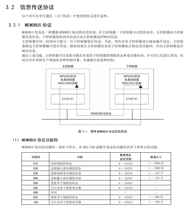
MEMOBU: Yaskawa standard, main controller specifies sub controller address communication, function codes include 01H (read winding), 03H (read hold register), etc., supporting 1-2000 bits (bit data), 1-125 words (word data)
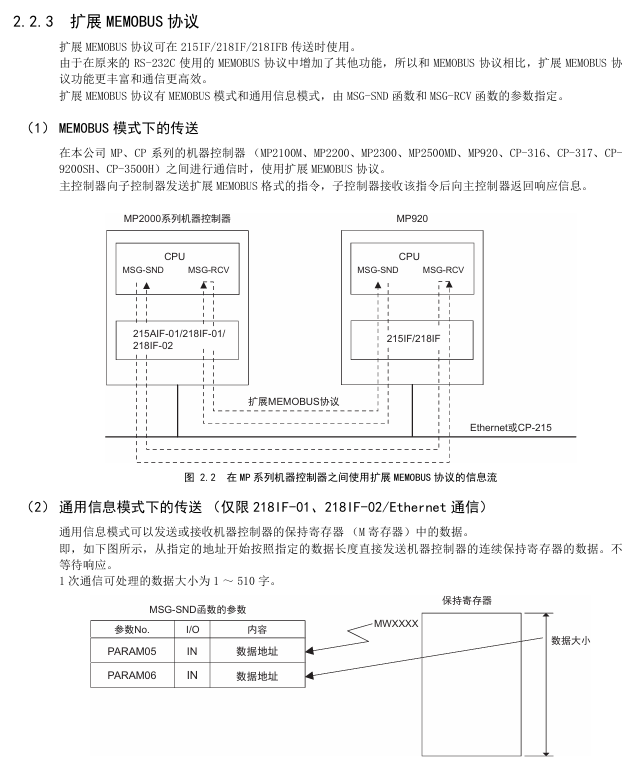
Extended MEMOBU: MEMOBU extension, adding function codes such as 09H (extended read hold register), transmitting 1-508 words at once, supporting MEMOBU/general information mode
MELSEC: Compatible with Mitsubishi A-series, supports communication between CPUs and fixed buffer communication, with function codes corresponding to ACPU universal commands (such as WR → 01H/02H)
MODBUS/TCP: Industrial Ethernet protocol, supports 1-2000 bits (read winding), 1-125 words (read register), 218IF-01/02 automatic conversion protocol
No steps: Directly transfer data from the M register, divided into word (1-254 words) and byte (1-508 bytes) units, with no response
Serial communication (taking 217IF-01 as an example)
Ports and protocols
Interface: RS-232C (PORT, 9-pin), RS-422/485 (14 pin)
Supporting protocols: MEMOBU, MELSEC, OMRON, Stepless, Stepless FD (Full Duplex, Maximum Received 5080 Words)
Transmission definition parameters
Example of Parameter Setting Content
Transmission Protocol MEMOBU/MELSEC/OMRON/Stepless MEMOBU
Master (Address 0)/Slave (Address 1~63) Slave, Address 1
Baud rate 9600/19200bps 19200bps
Data length 7/8 bits 8 bits
Parity Even/Odd/None Even
Connection Example
Connected to MELSEC: RS-232C (pin 2=TXD, 3=RXD) of 217IF-01 connected to Mitsubishi AJ71UC24 (pin 2=RXD, 3=TXD), MELSEC set station number 01, baud rate 19200bps
Connected to frequency converter: RS-485 (pin 3=RX+, 4=RX -, 8=TX+, 9=TX -) of 217IF-01 is connected to VS-616G5, and frequency converter H5-01=1 (address) H5-02=9600bps
Key module characteristics (218IF-01/02, 260IF-01)
218IF-01 module
Interface: RS-232C (PORT), Ethernet (10Base-T, RJ45)
Specification: Ethernet transmission speed of 10Mbps, half duplex; RS-232C maximum transmission 15m
Ethernet settings: IP address (default 192.168.1.1), subnet mask, connection parameters (TCP/UDP, ports 256~65535)
218IF-02 module
Interface: RS-232C (PORT), Ethernet (100Base TX/10Base-T)
Advantages: Supports Ethernet (LP) ports, higher engineering communication speed, maximum transmission of 100m (100Base TX)
260IF-01 module
Communication: DeviceNet, supports Explicit protocol, main controller settings
Specification: Maximum number of nodes 64, transmission speed 125/250/500kbps
Key issues
Question 1: There are two triggering methods for the automatic configuration of MP2000 series communication modules. Which controllers are they applicable to? What are the differences in configuration results?
Answer:
Applicable controllers:
Dial switch trigger: suitable for MP2200 and MP2300, triggered by turning on the "CNFG" toggle switch of the machine controller and restarting the power supply;
MPE720 operation trigger: applicable to MP210M and MP2500MD. After starting MPE720, select Order → Self Configure All Modules/Module Self Configuration on the Module Configuration screen to trigger.
Differences in configuration results:
Specific operation results of triggering method
The dip switch (MP2200/MP2300) CNFG=ON, Initiate=ON module composition definition is updated, and all detected communication modules are configured according to default values
The dip switch (MP2200/MP2300) CNFG=ON and Initialize=OFF modules constitute a definition update. Modules that already have transmission definitions retain their current definitions, while newly detected modules use default values
MPE720 (MP210M/MP2500MD) automatically configures all module composition definitions and updates them. Existing defined modules retain their current definitions, while newly detected modules use default values
MPE720 (MP210M/MP2500MD) automatically configures a single module with only selected module configurations and transmission definitions. Existing definitions are reserved, and newly detected ones use default values
Question 2: What are the core differences in functionality and usage between the IF-01 module, which supports two protocols: Stepless and Stepless FD?
Answer: The core differences between the two are reflected in communication methods, number of channels, data processing capabilities, etc., as follows:
Comparing dimensions without steps or steps FD
Communication method: Half duplex (cannot transmit/receive simultaneously), Full duplex (can transmit/receive simultaneously)
1 information channel (MSG-SND/MSG-RCV dual-use) 2 channels (1 dedicated for sending and 1 dedicated for receiving)
The maximum data size for both sending and receiving is 254 words. Sending 254 words and receiving a maximum of 5080 words (20 buffers, each buffer containing 508 words)
Data exception handling: If one byte in one message is abnormal, all data will be discarded. Only the abnormal byte will be discarded, and normal data will be retained. The exception will be reported to the MSG-RCV function
Wiring requirements: Half duplex wiring (such as RS-485 2-wire system), full duplex wiring (such as RS-485 4-wire system, separate transmission/reception lines)
Suitable for simple one-way communication scenarios that require high-speed simultaneous transmission and reception, such as real-time data acquisition and control
Channel number setting: MSG-SND/MSG-RCV are both set to 1. MSG-SND is set to 1, and MSG-RCV is set to 2
Question 3: The Ethernet communication of the IF-01 module supports two connection types, TCP and UDP. How to choose? What are the precautions for using these two types under a step-by-step protocol?
Answer:
Selection criteria for connection type:
TCP: a connection type protocol that requires the establishment of a connection, supports data confirmation, error retransmission, flow control, and has high communication quality. It is suitable for scenarios that require high data reliability, such as control instruction transmission;
UDP: A connectionless protocol that does not require establishing a connection, has simple processing, fast communication speed, and is suitable for scenarios that require high real-time performance and can tolerate a small amount of data loss (such as real-time status monitoring).
Notes under the Stepless Protocol:
Attention to TCP usage:
TCP is a byte stream protocol, and continuous transmission of data may result in the synthesis of data packets. The receiving side cannot recognize the data boundary and measures need to be taken (such as setting a transmission interval of more than 1 second, establishing command response protocols, and avoiding packet segmentation);
Each connection only has one receive buffer, and before receiving data, the MSG-RCV function is used to read out old data to avoid new data overwriting old data.
UDP usage precautions:
No connection confirmation, sending to a non-existent socket will result in an error. It is necessary to ensure that the other party's device is online and the port is correct;
The receiving interval should be greater than twice the execution period of the MSG-RCV function (if the function period is less than 5ms, the sending interval should be set to 12ms or more) to avoid data coverage.
- YOKOGAWA
- Reliance
- ADVANCED
- SEW
- ProSoft
- WATLOW
- Kongsberg
- FANUC
- VSD
- DCS
- PLC
- man-machine
- Covid-19
- Energy and Gender
- Energy Access
- Renewable Integration
- Energy Subsidies
- Energy and Water
- Net zero emission
- Energy Security
- Critical Minerals
- A-B
- petroleum
- Mine scale
- Sewage treatment
- cement
- architecture
- Industrial information
- New energy
- Automobile market
- electricity
- Construction site
- HIMA
- ABB
- Rockwell
- Schneider Modicon
- Siemens
- xYCOM
- Yaskawa
- Woodward
- BOSCH Rexroth
- MOOG
- General Electric
- American NI
- Rolls-Royce
- CTI
- Honeywell
- EMERSON
- MAN
- GE
- TRICONEX
- Control Wave
- ALSTOM
- AMAT
- STUDER
- KONGSBERG
- MOTOROLA
- DANAHER MOTION
- Bentley
- Galil
- EATON
- MOLEX
- Triconex
- DEIF
- B&W
- ZYGO
- Aerotech
- DANFOSS
- KOLLMORGEN
- Beijer
- Endress+Hauser
- schneider
- Foxboro
- KB
- REXROTH
- YAMAHA
- Johnson
- Westinghouse
- WAGO
- TOSHIBA
- TEKTRONIX
- BENDER
- BMCM
- SMC
- HITACHI
- HIRSCHMANN
- XP POWER
- Baldor
- Meggitt
- SHINKAWA
- Other Brands
- UniOP
- KUKA
- IBA
- Beckhoff
-
LTI SC52.0040.0012.0000.0 - Servo Drive
-
Lti SC52.0040.0012.0000.0 - Servo Drive
-
Milton Industries LTI Tool By Milton LT1240 - 1/2" Drive Lugnut Remover
-
LTi Drives SO84.200.P030.0000.0-W - Servo Spindle Drive
-
LTI DRIVES LSP08-035-320-30-B0R1PY170 - Servo Motor
-
LTI DRIVES SE84.200.SC00.0001.0-W - Servo Drive
-
Lust CDE34.005.W2.2 - Lti Drives Controller
-
LTi SO84.012.0030.0011.2 - ServoOne Servo Drive
-
LTi Drives SO CM-P.0010.11.00.0 - Servo Drive Controller
-
LTi CDE34.017.W3.0 - Servo Drive
-
LTI Drives CDB32.004, C2.0,SH - Positioning Controller
-
LUST CM-CAN1 - LTi DRIVES Communication Module
-
LTi SO84.012.1030.0000.2 - Servo Drive
-
LTI MOOG CDE54.044 - PITCHMASTER FREQUENCY CONVERTER 181-01019
-
MOOG LTI 181-01019 CDE54.044 - PITCHMASTER FREQUENCY CONVERTER
-
Lust LTi Drives CDE34.010,D2.0 - Servo Drive Controller
-
LTI SO84.032.0003.0101.2 - Servo Drive
-
Seagate 9CC132-302 Harris LTI-CS IRT-34-0021-01 - Hard Drive 160GB
-
LTI SO84.032.0003.0001.2 - Servo Drive
-
LTI SO24.007.0070.0000.1 - SERVO CONTROLLER
-
LTi drive CDA32.003.C3.0.H05-01.PC1 - Servo Drive
-
LTI SO84.016.0030.0000.2 - SERVO CONTROLLER
-
LUST LTI CD A34.008,W1.4, BR - SERVO DRIVE
-
MOOG LTI 181-01019 CDE54.044 - PITCHMASTER FREQUENCY CONVERTER
-
LTI MOOG 181-01019 - PITCH Master Servo Drive CDE54.044
-
LTI SERVO ONE SO84.045.0030.0001.2-W - Drive
-
LUST LTi SO84.032.0040.0000.2 - SERVO ONE DRIVE
-
LTi Drives LSH-074-2-30-3 20/T1,G6.1M - SERVO MOTOR
-
LTI SO84.016.0000.0101.2 - servo drive
-
LTI SA54.0550.0033.0000.0 - Servo Drive
-
LTI SA54.0550.0033.0000.0 - Servo Drive
-
LTI LT 4850 - 3/8" Drive 3-Pc Twist Socket Transmission Drain Plug Removal System
-
LTI Tools LT4400-30 Lock Technology - 3/4" Twist Socket 1/2" Drive Lugnut Remover
-
LTI Tools LT-1400C - 1/2 Drive Wheel Torque Extension Tool
-
LTI Tools LT1250 - 1/2" Drive Dual Sided Socket Lug Nut Remover Tool
-
LTI SO84.032.0003.0101.2 - Servo Drive
-
LTI MOOG 181-01019 - PITCH Master Servo Drive CDE54.044
-
MOOG LTI 181-01019 CDE54.044 - PITCHMASTER FREQUENCY CONVERTER
-
MOOG LTI 181-01019 CDE54.044 - PITCHMASTER FREQUENCY CONVERTER
-
MOOG LTI 181-01019 CDE54.044 - PITCHMASTER FREQUENCY CONVERTER
-
LTI SA54.0550.0033.0000.0 - Servo Drive
-
LTI Tools LT-4800 - 7 Piece Twist Socket 3/8" Drive Oil Drain Plug Removal Set
-
LTI SA54.0550.0033.0000.0 - Servo Drive
-
LTI Drive SO24.007.00300000.0 - Servo Drive
-
LTI TOOLS LTI 1400-I - Drive Wheel Torque Extension
-
LTI Tools LT4400-3 - 3/4" 19mm Twist Socket 1/2" Drive Lugnut
-
LTI TOOLS LTI 1400-BB - Drive Wheel Torque Extension
-
LTI SO84.032.0003.0101.2 - Servo Drive
-
LTI Tools LT-4512 - 3/8" Drive 12mm Twist Socket
-
LTI MOTION Luster SO84.032.0003.0001.2 - Servo Drive
-
LTI Tool By Milton LT1600P - 1" Drive Torx Stick
-
LTI Lust VF1424L,HF,OP2,S56 - Variable Frequency Drive
-
LUST CDA32.004,C1.4,H08,B0 - SERVO DFRIVE CM-CAN1 Module
-
LTI SO84.045.0002.0001.2-W - Drive
-
LTI Lust VF1404M,C9,PT1,BR1 - Inverter Type VF1404M
-
LTI SA54.0550.0033.0000.0 - Servo Drive
-
LTI Tools LT-1400C - 1/2" Drive Wheel Torque Extension
-
Lust LTI DRiVES CDA32.006, C3.0, H09 - Variateur De Fr茅quence Frequency Inverter
-
LTI MOOG CDE54.044 - PITCH master SERVO DRIVE
-
LTI MOOG CDE54.044 - PITCH master SERVO DRIVE
-
LTI SO84.143.0020.0101.2-W - servo drive
-
LTI MOTION SC34.0200.0011.0000.0 - Servo drives
-
LTI SO84.032.0003.0001.2 - Servo Drive
-
LTI DRIVES GmbH MS100 - Assembly Set Mounting Kit
-
LTI SO84.032.0003.0001.2 - Servo Drive
-
LTI SO84.032.0003.0001.2 - Servo Drive
-
LTI MOTION SO84.032.0003.0101.2 - servo drive
-
LTI SO84.032.0003.0101.2 - Servo Drive
-
LTI MOOG CDE54.044 - PITCH master SERVO DRIVE
-
LTI MOTION CDE32.004.C2.4 - Servo drives
-
LTI CDD34.032锛學x.x锛孊R锛孭C1 - Servo Drive
-
Lust LTI DRiVES CDA32.006, C3.0, H09 - Inversor De Frecuencia Frequency Inverter
-
Lust SO84.008.0030.1000.0 - Servo One LTi Drive
-
LTI MOTION SO84.032.0003.0101.2 - Servo drives
-
LUST LTi CDA32.004,C1.4 - SERVO DRIVE
-
LTI MOOG CDE54.044 - PITCH Master SERVO DRIVE
-
LTI KEBA CDB32.004 C2.7, SH - PN: 08673530 Frequency Inverter
-
LTI Tools LT-1400C - 1/2" Drive Wheel Torque Extension
-
LTI LT1400-E - 1/2" Drive Wheel Torque Extension
-
LTI MOOG 181-01019 - PITCH master SERVO DRIVE CDE54.044
-
LTI LSN-097-0510-30-560/T1 - Actuator Motor
-
LTI Tools LT 4800 - 7 Piece 3/8" Drive Twist Socket Oil Drain Plug Removal System
-
LTI DRIVES GmbH MS100 - MONTAGESET Assembly Set Mounting Kit
-
Lti SC52.0040.0012.0000.0 - Servo Drive
-
LTI DRIVES GmbH MS100 - Juego De Montaje Assembly Set Mounting Kit
-
LTi DSM4-14.2-21R83-200 - Drives servomoteur Servo Motor
-
MOOG CDE 54.044.GDA - Pitch Master Industrielle Turbine Lti Drive
-
LTI SO24.004.0030.1000.0 - Servo Drive Controller
-
Lti MOOG CDE54.044 - Pitch Master Servo Drive
-
Lust LTI DRiVES CDA32.006, C3.0, H09 - Inverter
-
LTI MOTION GMBH CDB34.006,W3.0,PC1,H39 - Frequency inverter
-
LTI SO84.032.0003.0001.2 - Servo Drive
-
MOOG CDE 54.044.D - Pitch Master Industrielle Turbine Lti Drive
-
LTI TOOLS LT-1460 - 1/2" DRIVE WHEEL TORQUE EXTENSION KIT 5 PIECE SET
-
Lust Cdb32.003, C2.4 - Lti Drives Servoregulador Frecuencia Servo Controller Inverter
-
Lust LTI DRIVES CDA32.006, C3.0, H09 - Frequency Inverter
-
Lust Lti SO82.004.0030.0000.2 - Servo Drive
-
LTI MOTION SC34.0200.0011.0000.0-SL - Servo drives
-
LTI MOTION SA54.0075.0033.0000.0 - Servo drives
-
LTI MOTION SC32.0075.1011.0000.0 - Servo drives
-
LTI Servo-One Junior SO22.006.0080.1000.0 - Servo Controller Servoregler
-
LUST CDA32.004, C1.4, H08, B0 - Servo Drive & LTI CM-CAN1 Module
-
LTI DRIVES LSP08-035-320-30-B0R1PY170 - Servo Motor
-
LUST LTI CDA32.004,C1.4.H08.B0 - SERVO CONTROLLER DRIVES
-
LUST LTi DRiVES CDS44.072LC1.2 - Servo Drive
-
Lti Servo-One Junior SO22.006.0082.1000.0 - Servo Controller Servoregler
-
LUST CDA32.008,C2.0,HF - Lti DRIVES Spindle Drive Inverter
-
LTI SO22.003.0082.0000.0 - Servo Drives One junior Servo Controller Servoregler
-
Lust Lti Drives CM-CAN1 - Communication Module
-
LUST Lti Drives Vf1202s, G8, I6 - Frequency Inverter Drive
-
LTI DRIVES BR-090.03.540.UR.H38 - Bremswiderstand Brake Resistor
-
LTi DRIVES PM-E40.2DRA054P - Wind Turbine Pitch Control Inverter
-
LTi Drives GmbH br-110.01.540-UR - Brake Resistor
-
LTI Drives LSN-097-0960-30-0560/T1,S4,B - Servo Motor
-
LUST CDA34.006.C2.0 - LTI Drives Servoregler
-
LUST LTI DRIVES SERVO ONE JUNIOR SO24.002.0020.0000.1 - Servo Drive Controller
-
LTI MOTION SO84.032.0003.0001.2 - Servo drives
-
LTI DDTD750V2-120 - IBOP ACTUATOR CYLINDER FOR TOP DRIVE
-
LTI CDE32.004, C2.4 - SERVO DRIVE
-
LUST LTI DRIVES CDD34.017 W3.4PC1 - Servo Drive Controller
-
LTI CDA3208,C3,0,HF - AC SERVO DRIVE
-
LUST LTI DRIVES LSH-074-3-30-560/T1,G6.1S - SERVO MOTOR
-
LUST Lti CDB32.004.C2.4.SH - AC Servo Drive
-
LTi CDA32.006, C3.0, H09 - Servo Drive
-
LTI SO22.003.0010.0000.0 - Servo Drive Servo one junior Servoregler Controller
-
LTi Drives DSM4-14.2-21R83-200 - Servo Motor
-
LUST Lti Drives Lsh-097-1-30-560/T1, 1R - Servomotor
-
LTI 1237 - 7 Piece 1/2" Drive Flip Socket Set

K-JIANG

Add: Jimei North Road, Jimei District, Xiamen, Fujian, China
Tell:+86-15305925923