
K-WANG


Hirschmann MS20/MS30 series industrial Ethernet switches
Hirschmann MS20/MS30 series industrial Ethernet switches
Overview
The installation user manual for Hirschmann MS20/MS30 series industrial Ethernet switches (Release 14 03/2023 version) covers four major modules: equipment overview, safety specifications, installation process, basic configuration, maintenance, and technical parameters. It provides detailed instructions on the hardware composition of the equipment (basic module, media module, SFP transceiver, etc.), installation steps (DIN rail installation, wiring, DIP switch configuration), safety compliance requirements (ATEX, IECEx and other hazardous environment certifications), and technical parameters (power supply range of 18-60V DC, working temperature -40 ℃~+70 ℃, port type supporting 10/100/1000Mbit/s twisted pair/fiber ports). It also offers a global technical support channel to provide comprehensive guidance for equipment deployment and operation in industrial scenarios.
Equipment Overview
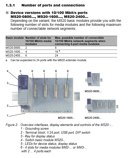
(1) Product classification and coding
Example of Port Configuration for Core Differences in Equipment Series
MS20 without Gigabit ports, modular design MS20-0800... 8 10/100Mbit/s ports
MS30 includes 2 Gigabit ports, modular design MS30-0802...: 8 10/100Mbit/s+2 1000Mbit/s ports
Product coding rules (15 digits): The first to fourth digits indicate the series (MS20/MS30), the sixth to seventh digits indicate the number of 10/100Mbit/s ports (08/16/24), the tenth digit indicates the temperature range (S: 0~60 ℃, T/E: -40~70 ℃), and the eleventh digit indicates the power supply range (A: 18-32V DC, C/E: 18-60V DC).
(2) Hardware composition
Basic module: including power terminals, DIP switches, USB/V.24 management interfaces, grounding screws, supporting 2 redundant power inputs (P1/P2).
Media module: Supports MM2 (10/100Mbit/s), MM3 (10/100Mbit/s with PTP), MM4 (1000Mbit/s Gigabit), MM22 (PoE port) and other series, with 2-4 ports, supporting twisted pair (RJ45/M12) and fiber optic (ST/LC/DSC) interfaces.
Expansion module: The MB20 expansion module can add 2 media module slots, suitable for MS20-1600/MS30-1602 models.
SFP transceiver: Supports Fast Ethernet/Gigabit Ethernet, including multimode (MM), single-mode (SM), and long haul (LH) types, with a maximum transmission distance of 176km (LH+type).
(3) Port type and function
Port type, speed, interface specifications, core functions
Twisted pair port 10/100/1000Mbit/s RJ45/M12 automatic negotiation, polarity switching AutoCrossing
Fiber optic port 100/1000Mbit/s ST/LC/DSC/MTRJ link monitoring, full duplex mode
PoE port 10/100Mbit/s RJ45 complies with IEEE 802.3af and supports Class 0-3 terminal power supply
AUI port 10Mbit/s Sub-D 15 pin supports SQE testing and DTE power monitoring
Safety regulations
(1) General safety requirements
Anti electric shock: The equipment casing is grounded, and sharp objects are prohibited from contacting the terminals. Only qualified personnel are allowed to operate.
Anti overheating: Keep the ventilation duct unobstructed, reserve a space of ≥ 10cm around the equipment, and avoid touching the casing during operation.
Fireproof: If the power supply does not meet the requirements of Class 2/LPS, it needs to be installed in a metal/flame-retardant plastic shell (V-1 level).
(2) Compliance with hazardous environments
Certification type applicable standard environmental parameters
ATEX EN IEC 60079-0/7/15 Temperature Class T4, Operating Temperature -40~+45 ℃
IECEx IEC 60079-0/7/15 Explosion proof Class II 3G Ex ec nC IIC T4 Gc
Class I Division 2 ANSI/ISA 12.12.01 Groups A-D, ambient temperature -40~+70 ℃
Special requirements: Only temporary connections to USB/V.24 interfaces are allowed in hazardous environments. The connector must be plugged and unplugged in a power-off state, and the signal contact current is limited to 100mA.
(3) Power supply and wiring safety
Power supply requirements: redundant input (P1/P2), DC power supply needs to be grounded to the negative pole, AC power supply needs to be isolated and grounded; Class 2 power supply is required in North America.
Wire specification: Copper wire (75 ℃), terminal supports up to 2.5mm ² (AWG 12) wire.
Shielding grounding: The shielding layer of twisted pair cables needs to be connected to the grounding terminal of the front panel of the equipment to avoid short circuits.
Installation process
(1) Preliminary preparation
Packaging inspection: Confirm the basic module, terminal block (4-pin/6-pin), label, and installation manual are included.
Label filling: Fill in the device name, MAC address, IP address, and other information and paste them on the surface of the device.
(2) Hardware installation steps
Media module/SFP installation: Remove the protective cap, align with the slot, insert and tighten the screws; The SFP transceiver needs to close the latch until it is securely fastened.
DIN rail installation: snap the sliding device onto the rail, press the bottom lock to fix it, and reserve a space of ≥ 10cm up and down.
Grounding: Grounded through DIN rails or dedicated grounding screws, with grounding wire specifications consistent with the power supply wire.
DIP switch configuration:
4-pin DIP switch (MS20/MS30 basic module): controls redundancy manager (RM), ring port selection, standby mode, and configuration priority.
3-pin DIP switch (MS20/MS30-... E...): The function is the same as a 4-pin switch, without a priority switch configured (all three keys are ON for software configuration).
(3) Wiring process
Power wiring: 4-pin terminals (P1/P2:+24V, 0V), 6-pin terminals (MS30-... E...: integrated power and signal contacts).
Signal contact wiring: Potential free relay contacts, supporting up to 1A/60V DC for remote diagnosis.
Data cable connection: Twisted pair cables should use Cat5e or above, and fiber optic cables should be matched with port types (SX/LX/LH) to avoid mixing.
(4) LED display configuration
Display mode switching: Press the "SELECT" button for ≥ 2 seconds to switch the port LED display meaning (link status, duplex mode, rate, etc.).
Device status LEDs: P1/P2 (power), RM (redundant), RUN (running), RL1/RL2 (signal contacts).
Basic configuration and maintenance
(1) Initial configuration
IP configuration method: Supports DHCP/BOOTP, V.24 interface (CLI), AutoConfiguration Adapter, HiView software.
Default account: admin (read-write permission, password private), user (read-only permission, password public). The password needs to be changed for the first login (≥ 8 characters, including uppercase and lowercase letters/numbers/special characters).
Core default settings: RSTP enabled, ring redundancy disabled, port auto negotiation enabled, V.24 baud rate 9600.
(2) Maintenance and disassembly
Daily maintenance: Regularly check relay contact resistance, software updates (downloaded from the official website), and clean ventilation ducts.
Disassembly steps: Disconnect the data cable → Cut off the power supply → Remove the terminal block → Press the guide rail lock to remove the device; SFP disassembly requires opening the latch and pulling it out.
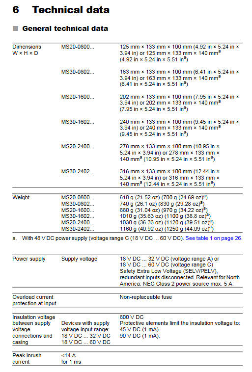
Core technical parameters
(1) Physical and environmental parameters
Specific indicators for parameter categories
Dimensions (W × H × D) MS20-0800:125 × 133 × 100~140mm
Weight 610g (MS20-0800)~1250g (MS30-2402)
Working temperature S-type: 0~60 ℃; T/E type: -40~70 ℃
Storage temperature -40~85 ℃
Protection level IP20
Pollution level 2
(2) Electrical parameters
Specific indicators for parameter categories
Power supply range A: 18-32V DC; C/E type: 18-60V DC
Power consumption MS20-0800: 5.0~7.4W; MS30-2402:12.6~18.0W
Signal contact maximum 1A (≤ 60 ℃)/100mA (60-70 ℃), 60V DC/30V AC
Insulation voltage 800V DC (power terminal and casing)
(3) Port transmission parameters
Port type maximum transmission distance support standard
1000Mbit/s twisted pair 100m IEEE 802.3ab
100Mbit/s multimode fiber (50/125 μ m) 5km IEEE 802.3u
1000Mbit/s single-mode fiber (9/125 μ m) 176km (LH+) IEEE 802.3z
PoE port 100m IEEE 802.3af
Accessories and Support
(1) Optional accessories
Accessory Type Example Model Usage
SFP transceiver M-SFP-LX/LC gigabit single-mode fiber transmission
Power adapter RPS60/48V EEC PoE module power supply
Terminal block 943 845-004 power/signal contact extension (50 pieces)
Configure adapter ACA22-USB local configuration and software updates
- YOKOGAWA
- Reliance
- ADVANCED
- SEW
- ProSoft
- WATLOW
- Kongsberg
- FANUC
- VSD
- DCS
- PLC
- man-machine
- Covid-19
- Energy and Gender
- Energy Access
- Renewable Integration
- Energy Subsidies
- Energy and Water
- Net zero emission
- Energy Security
- Critical Minerals
- A-B
- petroleum
- Mine scale
- Sewage treatment
- cement
- architecture
- Industrial information
- New energy
- Automobile market
- electricity
- Construction site
- HIMA
- ABB
- Rockwell
- Schneider Modicon
- Siemens
- xYCOM
- Yaskawa
- Woodward
- BOSCH Rexroth
- MOOG
- General Electric
- American NI
- Rolls-Royce
- CTI
- Honeywell
- EMERSON
- MAN
- GE
- TRICONEX
- Control Wave
- ALSTOM
- AMAT
- STUDER
- KONGSBERG
- MOTOROLA
- DANAHER MOTION
- Bentley
- Galil
- EATON
- MOLEX
- Triconex
- DEIF
- B&W
- ZYGO
- Aerotech
- DANFOSS
- KOLLMORGEN
- Beijer
- Endress+Hauser
- schneider
- Foxboro
- KB
- REXROTH
- YAMAHA
- Johnson
- Westinghouse
- WAGO
- TOSHIBA
- TEKTRONIX
- BENDER
- BMCM
- SMC
- HITACHI
- HIRSCHMANN
- XP POWER
- Baldor
- Meggitt
- SHINKAWA
- Other Brands
- UniOP
- KUKA
- IBA
- Beckhoff
-
LTI SC52.0040.0012.0000.0 - Servo Drive
-
Lti SC52.0040.0012.0000.0 - Servo Drive
-
Milton Industries LTI Tool By Milton LT1240 - 1/2" Drive Lugnut Remover
-
LTi Drives SO84.200.P030.0000.0-W - Servo Spindle Drive
-
LTI DRIVES LSP08-035-320-30-B0R1PY170 - Servo Motor
-
LTI DRIVES SE84.200.SC00.0001.0-W - Servo Drive
-
Lust CDE34.005.W2.2 - Lti Drives Controller
-
LTi SO84.012.0030.0011.2 - ServoOne Servo Drive
-
LTi Drives SO CM-P.0010.11.00.0 - Servo Drive Controller
-
LTi CDE34.017.W3.0 - Servo Drive
-
LTI Drives CDB32.004, C2.0,SH - Positioning Controller
-
LUST CM-CAN1 - LTi DRIVES Communication Module
-
LTi SO84.012.1030.0000.2 - Servo Drive
-
LTI MOOG CDE54.044 - PITCHMASTER FREQUENCY CONVERTER 181-01019
-
MOOG LTI 181-01019 CDE54.044 - PITCHMASTER FREQUENCY CONVERTER
-
Lust LTi Drives CDE34.010,D2.0 - Servo Drive Controller
-
LTI SO84.032.0003.0101.2 - Servo Drive
-
Seagate 9CC132-302 Harris LTI-CS IRT-34-0021-01 - Hard Drive 160GB
-
LTI SO84.032.0003.0001.2 - Servo Drive
-
LTI SO24.007.0070.0000.1 - SERVO CONTROLLER
-
LTi drive CDA32.003.C3.0.H05-01.PC1 - Servo Drive
-
LTI SO84.016.0030.0000.2 - SERVO CONTROLLER
-
LUST LTI CD A34.008,W1.4, BR - SERVO DRIVE
-
MOOG LTI 181-01019 CDE54.044 - PITCHMASTER FREQUENCY CONVERTER
-
LTI MOOG 181-01019 - PITCH Master Servo Drive CDE54.044
-
LTI SERVO ONE SO84.045.0030.0001.2-W - Drive
-
LUST LTi SO84.032.0040.0000.2 - SERVO ONE DRIVE
-
LTi Drives LSH-074-2-30-3 20/T1,G6.1M - SERVO MOTOR
-
LTI SO84.016.0000.0101.2 - servo drive
-
LTI SA54.0550.0033.0000.0 - Servo Drive
-
LTI SA54.0550.0033.0000.0 - Servo Drive
-
LTI LT 4850 - 3/8" Drive 3-Pc Twist Socket Transmission Drain Plug Removal System
-
LTI Tools LT4400-30 Lock Technology - 3/4" Twist Socket 1/2" Drive Lugnut Remover
-
LTI Tools LT-1400C - 1/2 Drive Wheel Torque Extension Tool
-
LTI Tools LT1250 - 1/2" Drive Dual Sided Socket Lug Nut Remover Tool
-
LTI SO84.032.0003.0101.2 - Servo Drive
-
LTI MOOG 181-01019 - PITCH Master Servo Drive CDE54.044
-
MOOG LTI 181-01019 CDE54.044 - PITCHMASTER FREQUENCY CONVERTER
-
MOOG LTI 181-01019 CDE54.044 - PITCHMASTER FREQUENCY CONVERTER
-
MOOG LTI 181-01019 CDE54.044 - PITCHMASTER FREQUENCY CONVERTER
-
LTI SA54.0550.0033.0000.0 - Servo Drive
-
LTI Tools LT-4800 - 7 Piece Twist Socket 3/8" Drive Oil Drain Plug Removal Set
-
LTI SA54.0550.0033.0000.0 - Servo Drive
-
LTI Drive SO24.007.00300000.0 - Servo Drive
-
LTI TOOLS LTI 1400-I - Drive Wheel Torque Extension
-
LTI Tools LT4400-3 - 3/4" 19mm Twist Socket 1/2" Drive Lugnut
-
LTI TOOLS LTI 1400-BB - Drive Wheel Torque Extension
-
LTI SO84.032.0003.0101.2 - Servo Drive
-
LTI Tools LT-4512 - 3/8" Drive 12mm Twist Socket
-
LTI MOTION Luster SO84.032.0003.0001.2 - Servo Drive
-
LTI Tool By Milton LT1600P - 1" Drive Torx Stick
-
LTI Lust VF1424L,HF,OP2,S56 - Variable Frequency Drive
-
LUST CDA32.004,C1.4,H08,B0 - SERVO DFRIVE CM-CAN1 Module
-
LTI SO84.045.0002.0001.2-W - Drive
-
LTI Lust VF1404M,C9,PT1,BR1 - Inverter Type VF1404M
-
LTI SA54.0550.0033.0000.0 - Servo Drive
-
LTI Tools LT-1400C - 1/2" Drive Wheel Torque Extension
-
Lust LTI DRiVES CDA32.006, C3.0, H09 - Variateur De Fr茅quence Frequency Inverter
-
LTI MOOG CDE54.044 - PITCH master SERVO DRIVE
-
LTI MOOG CDE54.044 - PITCH master SERVO DRIVE
-
LTI SO84.143.0020.0101.2-W - servo drive
-
LTI MOTION SC34.0200.0011.0000.0 - Servo drives
-
LTI SO84.032.0003.0001.2 - Servo Drive
-
LTI DRIVES GmbH MS100 - Assembly Set Mounting Kit
-
LTI SO84.032.0003.0001.2 - Servo Drive
-
LTI SO84.032.0003.0001.2 - Servo Drive
-
LTI MOTION SO84.032.0003.0101.2 - servo drive
-
LTI SO84.032.0003.0101.2 - Servo Drive
-
LTI MOOG CDE54.044 - PITCH master SERVO DRIVE
-
LTI MOTION CDE32.004.C2.4 - Servo drives
-
LTI CDD34.032锛學x.x锛孊R锛孭C1 - Servo Drive
-
Lust LTI DRiVES CDA32.006, C3.0, H09 - Inversor De Frecuencia Frequency Inverter
-
Lust SO84.008.0030.1000.0 - Servo One LTi Drive
-
LTI MOTION SO84.032.0003.0101.2 - Servo drives
-
LUST LTi CDA32.004,C1.4 - SERVO DRIVE
-
LTI MOOG CDE54.044 - PITCH Master SERVO DRIVE
-
LTI KEBA CDB32.004 C2.7, SH - PN: 08673530 Frequency Inverter
-
LTI Tools LT-1400C - 1/2" Drive Wheel Torque Extension
-
LTI LT1400-E - 1/2" Drive Wheel Torque Extension
-
LTI MOOG 181-01019 - PITCH master SERVO DRIVE CDE54.044
-
LTI LSN-097-0510-30-560/T1 - Actuator Motor
-
LTI Tools LT 4800 - 7 Piece 3/8" Drive Twist Socket Oil Drain Plug Removal System
-
LTI DRIVES GmbH MS100 - MONTAGESET Assembly Set Mounting Kit
-
Lti SC52.0040.0012.0000.0 - Servo Drive
-
LTI DRIVES GmbH MS100 - Juego De Montaje Assembly Set Mounting Kit
-
LTi DSM4-14.2-21R83-200 - Drives servomoteur Servo Motor
-
MOOG CDE 54.044.GDA - Pitch Master Industrielle Turbine Lti Drive
-
LTI SO24.004.0030.1000.0 - Servo Drive Controller
-
Lti MOOG CDE54.044 - Pitch Master Servo Drive
-
Lust LTI DRiVES CDA32.006, C3.0, H09 - Inverter
-
LTI MOTION GMBH CDB34.006,W3.0,PC1,H39 - Frequency inverter
-
LTI SO84.032.0003.0001.2 - Servo Drive
-
MOOG CDE 54.044.D - Pitch Master Industrielle Turbine Lti Drive
-
LTI TOOLS LT-1460 - 1/2" DRIVE WHEEL TORQUE EXTENSION KIT 5 PIECE SET
-
Lust Cdb32.003, C2.4 - Lti Drives Servoregulador Frecuencia Servo Controller Inverter
-
Lust LTI DRIVES CDA32.006, C3.0, H09 - Frequency Inverter
-
Lust Lti SO82.004.0030.0000.2 - Servo Drive
-
LTI MOTION SC34.0200.0011.0000.0-SL - Servo drives
-
LTI MOTION SA54.0075.0033.0000.0 - Servo drives
-
LTI MOTION SC32.0075.1011.0000.0 - Servo drives
-
LTI Servo-One Junior SO22.006.0080.1000.0 - Servo Controller Servoregler
-
LUST CDA32.004, C1.4, H08, B0 - Servo Drive & LTI CM-CAN1 Module
-
LTI DRIVES LSP08-035-320-30-B0R1PY170 - Servo Motor
-
LUST LTI CDA32.004,C1.4.H08.B0 - SERVO CONTROLLER DRIVES
-
LUST LTi DRiVES CDS44.072LC1.2 - Servo Drive
-
Lti Servo-One Junior SO22.006.0082.1000.0 - Servo Controller Servoregler
-
LUST CDA32.008,C2.0,HF - Lti DRIVES Spindle Drive Inverter
-
LTI SO22.003.0082.0000.0 - Servo Drives One junior Servo Controller Servoregler
-
Lust Lti Drives CM-CAN1 - Communication Module
-
LUST Lti Drives Vf1202s, G8, I6 - Frequency Inverter Drive
-
LTI DRIVES BR-090.03.540.UR.H38 - Bremswiderstand Brake Resistor
-
LTi DRIVES PM-E40.2DRA054P - Wind Turbine Pitch Control Inverter
-
LTi Drives GmbH br-110.01.540-UR - Brake Resistor
-
LTI Drives LSN-097-0960-30-0560/T1,S4,B - Servo Motor
-
LUST CDA34.006.C2.0 - LTI Drives Servoregler
-
LUST LTI DRIVES SERVO ONE JUNIOR SO24.002.0020.0000.1 - Servo Drive Controller
-
LTI MOTION SO84.032.0003.0001.2 - Servo drives
-
LTI DDTD750V2-120 - IBOP ACTUATOR CYLINDER FOR TOP DRIVE
-
LTI CDE32.004, C2.4 - SERVO DRIVE
-
LUST LTI DRIVES CDD34.017 W3.4PC1 - Servo Drive Controller
-
LTI CDA3208,C3,0,HF - AC SERVO DRIVE
-
LUST LTI DRIVES LSH-074-3-30-560/T1,G6.1S - SERVO MOTOR
-
LUST Lti CDB32.004.C2.4.SH - AC Servo Drive
-
LTi CDA32.006, C3.0, H09 - Servo Drive
-
LTI SO22.003.0010.0000.0 - Servo Drive Servo one junior Servoregler Controller
-
LTi Drives DSM4-14.2-21R83-200 - Servo Motor
-
LUST Lti Drives Lsh-097-1-30-560/T1, 1R - Servomotor
-
LTI 1237 - 7 Piece 1/2" Drive Flip Socket Set

K-JIANG

Add: Jimei North Road, Jimei District, Xiamen, Fujian, China
Tell:+86-15305925923