
K-WANG


YOKOGAWA MY600 Digital Insulation Resistance Tester
YOKOGAWA MY600 Digital Insulation Resistance Tester
Product positioning and core functions
MY600 is a compact digital insulation resistance tester designed to measure the insulation resistance of electrical equipment or circuits. It supports voltage measurement (AC/DC) and low resistance on/off inspection, and is portable, high-precision, and adaptable to multiple scenarios. It is widely used in fields such as power equipment maintenance, electrical installation acceptance, and industrial circuit testing.
Packaging and Accessories
1. Standard accessories (included with the product)
After opening the box, it is necessary to confirm that the following accessories are intact. If they are missing or damaged, please contact the Yokogawa distributor:
Accessory Name Model/Part Number Quantity Usage
Portable case 93045 1 for storing instruments and accessories, easy to carry
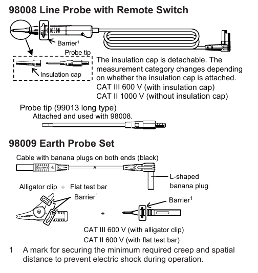
Line probe with remote switch 98008 1 connected to LINE terminal for line side measurement
Grounding probe group 98009 1 is connected to the EARTH terminal for measuring the grounding side
Shoulder strap 99018 1 hanging instrument, supports dual hand operation
Alkaline dry battery -4 instrument power supply (AA alkaline battery recommended)
User manual set IM MY600-01EN/92Z1/00C01C01-01Z2/PIM113-01Z2, each containing multilingual instructions and global contact information
2. Optional accessories (to be purchased separately)
According to the requirements of the measurement scenario, it is necessary to ensure that the accessories meet the rated parameters of the instrument:
Accessory Name Model/Part Number Usage
USB communication adapter 91030 is used to connect to a PC and transfer measurement data from memory
Hook probe tip 99012 replaces standard probe, suitable for special wiring scenarios
Long probe tip 99013 deep into narrow spaces for measurement, expanding measurement range
Safety regulations
1. Core safety warning (to avoid electric shock/equipment damage)
Laser and high voltage protection: When measuring insulation resistance, there is high voltage at the tip of the probe, and touching the probe or the tested circuit is prohibited; After measurement, wait for automatic discharge to complete(“ ⚠️” Symbol flashing+buzzing), then touch the circuit.
Measurement category restriction: The rated measurement category of the instrument is CAT III 600V, and it is prohibited to use it for CAT IV or main power circuits exceeding 600V; When the probe is paired with different accessories, the category is different (for example, 98008 with insulation cap is CAT III 600V, and without cap is CAT II 1000V).
Requirements for the tested equipment: Before measurement, the power supply of the DUT must be cut off, and the voltage measurement function must be used to confirm that there is no power before starting; Do not measure live circuits to avoid instrument damage or electric shock.
Equipment status check: If the instrument casing is damaged, the probe cable is exposed, or the battery compartment is damp, use is prohibited; After falling or colliding, it is necessary to contact the dealer for maintenance to avoid insulation protection failure.
2. Operation safety rules
Battery replacement: Before replacing, power off and remove the probe. It is forbidden to open the battery compartment during measurement; New batteries of the same type should be used to avoid mixing old and new/different models.
Environmental restrictions: Do not use in flammable gas, humid (with condensation) or outdoor rainy environments; Working temperature range -10~+50 ℃, storage temperature -20~+60 ℃, avoid direct sunlight.
Probe usage: Only Yokogawa designated probes can be used, damaged or aged probes should be replaced in a timely manner; Before connecting/disassembling the probe, it is necessary to disconnect it from the device being tested.
Core functions and operating procedures
1. Measurement mode and parameters
The instrument supports three core measurement modes, and the parameters and applicable scenarios for each mode are as follows:
(1) Voltage measurement (AC/DC automatic detection)
Range and Range: Automatic range (300.0V/600V), measurement range AC 2.0~600V (45~65Hz), DC ± 2.0~± 600V, over range display ">629V" (AC/positive DC) or "<-629V" (negative DC).
Accuracy: ± 1% reading ± 4 digits (23 ℃± 5 ℃, RH ≤ 80%), AC detected using true RMS, non sinusoidal (CF<2.5) requires an additional ± 1% error.
Operation steps:
Connect the line probe (98008) to the LINE terminal, and connect the ground probe (98009) to the EARTH terminal.
Set the range switch to "V/Ω" and connect the probes to the line side and ground side of the tested circuit.
No need to press the measurement switch, the instrument automatically detects AC/DC and displays the value (triggering a live warning when ≥ 30V:“ ⚠️” Blinking and buzzing.
(2) Insulation resistance measurement (core function)
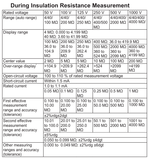
Rated voltage and range: Supports six rated voltages of 50V/100V/125V/250V/500V/1000V, with automatic range switching (such as 1000V range of 4~4000M Ω), and a fixed value displayed for exceeding the range (such as>4199M Ω).
Key parameters:
Open circuit voltage: 100-110% of rated voltage.
Short circuit current: ≤ 1.5mA (1000V range) to ensure measurement safety.
Accuracy: First effective range (such as 1000V range 0.100~1000M Ω) ± 2% reading ± 2 digits; Second effective range (1001~4000M Ω) ± 5% reading.
Featured Features:
Automatic discharge: After measurement, keep the probe connected, and the instrument will automatically release the charge of the measured capacitor load. Before the discharge is completed“ ⚠️” Flashing and buzzing.
Pass/Tail judgment: A reference value (0.001~4199M Ω) can be set. When the measured value is ≥ the reference value, the backlight flashes green and "PASS", otherwise it flashes red and "FAIL".
DAR/PI calculation: Automatically calculate the dielectric loss absorption ratio (DAR=1 minute value/15 second value) and polarization index (PI=10 minute value/1 minute value), ranging from 0.00 to 9.99, with ">9.99" displayed if out of range.
Operation steps:
Connect the probe, confirm that the tested device is powered off, and verify that there is no power using voltage measurement.
Turn the range switch to the corresponding rated voltage level (long press SELECT to switch between 125V/100V levels).
Connect the probe to the device under test, and simultaneously press the instrument's "measurement switch" and the probe's "remote switch" to start measuring (continuous measurement requires locking the measurement switch).
After the measurement is completed, wait for the automatic discharge to end before removing the probe.
(3) Low resistance measurement (on-off check)
Range and Range: Automatic Range (40.00 Ω/400.0 Ω/4000 Ω), Measurement Range 0.00-4199 Ω, Over Range Display ">4199 Ω".
Key parameters:
Open circuit voltage: DC 4~6.9V.
Measurement current: below 2 Ω ≥ 200mA, when the current is ≥ 200mA, a buzzer will sound to indicate on/off.
Accuracy: 0.20-4000 Ω± 2.5% reading ± 8 digits; 0~0.19 Ω± 8 digits (0 Ω calibration needs to be performed first).
Featured feature: 0 Ω calibration (can counteract probe and fuse resistance, up to 3 Ω), ensuring low resistance measurement accuracy.
Operation steps:
Turn the range switch to "V/Ω" and press SELECT to switch to low resistance mode.
Short circuit the probe, long press the "0 Ω ADJ" button to perform calibration (display "0.00 Ω" and light up the "0 Ω" indicator light).
Connect the probe to the tested circuit, press the measurement switch, and display the resistance value (beep when the current is ≥ 200mA).
2. Auxiliary functions
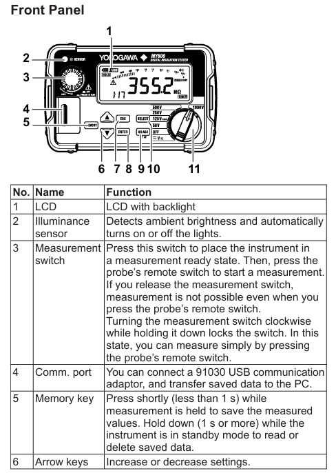
Backlight and LED lights: The illuminance sensor automatically detects the ambient brightness, automatically turns on the backlight and measurement point LED lights when dim, and automatically turns off after 2 minutes of inactivity; It can also be manually set to be normally off.
Automatic shutdown: Automatic shutdown after 10 minutes of inactivity (disabled during measurement or when the measurement switch is locked), with a warning beep before shutdown.
Clock settings: Year/month/day/hour/minute can be set, measurement data is automatically associated with timestamps, and there is a built-in lithium battery backup clock (with a lifespan of about 10 years).
Memory function: can store 1000 sets of measurement data (voltage/insulation resistance/low resistance), including DAR/PI, time, range and other information; Support data viewing and deletion (single/all), and transfer to PC through USB adapter.
System Settings and Data Management
1. Function configuration (long press SETUP to enter configuration mode)
Pass/Tail reference value: Set the judgment threshold for each voltage level, supporting preset values (such as default 0.5M Ω for 500V level) or custom values (0.001-4199M Ω).
Backlight/LED lights: Set to "ON" (automatic start stop) or "OFF" (normally off).
Buzzer: Set "ON" (live warning, discharge, on/off prompt) or "OFF" (turn off all beeps).
Clock calibration: Adjust the year/month/day/hour/minute to ensure accurate data timestamps.
2. Data management
Storage: When holding the measurement value, press the MemoRY button briefly to set the site number (SITE No.1/2, 0~99) and data number (automatically increasing) to complete the storage.
View: Press and hold the Memory button during standby time, select the data number using the directional keys, and view the measured values and station information.
Delete: When viewing data, select the number (or "ALL") and press ENTER to confirm the deletion (single or all).
Transmission: Connect to the PC via USB communication adapter (91030), install the driver, and export data using commands (refer to IM 91030-01EN manual).
Maintenance and repair
1. Daily maintenance
Battery management: When the battery level is low, the "battery icon" displays "empty" and needs to be replaced in a timely manner (4 AA alkaline batteries); Long term disuse requires removing the battery to avoid leaking and damaging the instrument.
Cleaning: Wipe the outer shell with a dry soft cloth, and do not use abrasives or solvents; The surface of the illuminance sensor needs to be kept clean to avoid affecting the automatic backlight/LED function.
Calibration cycle: It is recommended to calibrate once a year to ensure measurement accuracy. Calibration must be performed by Yokogawa certified personnel.
2. Fault handling and maintenance
Frequently Asked Questions:
Inaccurate measurement value: Check the battery level, probe connection, and perform 0 Ω calibration again for low resistance measurement.
Backlight/LED not on: Clean the illuminance sensor or manually confirm that the configuration mode is set to "ON".
Unable to store data: Memory is full (old data needs to be deleted), or the operation was not in the 'measurement value hold' state.
Maintenance restrictions: It is prohibited to disassemble the instrument by oneself (only battery replacement can open the battery compartment). For internal faults, please contact the Yokogawa dealer. Repairs involving safety insulation components require professional operation.
3. Disposal and Compliance
Equipment disposal: When disposing of equipment, local laws and regulations must be followed, and batteries (alkaline batteries and built-in lithium batteries) must be separated and classified for disposal.
Environmental Compliance: Compliant with EU RoHS Directive, WEEE Directive (prohibiting the mixing of household waste in EU regions), and EU Battery Directive (batteries must be recycled separately).
Product Specifications
Appearance dimensions: 156 (W) × 46 (H) × 97 (D) mm, weight approximately 490g (including battery).
Factory default settings: such as Pass/Tail reference values for each voltage level (0.5M Ω for 500V level), default "ON" for backlight/buzzer, default clearing of memory, etc.
- YOKOGAWA
- Reliance
- ADVANCED
- SEW
- ProSoft
- WATLOW
- Kongsberg
- FANUC
- VSD
- DCS
- PLC
- man-machine
- Covid-19
- Energy and Gender
- Energy Access
- Renewable Integration
- Energy Subsidies
- Energy and Water
- Net zero emission
- Energy Security
- Critical Minerals
- A-B
- petroleum
- Mine scale
- Sewage treatment
- cement
- architecture
- Industrial information
- New energy
- Automobile market
- electricity
- Construction site
- HIMA
- ABB
- Rockwell
- Schneider Modicon
- Siemens
- xYCOM
- Yaskawa
- Woodward
- BOSCH Rexroth
- MOOG
- General Electric
- American NI
- Rolls-Royce
- CTI
- Honeywell
- EMERSON
- MAN
- GE
- TRICONEX
- Control Wave
- ALSTOM
- AMAT
- STUDER
- KONGSBERG
- MOTOROLA
- DANAHER MOTION
- Bentley
- Galil
- EATON
- MOLEX
- Triconex
- DEIF
- B&W
- ZYGO
- Aerotech
- DANFOSS
- KOLLMORGEN
- Beijer
- Endress+Hauser
- schneider
- Foxboro
- KB
- REXROTH
- YAMAHA
- Johnson
- Westinghouse
- WAGO
- TOSHIBA
- TEKTRONIX
- BENDER
- BMCM
- SMC
- HITACHI
- HIRSCHMANN
- XP POWER
- Baldor
- Meggitt
- SHINKAWA
- Other Brands
- UniOP
- KUKA
- IBA
- Beckhoff
-
LTI SC52.0040.0012.0000.0 - Servo Drive
-
Lti SC52.0040.0012.0000.0 - Servo Drive
-
Milton Industries LTI Tool By Milton LT1240 - 1/2" Drive Lugnut Remover
-
LTi Drives SO84.200.P030.0000.0-W - Servo Spindle Drive
-
LTI DRIVES LSP08-035-320-30-B0R1PY170 - Servo Motor
-
LTI DRIVES SE84.200.SC00.0001.0-W - Servo Drive
-
Lust CDE34.005.W2.2 - Lti Drives Controller
-
LTi SO84.012.0030.0011.2 - ServoOne Servo Drive
-
LTi Drives SO CM-P.0010.11.00.0 - Servo Drive Controller
-
LTi CDE34.017.W3.0 - Servo Drive
-
LTI Drives CDB32.004, C2.0,SH - Positioning Controller
-
LUST CM-CAN1 - LTi DRIVES Communication Module
-
LTi SO84.012.1030.0000.2 - Servo Drive
-
LTI MOOG CDE54.044 - PITCHMASTER FREQUENCY CONVERTER 181-01019
-
MOOG LTI 181-01019 CDE54.044 - PITCHMASTER FREQUENCY CONVERTER
-
Lust LTi Drives CDE34.010,D2.0 - Servo Drive Controller
-
LTI SO84.032.0003.0101.2 - Servo Drive
-
Seagate 9CC132-302 Harris LTI-CS IRT-34-0021-01 - Hard Drive 160GB
-
LTI SO84.032.0003.0001.2 - Servo Drive
-
LTI SO24.007.0070.0000.1 - SERVO CONTROLLER
-
LTi drive CDA32.003.C3.0.H05-01.PC1 - Servo Drive
-
LTI SO84.016.0030.0000.2 - SERVO CONTROLLER
-
LUST LTI CD A34.008,W1.4, BR - SERVO DRIVE
-
MOOG LTI 181-01019 CDE54.044 - PITCHMASTER FREQUENCY CONVERTER
-
LTI MOOG 181-01019 - PITCH Master Servo Drive CDE54.044
-
LTI SERVO ONE SO84.045.0030.0001.2-W - Drive
-
LUST LTi SO84.032.0040.0000.2 - SERVO ONE DRIVE
-
LTi Drives LSH-074-2-30-3 20/T1,G6.1M - SERVO MOTOR
-
LTI SO84.016.0000.0101.2 - servo drive
-
LTI SA54.0550.0033.0000.0 - Servo Drive
-
LTI SA54.0550.0033.0000.0 - Servo Drive
-
LTI LT 4850 - 3/8" Drive 3-Pc Twist Socket Transmission Drain Plug Removal System
-
LTI Tools LT4400-30 Lock Technology - 3/4" Twist Socket 1/2" Drive Lugnut Remover
-
LTI Tools LT-1400C - 1/2 Drive Wheel Torque Extension Tool
-
LTI Tools LT1250 - 1/2" Drive Dual Sided Socket Lug Nut Remover Tool
-
LTI SO84.032.0003.0101.2 - Servo Drive
-
LTI MOOG 181-01019 - PITCH Master Servo Drive CDE54.044
-
MOOG LTI 181-01019 CDE54.044 - PITCHMASTER FREQUENCY CONVERTER
-
MOOG LTI 181-01019 CDE54.044 - PITCHMASTER FREQUENCY CONVERTER
-
MOOG LTI 181-01019 CDE54.044 - PITCHMASTER FREQUENCY CONVERTER
-
LTI SA54.0550.0033.0000.0 - Servo Drive
-
LTI Tools LT-4800 - 7 Piece Twist Socket 3/8" Drive Oil Drain Plug Removal Set
-
LTI SA54.0550.0033.0000.0 - Servo Drive
-
LTI Drive SO24.007.00300000.0 - Servo Drive
-
LTI TOOLS LTI 1400-I - Drive Wheel Torque Extension
-
LTI Tools LT4400-3 - 3/4" 19mm Twist Socket 1/2" Drive Lugnut
-
LTI TOOLS LTI 1400-BB - Drive Wheel Torque Extension
-
LTI SO84.032.0003.0101.2 - Servo Drive
-
LTI Tools LT-4512 - 3/8" Drive 12mm Twist Socket
-
LTI MOTION Luster SO84.032.0003.0001.2 - Servo Drive
-
LTI Tool By Milton LT1600P - 1" Drive Torx Stick
-
LTI Lust VF1424L,HF,OP2,S56 - Variable Frequency Drive
-
LUST CDA32.004,C1.4,H08,B0 - SERVO DFRIVE CM-CAN1 Module
-
LTI SO84.045.0002.0001.2-W - Drive
-
LTI Lust VF1404M,C9,PT1,BR1 - Inverter Type VF1404M
-
LTI SA54.0550.0033.0000.0 - Servo Drive
-
LTI Tools LT-1400C - 1/2" Drive Wheel Torque Extension
-
Lust LTI DRiVES CDA32.006, C3.0, H09 - Variateur De Fr茅quence Frequency Inverter
-
LTI MOOG CDE54.044 - PITCH master SERVO DRIVE
-
LTI MOOG CDE54.044 - PITCH master SERVO DRIVE
-
LTI SO84.143.0020.0101.2-W - servo drive
-
LTI MOTION SC34.0200.0011.0000.0 - Servo drives
-
LTI SO84.032.0003.0001.2 - Servo Drive
-
LTI DRIVES GmbH MS100 - Assembly Set Mounting Kit
-
LTI SO84.032.0003.0001.2 - Servo Drive
-
LTI SO84.032.0003.0001.2 - Servo Drive
-
LTI MOTION SO84.032.0003.0101.2 - servo drive
-
LTI SO84.032.0003.0101.2 - Servo Drive
-
LTI MOOG CDE54.044 - PITCH master SERVO DRIVE
-
LTI MOTION CDE32.004.C2.4 - Servo drives
-
LTI CDD34.032锛學x.x锛孊R锛孭C1 - Servo Drive
-
Lust LTI DRiVES CDA32.006, C3.0, H09 - Inversor De Frecuencia Frequency Inverter
-
Lust SO84.008.0030.1000.0 - Servo One LTi Drive
-
LTI MOTION SO84.032.0003.0101.2 - Servo drives
-
LUST LTi CDA32.004,C1.4 - SERVO DRIVE
-
LTI MOOG CDE54.044 - PITCH Master SERVO DRIVE
-
LTI KEBA CDB32.004 C2.7, SH - PN: 08673530 Frequency Inverter
-
LTI Tools LT-1400C - 1/2" Drive Wheel Torque Extension
-
LTI LT1400-E - 1/2" Drive Wheel Torque Extension
-
LTI MOOG 181-01019 - PITCH master SERVO DRIVE CDE54.044
-
LTI LSN-097-0510-30-560/T1 - Actuator Motor
-
LTI Tools LT 4800 - 7 Piece 3/8" Drive Twist Socket Oil Drain Plug Removal System
-
LTI DRIVES GmbH MS100 - MONTAGESET Assembly Set Mounting Kit
-
Lti SC52.0040.0012.0000.0 - Servo Drive
-
LTI DRIVES GmbH MS100 - Juego De Montaje Assembly Set Mounting Kit
-
LTi DSM4-14.2-21R83-200 - Drives servomoteur Servo Motor
-
MOOG CDE 54.044.GDA - Pitch Master Industrielle Turbine Lti Drive
-
LTI SO24.004.0030.1000.0 - Servo Drive Controller
-
Lti MOOG CDE54.044 - Pitch Master Servo Drive
-
Lust LTI DRiVES CDA32.006, C3.0, H09 - Inverter
-
LTI MOTION GMBH CDB34.006,W3.0,PC1,H39 - Frequency inverter
-
LTI SO84.032.0003.0001.2 - Servo Drive
-
MOOG CDE 54.044.D - Pitch Master Industrielle Turbine Lti Drive
-
LTI TOOLS LT-1460 - 1/2" DRIVE WHEEL TORQUE EXTENSION KIT 5 PIECE SET
-
Lust Cdb32.003, C2.4 - Lti Drives Servoregulador Frecuencia Servo Controller Inverter
-
Lust LTI DRIVES CDA32.006, C3.0, H09 - Frequency Inverter
-
Lust Lti SO82.004.0030.0000.2 - Servo Drive
-
LTI MOTION SC34.0200.0011.0000.0-SL - Servo drives
-
LTI MOTION SA54.0075.0033.0000.0 - Servo drives
-
LTI MOTION SC32.0075.1011.0000.0 - Servo drives
-
LTI Servo-One Junior SO22.006.0080.1000.0 - Servo Controller Servoregler
-
LUST CDA32.004, C1.4, H08, B0 - Servo Drive & LTI CM-CAN1 Module
-
LTI DRIVES LSP08-035-320-30-B0R1PY170 - Servo Motor
-
LUST LTI CDA32.004,C1.4.H08.B0 - SERVO CONTROLLER DRIVES
-
LUST LTi DRiVES CDS44.072LC1.2 - Servo Drive
-
Lti Servo-One Junior SO22.006.0082.1000.0 - Servo Controller Servoregler
-
LUST CDA32.008,C2.0,HF - Lti DRIVES Spindle Drive Inverter
-
LTI SO22.003.0082.0000.0 - Servo Drives One junior Servo Controller Servoregler
-
Lust Lti Drives CM-CAN1 - Communication Module
-
LUST Lti Drives Vf1202s, G8, I6 - Frequency Inverter Drive
-
LTI DRIVES BR-090.03.540.UR.H38 - Bremswiderstand Brake Resistor
-
LTi DRIVES PM-E40.2DRA054P - Wind Turbine Pitch Control Inverter
-
LTi Drives GmbH br-110.01.540-UR - Brake Resistor
-
LTI Drives LSN-097-0960-30-0560/T1,S4,B - Servo Motor
-
LUST CDA34.006.C2.0 - LTI Drives Servoregler
-
LUST LTI DRIVES SERVO ONE JUNIOR SO24.002.0020.0000.1 - Servo Drive Controller
-
LTI MOTION SO84.032.0003.0001.2 - Servo drives
-
LTI DDTD750V2-120 - IBOP ACTUATOR CYLINDER FOR TOP DRIVE
-
LTI CDE32.004, C2.4 - SERVO DRIVE
-
LUST LTI DRIVES CDD34.017 W3.4PC1 - Servo Drive Controller
-
LTI CDA3208,C3,0,HF - AC SERVO DRIVE
-
LUST LTI DRIVES LSH-074-3-30-560/T1,G6.1S - SERVO MOTOR
-
LUST Lti CDB32.004.C2.4.SH - AC Servo Drive
-
LTi CDA32.006, C3.0, H09 - Servo Drive
-
LTI SO22.003.0010.0000.0 - Servo Drive Servo one junior Servoregler Controller
-
LTi Drives DSM4-14.2-21R83-200 - Servo Motor
-
LUST Lti Drives Lsh-097-1-30-560/T1, 1R - Servomotor
-
LTI 1237 - 7 Piece 1/2" Drive Flip Socket Set

K-JIANG

Add: Jimei North Road, Jimei District, Xiamen, Fujian, China
Tell:+86-15305925923