
K-WANG


YOKOGAWA AQ7290 Series Optical Time Domain Reflectometer OTDR
YOKOGAWA AQ7290 Series Optical Time Domain Reflectometer OTDR
Product basic information
1. Product positioning and core applications
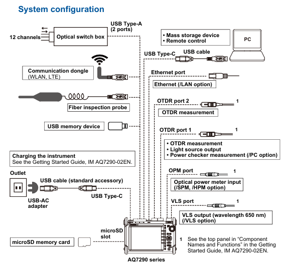
The AQ7290 series OTDR is a professional equipment used for fiber link detection. Its core function is to analyze the transmission loss, joint loss, fault location (such as breakage, bending) and other parameters of the fiber by emitting optical pulses and receiving reflected light. It is mainly used for:
Access network: Fiber optic installation and maintenance between telecommunications operators and users (mainly single-mode fiber optic).
Enterprise network: Fiber optic detection of internal communication networks within enterprises or buildings.
Long distance network: troubleshooting and performance monitoring of backbone fiber optic links between telecommunications operators.
2. Manual system and version information
Supporting documents: including Chinese specific documents (IM 739883-92Z1), European language safety manual (IM 00C01C01-01Z1), global contact list (PIM 113-01Z2), and communication interface manual (IM AQ7290-17EN) stored in device memory, which needs to be downloaded to PC for viewing.
Language code: In the manual number, "EN" represents English, "Z1" represents Chinese and other languages. Users can access it through the Yokogawa Customer Portal( https://myportal.yokogawa.com/ )Obtain the corresponding version.
Version iteration: The current version is the first edition in April 2025, and the content may change without prior notice due to product feature upgrades. The latest version should refer to the official website.
Trademark Statement: Mentioning brand trademarks such as Microsoft, Apple, Google, etc., omitted in the manual ® The TM symbol and other brand names belong to their respective holders.
Core functions and operating procedures
1. Basic measurement function (OTDR core)
(1) Optical pulse measurement mode
Support two core measurement modes to meet different scenario requirements:
Measurement mode, functional characteristics, applicable scenarios
Average measurement (TRACE/MAP mode): Take the average of multiple measurements to reduce noise interference; Automatically analyze events after measurement, and switch between "TRACE" or "MAP" to accurately detect weak events (such as low loss connectors) and generate formal detection reports
Real time measurement (only available in TRACE mode) updates waveforms in real-time, supports dynamic adjustment of parameters such as wavelength and distance range, real-time monitoring during fiber installation, and quick troubleshooting of obvious faults
(2) Key measurement parameter settings
Wavelength: Different models support 1310nm, 1550nm, 1625nm, 1650nm, etc. For example, AQ7293F supports 1310/1550/1650nm, and AQ7293H supports 1310/1550/1625nm.
Distance range: Supports AUTO (automatic matching of fiber length) and manual setting of 100m-512km. It is necessary to select a range greater than the actual length of the fiber to ensure complete measurement.
Pulse width: Short pulses (3ns-30ns) are suitable for close range high-resolution measurement, while long pulses (1 μ s-20 μ s) are suitable for long-distance measurement, and can be manually set or automatically matched with a distance range.
Average frequency/duration: The average frequency supports 2 ¹⁰ -2 ² ⁰ times, with a duration of 5-30 minutes. The larger the frequency/duration, the higher the measurement accuracy but the longer the time consumption.
(3) Event analysis function
Automatically detect "events" (such as joints, fractures, bends) in fiber optic links and calculate key parameters:
Event types: including joint loss, reflection loss, bending loss, splitter loss, fiber optic endpoint (Fresnel reflection), etc., visually displayed in MAP mode through icons (such as "⊡" for joints and "■" for endpoints).
Analysis parameters: The joint loss threshold (0.01-9.99dB), reflection loss threshold (20-70dB), and fiber endpoint threshold (3-65dB) can be set. Events exceeding the threshold will be marked as "fault".
Manual adjustment: supports inserting/deleting events, editing event marker positions, and solving noise misjudgment or weak event missed detection problems.
2. Utility function
The device supports parallel use of multiple tools and can synchronously perform other detections during OTDR measurement, improving work efficiency:
Key parameters/options for the core purpose of tool functionality
Light Source fiber loss measurement, fiber identification output wavelength consistent with OTDR (such as 1310/1550nm), supports continuous light (CW) or modulated light (270Hz/1kHz/2kHz)
Visible light source (/VLS option) visually locates fiber breakpoints, checks multi-core fiber core sequence, fixed wavelength 650nm, supports CW or 2Hz modulation light
Optical power meter (/SPM//HPM option) measures optical signal power, fiber loss/SPM (standard): 800-1700nm,/HPM (high power): maximum+27dBm, supports logging (CSV format)
Power checker (/PC option) detects the presence of communication light in the fiber (to avoid interference) and measures wavelengths of 1310/1490/1550/1625/1650nm
Fiber end face detection probe (/FST option) can detect stains and scratches on the fiber end face. It supports USB or wireless connection and can determine the size of the fiber core/cladding/contact area (in accordance with IEC 61300-3-35 standard)
3. Advanced Application Features
Provide specialized solutions for complex scenarios, covering requirements such as multi-core fiber optics and long-term monitoring
(1) OTDR Smart Mapper
Function: Take multiple average measurements of the same wavelength using different pulse widths, automatically concatenate waveforms (narrow pulses for resolution at close range and wide pulses for coverage at far range), and generate link event maps.
Advantages: No need to manually switch pulse width, more accurate event localization for complex links (including spectrometers), and beginners can quickly understand the link structure.
(2) Multi Fiber Project
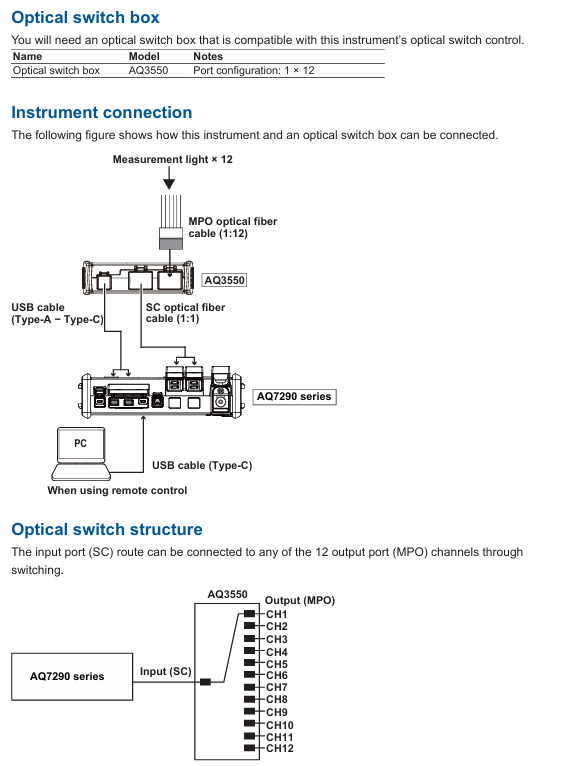
Project management: Package the measurement conditions (wavelength, distance range), number of cores (1-2000 cores), and core sequence (such as numbered 1a-1d) of multi-core optical fibers into a "project", supporting batch measurement and unified data management.
Batch operation: The screen displays the chip numbers in a table, and the measurement status is marked with colors (gray=stored data, green=qualified, red=unqualified) to quickly skip chip numbers that do not need to be measured and avoid omissions.
(3) Fiber optic monitoring (Schedule Measurement,/MNT option)
Timed measurement: Automatically perform OTDR measurement at set intervals (1-60min) and durations (1-120 days) to monitor changes in fiber loss (such as aging and external damage).
Data storage: Measurement data is automatically classified and stored by timestamp (SOR format waveform, CSV format log), supporting post analysis of fault occurrence time.
(4) Auto Loss Test/Multi Fiber Loss Test
Single core testing: Two devices work together, one as a light source and the other as an optical power meter, automatically switching wavelengths (1310/1550nm) to measure fiber loss.
Multi core testing: Synchronize multi-core fiber loss testing through the "master-slave mode", where the master device sends project configurations and the slave device performs measurements. The results are automatically transmitted back to the master device, making it suitable for batch acceptance of multi-core links.
(5) Advanced Analysis
Multi waveform comparison: Load up to 4 waveforms, support vertical offset adjustment, visually compare the loss differences of different time periods/links.
Bidirectional trajectory analysis: Combine waveforms measured from both ends of the fiber to accurately calculate the joint loss of fibers with different backscattering coefficients.
Differential trajectory analysis: Display the difference between two waveforms to quickly locate newly added loss points (such as fiber damage caused by later construction).
Data Management and Report Generation
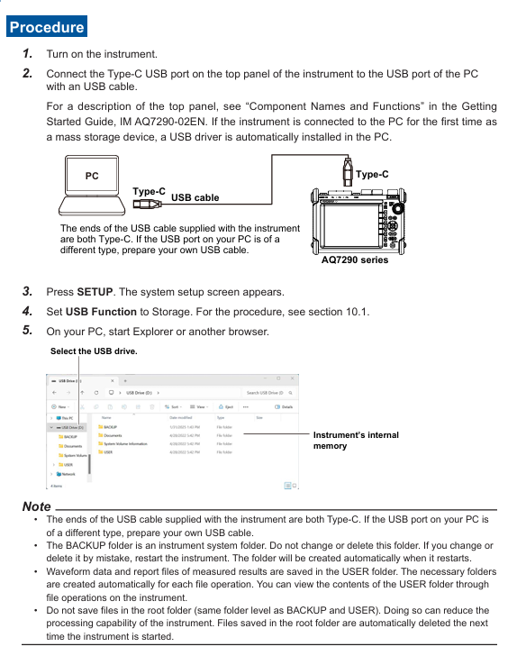
1. Data storage and loading
Supporting media: Internal memory (approximately 1GB), USB storage device (USB 1.0/1.1/2.0), microSD card (SDC/SDHC/SDXC), up to 2 USB devices can be connected simultaneously.
File format:
SOR: Complies with Telcordia SR-4731 standard, stores waveform data and measurement conditions, and can be used for post analysis or imported into PC simulation software.
SET: Only stores measurement/analysis conditions for rapid reproduction of the same testing environment.
PDF: Generate reports for waveforms, event lists, and measurement conditions, supporting custom inclusion items such as company name and fiber optic identification.
CSV: Stores event data or optical power logs for easy secondary analysis using tools such as Excel.
BMP/JPG: Screenshots used to record on-site inspection results.
Auto Save: After the average measurement is completed, the data can be automatically saved, supporting storage by date or custom path classification to avoid data loss.
2. Report generation
Real time report: After the measurement is completed, the current waveform and event analysis results can be generated into PDF reports, including link maps, event lists, measurement conditions, and other information.
Batch report: Select multiple SOR files to automatically generate multi page PDF reports, support sorting by file name/date/ID, suitable for batch project acceptance.
Custom settings: tags such as company name, fiber ID, and tester can be added, and the report format supports comparing 1 waveform per page or 2 waveforms per page.
System settings and remote control
1. Basic system settings
Display settings: Supports screen themes (dark/light), brightness adjustment (4 levels, including OFF), wavelength/distance units (km/m), and decimal places (1-3).
Power management: In battery mode, automatic sleep mode can be set (1/5/10/30min no operation), LCD backlight can be turned off to extend battery life; The USB-AC adapter can maintain high brightness when powered.
Language and Shortcut Keys: Supports multiple languages (based on device suffix code), and can assign commonly used functions (such as saving and report generation) to the UTIL key for one click calling.
2. Network and Remote Control
Wired network (/LAN option): Supports 10BASE-T/100BASE-TX Ethernet, realizes PC remote control through TCP/IP protocol, and can transmit measurement data to the server.
Wireless network: Connect to a wireless LAN adapter (recommended model required), supporting access point mode (device as hotspot) or site mode (connected to existing WiFi), suitable for remote operation in Ethernet free scenarios.
LTE Dongle: Inserting an LTE adapter can connect remote devices through mobile networks, suitable for outdoor environments without WiFi/Ethernet.
Web server: PC browser input device IP address, can be accessed through "control mode" (remote device operation) or "view mode" (only view screen and download files), without the need to install dedicated software.
Safety and Maintenance
1. Safety regulations
Laser safety: When the equipment emits high-power laser (OTDR port, VLS port), it is forbidden to directly look at the port or disconnect the fiber during operation. If the fiber is not connected, the port cover should be covered to avoid eye damage.
Wiring safety: Before measurement, confirm that the fiber optic connection is correct (voltage line connected to voltage terminal, current line connected to current terminal). Do not touch the terminals during high voltage/high current output, and regularly check whether the terminals are overheated or loose.
Fault handling: If there is smoke, odor, or abnormal noise, immediately cut off the power and disconnect the load; When the output is automatically turned off (such as overload protection), troubleshoot and then turn it back on.
2. Maintenance and repair
Filter cleaning: Check and clean the rear air inlet filter every 3 months. If it is dirty, clean it with neutral detergent and let it dry naturally. Blockage can cause the equipment to overheat; The filter screen is damaged and needs to be replaced by contacting a Yokogawa dealer.
Self check function: Automatically perform self check (check fan, voltage/current range, internal circuit) when turned on, or manually trigger. If the self check fails, an error code will be displayed (such as E.901 indicating fan fault).
Calibration and replacement: It is recommended to calibrate once a year to ensure accuracy. Cooling fans (3 years), filters (1 year), and LCDs (approximately 40000 hours) should be replaced according to the recommended cycle, and maintenance should be carried out by Yokogawa certified personnel.
Storage conditions: When not in use for a long time, it should be stored in an environment with a temperature of -20~60 ℃ and a humidity of 10%~90% (no condensation), avoiding direct sunlight, vibration, or corrosive gases.
- YOKOGAWA
- Reliance
- ADVANCED
- SEW
- ProSoft
- WATLOW
- Kongsberg
- FANUC
- VSD
- DCS
- PLC
- man-machine
- Covid-19
- Energy and Gender
- Energy Access
- Renewable Integration
- Energy Subsidies
- Energy and Water
- Net zero emission
- Energy Security
- Critical Minerals
- A-B
- petroleum
- Mine scale
- Sewage treatment
- cement
- architecture
- Industrial information
- New energy
- Automobile market
- electricity
- Construction site
- HIMA
- ABB
- Rockwell
- Schneider Modicon
- Siemens
- xYCOM
- Yaskawa
- Woodward
- BOSCH Rexroth
- MOOG
- General Electric
- American NI
- Rolls-Royce
- CTI
- Honeywell
- EMERSON
- MAN
- GE
- TRICONEX
- Control Wave
- ALSTOM
- AMAT
- STUDER
- KONGSBERG
- MOTOROLA
- DANAHER MOTION
- Bentley
- Galil
- EATON
- MOLEX
- Triconex
- DEIF
- B&W
- ZYGO
- Aerotech
- DANFOSS
- KOLLMORGEN
- Beijer
- Endress+Hauser
- schneider
- Foxboro
- KB
- REXROTH
- YAMAHA
- Johnson
- Westinghouse
- WAGO
- TOSHIBA
- TEKTRONIX
- BENDER
- BMCM
- SMC
- HITACHI
- HIRSCHMANN
- XP POWER
- Baldor
- Meggitt
- SHINKAWA
- Other Brands
- UniOP
- KUKA
- IBA
- Beckhoff
-
LTI SC52.0040.0012.0000.0 - Servo Drive
-
Lti SC52.0040.0012.0000.0 - Servo Drive
-
Milton Industries LTI Tool By Milton LT1240 - 1/2" Drive Lugnut Remover
-
LTi Drives SO84.200.P030.0000.0-W - Servo Spindle Drive
-
LTI DRIVES LSP08-035-320-30-B0R1PY170 - Servo Motor
-
LTI DRIVES SE84.200.SC00.0001.0-W - Servo Drive
-
Lust CDE34.005.W2.2 - Lti Drives Controller
-
LTi SO84.012.0030.0011.2 - ServoOne Servo Drive
-
LTi Drives SO CM-P.0010.11.00.0 - Servo Drive Controller
-
LTi CDE34.017.W3.0 - Servo Drive
-
LTI Drives CDB32.004, C2.0,SH - Positioning Controller
-
LUST CM-CAN1 - LTi DRIVES Communication Module
-
LTi SO84.012.1030.0000.2 - Servo Drive
-
LTI MOOG CDE54.044 - PITCHMASTER FREQUENCY CONVERTER 181-01019
-
MOOG LTI 181-01019 CDE54.044 - PITCHMASTER FREQUENCY CONVERTER
-
Lust LTi Drives CDE34.010,D2.0 - Servo Drive Controller
-
LTI SO84.032.0003.0101.2 - Servo Drive
-
Seagate 9CC132-302 Harris LTI-CS IRT-34-0021-01 - Hard Drive 160GB
-
LTI SO84.032.0003.0001.2 - Servo Drive
-
LTI SO24.007.0070.0000.1 - SERVO CONTROLLER
-
LTi drive CDA32.003.C3.0.H05-01.PC1 - Servo Drive
-
LTI SO84.016.0030.0000.2 - SERVO CONTROLLER
-
LUST LTI CD A34.008,W1.4, BR - SERVO DRIVE
-
MOOG LTI 181-01019 CDE54.044 - PITCHMASTER FREQUENCY CONVERTER
-
LTI MOOG 181-01019 - PITCH Master Servo Drive CDE54.044
-
LTI SERVO ONE SO84.045.0030.0001.2-W - Drive
-
LUST LTi SO84.032.0040.0000.2 - SERVO ONE DRIVE
-
LTi Drives LSH-074-2-30-3 20/T1,G6.1M - SERVO MOTOR
-
LTI SO84.016.0000.0101.2 - servo drive
-
LTI SA54.0550.0033.0000.0 - Servo Drive
-
LTI SA54.0550.0033.0000.0 - Servo Drive
-
LTI LT 4850 - 3/8" Drive 3-Pc Twist Socket Transmission Drain Plug Removal System
-
LTI Tools LT4400-30 Lock Technology - 3/4" Twist Socket 1/2" Drive Lugnut Remover
-
LTI Tools LT-1400C - 1/2 Drive Wheel Torque Extension Tool
-
LTI Tools LT1250 - 1/2" Drive Dual Sided Socket Lug Nut Remover Tool
-
LTI SO84.032.0003.0101.2 - Servo Drive
-
LTI MOOG 181-01019 - PITCH Master Servo Drive CDE54.044
-
MOOG LTI 181-01019 CDE54.044 - PITCHMASTER FREQUENCY CONVERTER
-
MOOG LTI 181-01019 CDE54.044 - PITCHMASTER FREQUENCY CONVERTER
-
MOOG LTI 181-01019 CDE54.044 - PITCHMASTER FREQUENCY CONVERTER
-
LTI SA54.0550.0033.0000.0 - Servo Drive
-
LTI Tools LT-4800 - 7 Piece Twist Socket 3/8" Drive Oil Drain Plug Removal Set
-
LTI SA54.0550.0033.0000.0 - Servo Drive
-
LTI Drive SO24.007.00300000.0 - Servo Drive
-
LTI TOOLS LTI 1400-I - Drive Wheel Torque Extension
-
LTI Tools LT4400-3 - 3/4" 19mm Twist Socket 1/2" Drive Lugnut
-
LTI TOOLS LTI 1400-BB - Drive Wheel Torque Extension
-
LTI SO84.032.0003.0101.2 - Servo Drive
-
LTI Tools LT-4512 - 3/8" Drive 12mm Twist Socket
-
LTI MOTION Luster SO84.032.0003.0001.2 - Servo Drive
-
LTI Tool By Milton LT1600P - 1" Drive Torx Stick
-
LTI Lust VF1424L,HF,OP2,S56 - Variable Frequency Drive
-
LUST CDA32.004,C1.4,H08,B0 - SERVO DFRIVE CM-CAN1 Module
-
LTI SO84.045.0002.0001.2-W - Drive
-
LTI Lust VF1404M,C9,PT1,BR1 - Inverter Type VF1404M
-
LTI SA54.0550.0033.0000.0 - Servo Drive
-
LTI Tools LT-1400C - 1/2" Drive Wheel Torque Extension
-
Lust LTI DRiVES CDA32.006, C3.0, H09 - Variateur De Fr茅quence Frequency Inverter
-
LTI MOOG CDE54.044 - PITCH master SERVO DRIVE
-
LTI MOOG CDE54.044 - PITCH master SERVO DRIVE
-
LTI SO84.143.0020.0101.2-W - servo drive
-
LTI MOTION SC34.0200.0011.0000.0 - Servo drives
-
LTI SO84.032.0003.0001.2 - Servo Drive
-
LTI DRIVES GmbH MS100 - Assembly Set Mounting Kit
-
LTI SO84.032.0003.0001.2 - Servo Drive
-
LTI SO84.032.0003.0001.2 - Servo Drive
-
LTI MOTION SO84.032.0003.0101.2 - servo drive
-
LTI SO84.032.0003.0101.2 - Servo Drive
-
LTI MOOG CDE54.044 - PITCH master SERVO DRIVE
-
LTI MOTION CDE32.004.C2.4 - Servo drives
-
LTI CDD34.032锛學x.x锛孊R锛孭C1 - Servo Drive
-
Lust LTI DRiVES CDA32.006, C3.0, H09 - Inversor De Frecuencia Frequency Inverter
-
Lust SO84.008.0030.1000.0 - Servo One LTi Drive
-
LTI MOTION SO84.032.0003.0101.2 - Servo drives
-
LUST LTi CDA32.004,C1.4 - SERVO DRIVE
-
LTI MOOG CDE54.044 - PITCH Master SERVO DRIVE
-
LTI KEBA CDB32.004 C2.7, SH - PN: 08673530 Frequency Inverter
-
LTI Tools LT-1400C - 1/2" Drive Wheel Torque Extension
-
LTI LT1400-E - 1/2" Drive Wheel Torque Extension
-
LTI MOOG 181-01019 - PITCH master SERVO DRIVE CDE54.044
-
LTI LSN-097-0510-30-560/T1 - Actuator Motor
-
LTI Tools LT 4800 - 7 Piece 3/8" Drive Twist Socket Oil Drain Plug Removal System
-
LTI DRIVES GmbH MS100 - MONTAGESET Assembly Set Mounting Kit
-
Lti SC52.0040.0012.0000.0 - Servo Drive
-
LTI DRIVES GmbH MS100 - Juego De Montaje Assembly Set Mounting Kit
-
LTi DSM4-14.2-21R83-200 - Drives servomoteur Servo Motor
-
MOOG CDE 54.044.GDA - Pitch Master Industrielle Turbine Lti Drive
-
LTI SO24.004.0030.1000.0 - Servo Drive Controller
-
Lti MOOG CDE54.044 - Pitch Master Servo Drive
-
Lust LTI DRiVES CDA32.006, C3.0, H09 - Inverter
-
LTI MOTION GMBH CDB34.006,W3.0,PC1,H39 - Frequency inverter
-
LTI SO84.032.0003.0001.2 - Servo Drive
-
MOOG CDE 54.044.D - Pitch Master Industrielle Turbine Lti Drive
-
LTI TOOLS LT-1460 - 1/2" DRIVE WHEEL TORQUE EXTENSION KIT 5 PIECE SET
-
Lust Cdb32.003, C2.4 - Lti Drives Servoregulador Frecuencia Servo Controller Inverter
-
Lust LTI DRIVES CDA32.006, C3.0, H09 - Frequency Inverter
-
Lust Lti SO82.004.0030.0000.2 - Servo Drive
-
LTI MOTION SC34.0200.0011.0000.0-SL - Servo drives
-
LTI MOTION SA54.0075.0033.0000.0 - Servo drives
-
LTI MOTION SC32.0075.1011.0000.0 - Servo drives
-
LTI Servo-One Junior SO22.006.0080.1000.0 - Servo Controller Servoregler
-
LUST CDA32.004, C1.4, H08, B0 - Servo Drive & LTI CM-CAN1 Module
-
LTI DRIVES LSP08-035-320-30-B0R1PY170 - Servo Motor
-
LUST LTI CDA32.004,C1.4.H08.B0 - SERVO CONTROLLER DRIVES
-
LUST LTi DRiVES CDS44.072LC1.2 - Servo Drive
-
Lti Servo-One Junior SO22.006.0082.1000.0 - Servo Controller Servoregler
-
LUST CDA32.008,C2.0,HF - Lti DRIVES Spindle Drive Inverter
-
LTI SO22.003.0082.0000.0 - Servo Drives One junior Servo Controller Servoregler
-
Lust Lti Drives CM-CAN1 - Communication Module
-
LUST Lti Drives Vf1202s, G8, I6 - Frequency Inverter Drive
-
LTI DRIVES BR-090.03.540.UR.H38 - Bremswiderstand Brake Resistor
-
LTi DRIVES PM-E40.2DRA054P - Wind Turbine Pitch Control Inverter
-
LTi Drives GmbH br-110.01.540-UR - Brake Resistor
-
LTI Drives LSN-097-0960-30-0560/T1,S4,B - Servo Motor
-
LUST CDA34.006.C2.0 - LTI Drives Servoregler
-
LUST LTI DRIVES SERVO ONE JUNIOR SO24.002.0020.0000.1 - Servo Drive Controller
-
LTI MOTION SO84.032.0003.0001.2 - Servo drives
-
LTI DDTD750V2-120 - IBOP ACTUATOR CYLINDER FOR TOP DRIVE
-
LTI CDE32.004, C2.4 - SERVO DRIVE
-
LUST LTI DRIVES CDD34.017 W3.4PC1 - Servo Drive Controller
-
LTI CDA3208,C3,0,HF - AC SERVO DRIVE
-
LUST LTI DRIVES LSH-074-3-30-560/T1,G6.1S - SERVO MOTOR
-
LUST Lti CDB32.004.C2.4.SH - AC Servo Drive
-
LTi CDA32.006, C3.0, H09 - Servo Drive
-
LTI SO22.003.0010.0000.0 - Servo Drive Servo one junior Servoregler Controller
-
LTi Drives DSM4-14.2-21R83-200 - Servo Motor
-
LUST Lti Drives Lsh-097-1-30-560/T1, 1R - Servomotor
-
LTI 1237 - 7 Piece 1/2" Drive Flip Socket Set

K-JIANG

Add: Jimei North Road, Jimei District, Xiamen, Fujian, China
Tell:+86-15305925923