
K-WANG


Honeywell Midas-M Multi Gas Transmitter
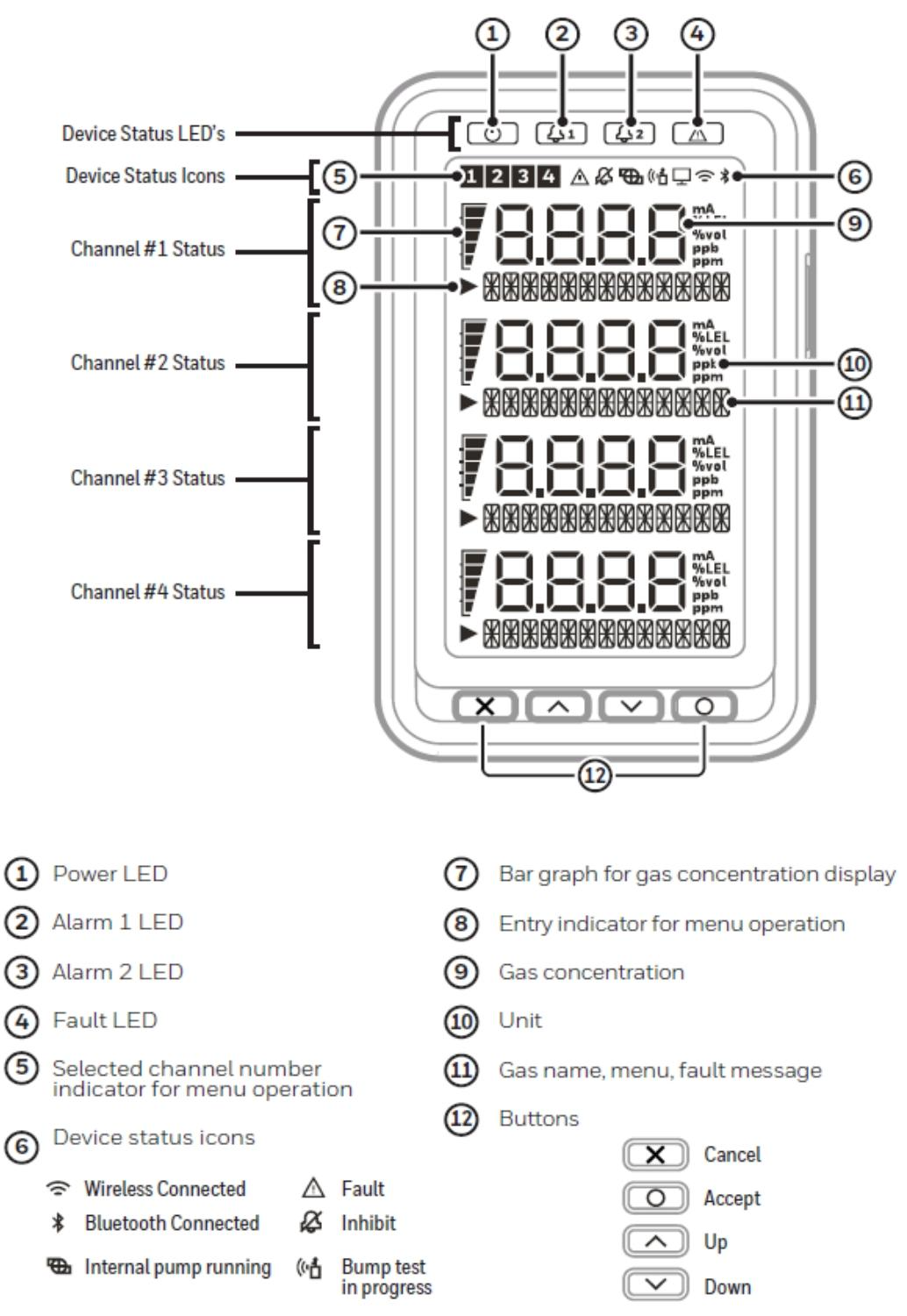
The overall architecture of the equipment consists of four core components: the main module, installation bracket assembly, sensor box, and pump module. This modular design not only facilitates installation and maintenance, but also allows for flexible configuration according to different detection requirements. The user interface includes a backlit LCD display screen, LED indicator lights, and a four key operation keyboard, which can intuitively display information such as gas concentration and alarm status, and support parameter settings and functional operations.
In terms of communication and power supply, Midas-M has high flexibility, supporting 3 onboard relays, 0-21mA analog output, Modbus/TCP digital communication, and Power over Ethernet (PoE). It can achieve the integration of power, control, and data transmission through a single Ethernet connection, greatly simplifying system wiring.
Honeywell Midas-M Multi Gas Transmitter
Product core positioning and design architecture
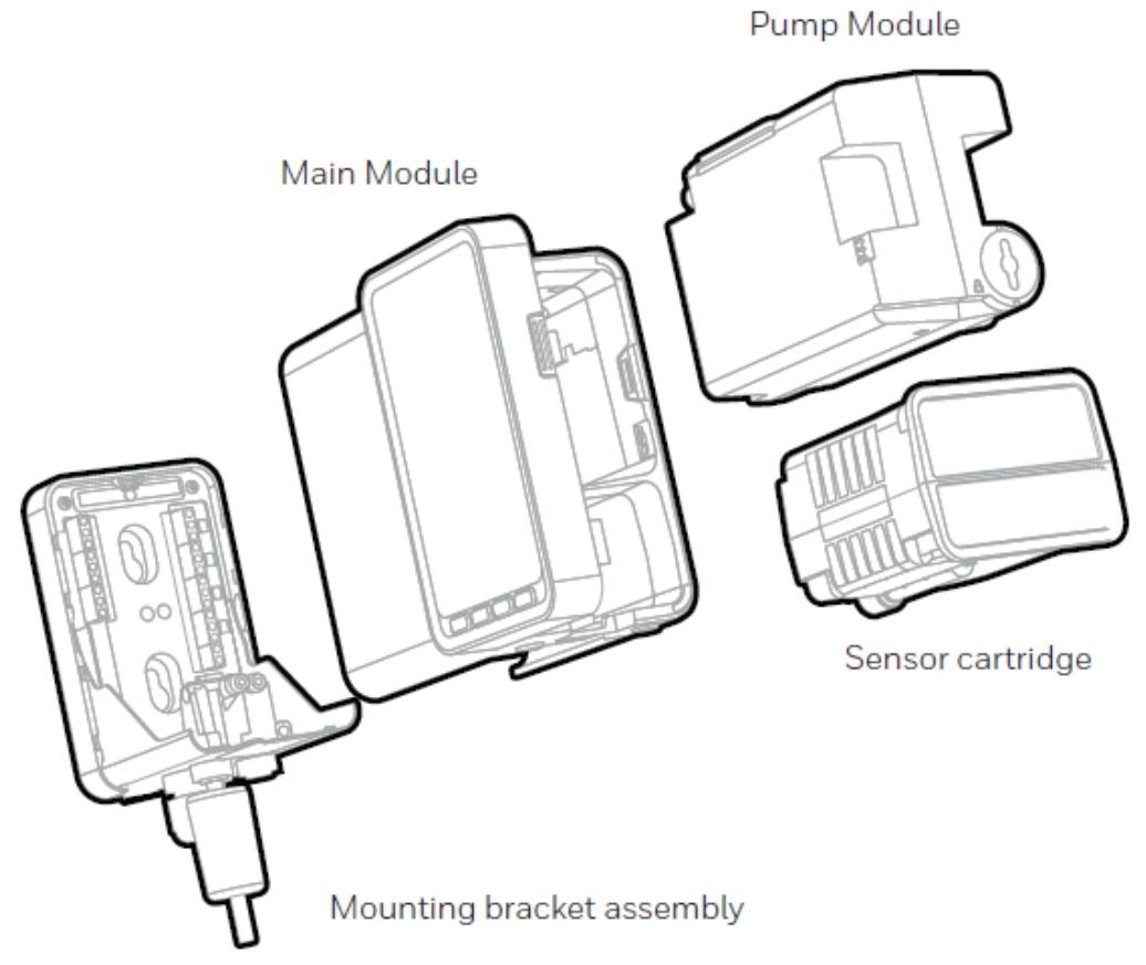
As a fixed single point extraction multi gas transmitter, Honeywell Midas-M adopts an innovative 4-in-1 multi gas detection design. Its core function is to extract gas samples from local or remote sampling points to the sensor box inside the chassis for analysis. Its design goal is to meet the detection requirements of toxic, flammable gases and oxygen in the semiconductor and other manufacturing industries, suitable for non explosive environments in indoor safe areas.
The overall architecture of the equipment consists of four core components: the main module, installation bracket assembly, sensor box, and pump module. This modular design not only facilitates installation and maintenance, but also allows for flexible configuration according to different detection requirements. The user interface includes a backlit LCD display screen, LED indicator lights, and a four key operation keyboard, which can intuitively display information such as gas concentration and alarm status, and support parameter settings and functional operations.
In terms of communication and power supply, Midas-M has high flexibility, supporting 3 onboard relays, 0-21mA analog output, Modbus/TCP digital communication, and Power over Ethernet (PoE). It can achieve the integration of power, control, and data transmission through a single Ethernet connection, greatly simplifying system wiring.
Installation process and technical specifications
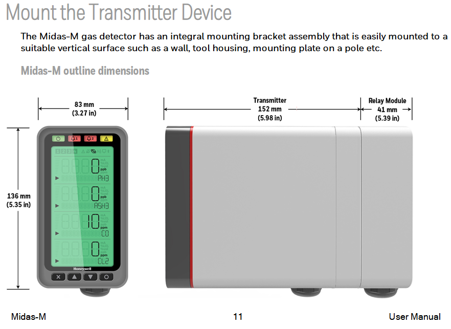
(1) Mechanical installation details
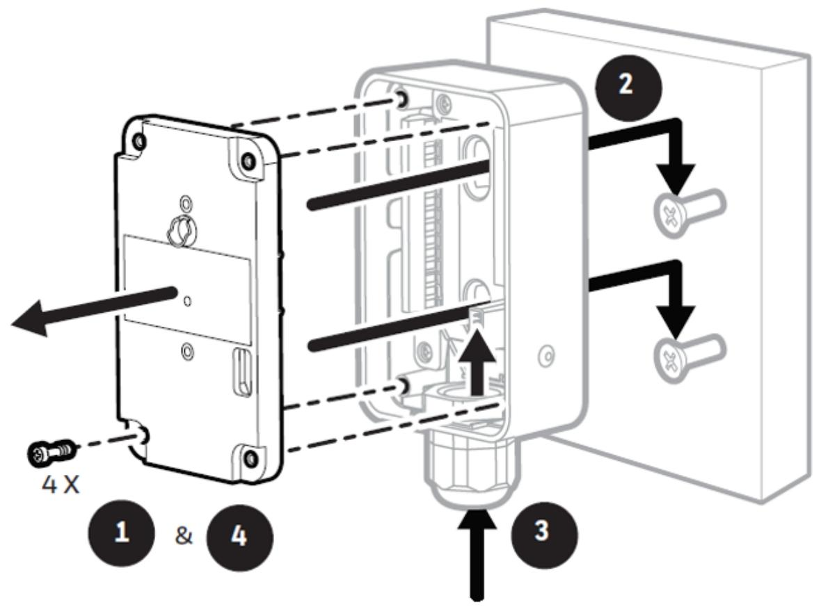
Transmitter installation: Adopting a step-by-step installation strategy, first fix the installation bracket, and then install the main module. The specific steps are: remove the equipment door → loosen the fixing screws → pull out the main module → drill holes according to the template (hole spacing 55.9mm) → fix the bracket with M4 screws → align the main module with the bracket's rounded corner positioning → horizontally push in the main module to fully connect the connector and pipeline → tighten the bottom fixing screws. Special attention should be paid to removing the internal packaging card of the fixed pump, otherwise it may cause equipment damage.
Relay module installation: independent of the main module installation, the steps include: removing 4 screws and cover plate → positioning the module on the pre installed screws and tightening it → threading and connecting to the terminal block → resetting the cover plate and screws → docking the module connector → fixing the bracket and module with special screws.
(2) Fluid system configuration
Sampling and exhaust pipeline parameters:
Inlet sampling: the maximum length is 30m (100ft), the vacuum degree at the sampling point is ≤ -25.4cm H ₂ O. It is recommended to use a 1/8-inch ID thick wall Teflon FEP tube, the flow is stable at 600cc/min, and different pipe diameters correspond to different transmission times (25 seconds for 1/8-inch ID, 53 seconds for 3/16 inch ID).
Export exhaust: maximum length 30m (100ft), back pressure ≤ 20.3cm H ₂ O, pipeline specification 4.76mm ID × 6.35mm OD.
Pipeline preparation and filtration: The pipeline needs to be vertically cut and deburred, and the depth of insertion into the equipment port should be 15.5mm (marked for confirmation). External filters must be used: 780248 for ordinary gases and 1830-0055 or 1991-0147 for corrosive gases. It is recommended to replace them every 3 months.
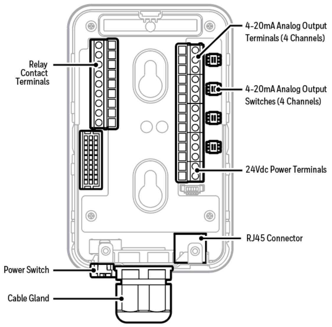
(3) Electrical Connection Specification
Power requirements: Supports 24VDC discrete power supply or 48VDC PoE power supply (IEEE 802.3af standard), both cannot be connected simultaneously. Maximum power consumption: Under normal operating conditions, it is about 5W, and at full load (4-channel alarm+maximum pipeline load), it is ≤ 11.45W.
Terminal definition and wiring: The terminal supports 24-14 AWG wires (recommended 16 AWG), including interfaces for power supply, 4-20mA output, relays, etc. Among them, the 4-20mA output can be configured as a 3-wire source type, 3-wire drain type, or 4-wire isolation type. When wiring, attention should be paid to the switch settings (INT/NEXT).
Grounding requirements: If the metal casing of the equipment is not directly connected to the grounded metal surface, a dedicated grounding terminal must be connected to the external grounding electrode through PG16 glass; When using PoE, shielded CAT5 cables should be used to avoid interference from grounding loops.
(4) Installation of sensor box
The sensor box supports plug and play, and it is necessary to confirm that the model matches the detected gas before installation. The steps are: power off → open the door → remove the BiAS battery module and plug cap → align the sensor box pins and slots → gently push until fully engaged → close the door → press the "O" key to clear the "Detect New Cartridge" prompt → confirm that the green light is flashing, the yellow/red light is off, and the displayed concentration is zero.
Operational functions and system configuration
(1) Core working mode
Monitoring mode: The default operating mode of the device displays real-time gas concentration (with units and bar charts), channel status, and system icons (pump running, wireless connection, etc.). The output performance under different states is as follows:
Alarm 1: Relay 1 is activated, 4-20mA varies with concentration, corresponding to a constant red light on the channel and a red backlight.
Fault: Yellow light on, 4-20mA output 1mA, fault relay activated.
Suppression: Output 2mA, green light flashes, alarm output is suppressed.
Setting mode: Enter by long pressing the up and down keys to configure key parameters:
Alarm settings: Each channel can define 2 levels of alarm thresholds, hysteresis, delay time, and lock/unlock modes.
4-20mA output: Map 0-100% range to 4-20mA, supporting special state outputs such as fault (1mA) and suppression (2mA).
Network configuration: Supports static IP or DHCP, default IP is 169.254.60.47, subnet mask is 255.255.255.0.
(2) Calibration and maintenance functions
Calibration process:
Zero point calibration: It needs to be performed in an environment without target gas, and confirmed after the reading stabilizes. It is suitable for sensors other than O ₂.
Range calibration: Introduce a known concentration standard gas and confirm after the reading stabilizes. The O ₂ sensor is calibrated with 20.9% air as the calibration point.
Flow calibration: Adjust the pump speed to stabilize the flow at 600cc/min, and recalibrate after replacing the pump or filter.
Bump Test: A functional test to verify the responsiveness of sensors. The steps are: enter test mode → enable collision testing → introduce test gas → confirm alarm triggering → reset ventilation. It is recommended to use target gas or cross sensitive gas (such as O3 can be replaced by NO ₂) every 6 months.
(3) Network and Remote Management
The device is equipped with a built-in web server that supports access through browsers such as IE and Chrome. Its features include:
Status monitoring: Real time display of concentration, flow rate, temperature and other data for each channel.
Configuration management: remotely modify alarm thresholds, network parameters, and other settings.
Log query: View event records such as alarms, faults, calibration, etc., and support graphical display.
Certificate Management: When enabling HTTPS secure access, device certificates need to be installed (detailed steps apply to Chrome and IE browsers).
Maintenance strategy and fault diagnosis
(1) Preventive Maintenance Plan
Component maintenance project frequency note
External filter replacement takes 3-6 months. Corrosive environments require a shortened cycle
Internal filter replacement 2-year model 780248
Pump module replacement 2-year model MM-PM
Leakage inspection, pressure testing for 6 months, sealing of inlet/outlet after component replacement, verification of flow failure alarm
Adjust the pump speed through flow calibration and replace the pump or filter to ensure a stable flow rate of 600cc/min
(2) Common fault handling
Flow failure (F41): manifested as a flow rate<70% of the nominal value for 24 seconds. Troubleshooting steps: check if the filter is clogged → confirm that the pipeline connection is tight and leak free → check the pump operating status → replace the pump module.
Sensor malfunction (F50): REFLEX ® Test failed, possible reasons: sensor aging → exposure to interfering gases → physical damage, the solution is to replace the sensor box.
Communication failure: Web access failed, check network connection → verify IP configuration → restart device → update firmware.
Technical parameters
Dimensions: transmitter 136mm × 83mm × 152mm, relay module 137mm × 84mm × 41mm
Weight: transmitter 1.3kg, sensor box 0.17-0.22kg
Working environment: temperature 0-40 ℃, humidity 20-90% RH (non condensing), pressure 700-1300hPa
Certification: CE (EN 50270), ETL (UL 61010-1), PoE (IEEE 802.3af)
Application scenarios and selection suggestions
Midas-M is suitable for scenarios that require simultaneous monitoring of multiple gases, such as:
Semiconductor cleanroom: detecting special gases such as SiH ₄ and HCl
Chemical storage tank area: monitoring toxic gases such as NH3 and H2S
Laboratory ventilation system: monitoring O ₂ content and VOC leakage
Pharmaceutical production workshop: detecting process gases such as CO and Cl ₂
- YOKOGAWA
- Reliance
- ADVANCED
- SEW
- ProSoft
- WATLOW
- Kongsberg
- FANUC
- VSD
- DCS
- PLC
- man-machine
- Covid-19
- Energy and Gender
- Energy Access
- Renewable Integration
- Energy Subsidies
- Energy and Water
- Net zero emission
- Energy Security
- Critical Minerals
- A-B
- petroleum
- Mine scale
- Sewage treatment
- cement
- architecture
- Industrial information
- New energy
- Automobile market
- electricity
- Construction site
- HIMA
- ABB
- Rockwell
- Schneider Modicon
- Siemens
- xYCOM
- Yaskawa
- Woodward
- BOSCH Rexroth
- MOOG
- General Electric
- American NI
- Rolls-Royce
- CTI
- Honeywell
- EMERSON
- MAN
- GE
- TRICONEX
- Control Wave
- ALSTOM
- AMAT
- STUDER
- KONGSBERG
- MOTOROLA
- DANAHER MOTION
- Bentley
- Galil
- EATON
- MOLEX
- Triconex
- DEIF
- B&W
- ZYGO
- Aerotech
- DANFOSS
- KOLLMORGEN
- Beijer
- Endress+Hauser
- schneider
- Foxboro
- KB
- REXROTH
- YAMAHA
- Johnson
- Westinghouse
- WAGO
- TOSHIBA
- TEKTRONIX
- BENDER
- BMCM
- SMC
- HITACHI
- HIRSCHMANN
- XP POWER
- Baldor
- Meggitt
- SHINKAWA
- Other Brands
- UniOP
- KUKA
- IBA
- Beckhoff
-
Basler Electric DECS-250-CN1SN1N Automatic Voltage Regulator for Generator Excitation Control
-
ADLINK CPCI-6860A - 51-31310-OB10 industrial motherboard CompactPCI SBC
-
ADLINK AmITX-SL-G-H110 - 51-7A104-0A30 Mini-ITX Industrial Motherboard
-
ADLINK PXI-2005-003 - CPCI Industrial PC Data Acquisition Card Multi-Function DAQ
-
ADLINK DININ-814M - 51-14032-0A3D SCSI-100P cable connection Interface Terminal Board
-
ADLINK CPCI-3920NA/C2D15/M1G - 3U CompactPCI Intel Core 2 Duo Single Board Computer
-
ADLINK PCIE-8560 - 51-18014-0A20 Communication Card High Speed DAQ
-
ADLINK PCI-C154+ - Motion Control Card 4-axis Motion Controller Board
-
ADLINK PCI-RTV24 - image capture card Analog Video Frame Grabber
-
ADLINK NuPRO-842LV/P - 51-41360-0B30 Industrial Motherboard CPU Board
-
ADLINK cBP-3208/3208R - CPCI Board 3U 8-Slot CompactPCI Backplane
-
ADLINK PCI-8164 - 4-Axis Motion Controller PCI Card 51-12406-0A40
-
ADLINK PCIe-GIE64+ - 4-CH GigE Vision PoE+ Frame Grabber Video Capture Card
-
ADLINK CPCI-6860 / 6860A - CompactPCI Dual Xeon Single Board Computer
-
ADLINK IEC-915GV - REV 1.1 Industrial motherboard CPU Board
-
ADLINK ND-6520 - Technology RS-232 to RS-422RS-485 Converter NuDAM Module
-
ADLINK RTV-24 / PCI-MP4S - 51-12519-1C30 4-Channel Real Time Video Capture Board
-
ADLINK cPCI-6910 / cPCI-6910AM/M1G - cPCI-6910AM/DXL16/M1G/S80G(G)-3120 BOARD CompactPCI SBC
-
ADLINK NUPRO-A40H - Linghua 51-41807-1A30 Industrial Control Computer Motherboard
-
ADLINK USB-3488A - USB to GPIB INTERFACE USB-3488A(G) Controller Module
-
ADLINK PCI-8134A - motion control card 4-Axis Controller Card
-
ADLINK PCI-7432 - Board 32-Channel input / 32-output Isolated Digital I/O PCI Card
-
ADLINK PCI-8134A - 51-12421-0A10 motion controller card tested
-
ADLINK LPCIe-7230 - 32 CH Isolated Input/output Card 2 Interrupts Low Profile PCIe
-
ADLINK NuPRO-E340 - industrial computer motherboard 51-47807-0A30 PICMG 1.3 SHB
-
ADLINK PCI-7434 - High-speed Digital Acquisition Card 64-CH Isolated DO Card
-
ADLINK NuPRO-E330 - 51-41805-0A20 Indsutrial Board SHB Single Board Computer
-
ADLINK PCI-7248 - OPTO-22 48 CHANNEL DIO DIGITAL TTL/DTL I/O 51-12006-0A40 GP
-
ADLINK PCI-8134 - Motion control card 4-Axis Controller Card
-
ADLINK AMP-208C - Movimiento Control Tarjeta 51-12420-1A20 W/Expansión & Breakout
-
ADLINK PCI-8164 - 51-12406-0A40 PCB Board 4-Axis Motion Controller Card
-
ADLINK DIN-68Y-SGII / DIN-68M-J3A - Terminal Board Connector Interface Block
-
ADLINK PCIe-7432 - Technology 51-18402-0A10 PCIe Card With High Input Range
-
ADLINK PCI-8144 / PCI-8144N - Motion control card 4-Axis Stepper Controller Card
-
ADLINK HSL-HUB3/REPEATER - HIGH SPEED LINK EXTENSION MODULES Distributed Hub Module
-
ADLINK ND-6017 - Data Logging + Acquisition 8CH A/D input Mod NuDAM Module
-
ADLINK LPCIe-7250 - data acquisition card Low Profile 8-CH Relay Output Card
-
ADLINK PCI-7432 - I/O card 64-CH Isolated Digital Input Output PCI Card
-
ADLINK IMB-M43H - industrial control computer motherboard Q87 Chip Micro-ATX
-
ADLINK MP-C154 - Motion control Card 4-Axis Motion Controller Board
-
ADLINK PCI-RTV24 - image capture card Video Frame Grabber Card
-
ADLINK PCI-7250 - 8-CH Relay Output & 8-CH Isolated DI Card
-
ADLINK PCI-6308V - 8-CH 12-Bit Isolated Analog Output PCI Card PCB-I-E-1148=6EX2
-
ADLINK PCI-7248 - capture card 48-CH Opto-22 Compatible DIO Card
-
ADLINK HSL-AI16A02-M-VV - Analog Input Output Distributed Module
-
ADLINK NuPRO-A301 - Rev:1.4 NUPRO-A301 PICMG Full-Size Single Board Computer
-
ADLINK PCI-6208V-GL - 8-CH Voltage Analog Output PCI Card
-
ADLINK PCI-8134A - 51-12421-0A10 4-Axis Motion Controller Card
-
ADLINK MNET-S23 - TECHNOLOGY MNET S23 - SERVO DRIVER CONTROL MODULE
-
ADLINK M-342 - ATX I3 I5 I7 Q67 Industrial Motherboard
-
ADLINK NUPRO-780 - Industrial Motherboard CPU Board PICMG SBC
-
ADLINK MP-C154 / MP-C152 - 4-Axis Motion Control Card Pulse-Train Controller
-
ADLINK NuPRO-935A/LV10B0 - Motherboard 51-41802-0A10 GP w/RAM Industrial Control Board
-
ADLINK MP-C154 - Motion control card 4-Axis Motion Controller Mainboard
-
ADLINK PCI-7250 - PCI Acquisition Card 8-CH Relay Output Isolated DI Card
-
ADLINK ACL-7124 - Technology Inc.24 DIO Card Digital Input Output Card
-
ADLINK PCI-8554 A2 - Timer/Counter Data Acquisition Card
-
ADLINK DIN-825-GP4 - Terminal Block Interface Board Breakout Module
-
ADLINK NuPR0-761 - REV:1.1 Industrial motherboard Full-Size PICMG SBC
-
ADLINK MXE-1401/M8G (G) - Matrix Fanless Embedded Computer Industrial PC
-
ADLINK HSL-DI16DO16-UD-NN - Digital 16 Channel I/O Mod Distributed I/O Module
-
ADLINK ND6520 - NUDAM INTELLIGENT DA&C MODULE RS232-RS-422/RS485 CONVERTOR
-
ADLINK NUPRO-761 - REV:1.1 Industrial Motherboard CPU Board
-
ADLINK AMP-208C - Motion Control Card 51-12420-1A20 DSP-based 8-axis
-
ADLINK NuPRO-A301REV 1.4 - with packaging industrial computer motherboard PICMG SBC
-
ADLINK PCM-9112+ - 51-12300-0A2 industrial motherboard Multi-Function DAQ PC/104 Module
-
ADLINK PCM-7250+ - 8-CH Relay Outputs & 8-CH Isolated DI Module PC/104
-
ADLINK PCI-RTV24 - Image capture card Analog Video Frame Grabber
-
ADLINK PCI-8134 - Motion Controller PCI Card 4-Axis Controller Board
-
ADLINK PCI-7432 - Isolated Digital I/O PCI Card
-
ADLINK PCI-8554 A2 - acquisition card Timer/Counter Card
-
ADLINK PCI-8132 - Rev.A2 2-Axis Servo & Stepper Motion Controller Card
-
ADLINK PCI-8132 - Data Acquisition card 2-Axis Motion Controller Card
-
ADLINK EBP-13E4 - 51-46703-0A30 Industrial Backplane Board Passive Backplane
-
ADLINK PCI-800L - Electronic Card Interface Controller Card
-
ADLINK PCIe-GIE72 - 51-18531-0A10 PCB Board GigE Vision Frame Grabber
-
ADLINK DAQ-2010(G)-OOBO - Simultaneous-Sampling Multi-Function DAQ Card
-
ADLINK PCI-9112 - REV.B1 Multifunction DAQ Card Data Acquisition Card
-
ADLINK PCI-7230 - 51-12003-DA60 32-CH Isolated Digital I/O Card
-
ADLINK PCI-7432 - Data Acquisition Card Isolated Digital I/O PCI Card
-
ADLINK ETX-AT-N270-18/LXE - 51-71111-0A20 ETX CPU Module Motherboard
-
ADLINK HSL-DI32-UD-N - DIGITAL INPUT 32 POINTS MODULE Distributed I/O
-
ADLINK AMP-204C - Motion Control card DSP-Based 4-Axis Advanced Controller
-
ADLINK MNET-4XMOG-0050 - Four-axis Motion Controller Distributed Motion Module
-
ADLINK AMP-204C - Motion control card DSP-Based 4-Axis Pulse-Train Controller
-
ADLINK PCI-7442 - Switch card 64-Channel Datalogging & Acquisition Card
-
ADLINK M-302 - Industrial control motherboard ATX PC Board
-
ADLINK NUPRO-852 / NUPRO-852LV - Industrial motherboard Single Board Computer
-
ADLINK PCI-8134 - REV.B1. 4-Axis Motion Controller Card
-
ADLINK PCI-GIE62 + - 51-18502-0A20 2-CH GigE Vision Frame Grabber PoE Card
-
ADLINK PCI-MPG24 - 51-12523-0B20 MPEG4 Card Video Compression Hardware
-
ADLINK HSL-TB32-M-DIN - 32-CH I/O TERMINAL W/ HSL-AI16AO2-M-VV MODULE
-
ADLINK PCI-M114-GL - PCB Ver 2.1 Motion Controller Axis Card
-
ADLINK IMB-M40H - SYM76996H61 motherboard Industrial Computer Mainboard
-
ADLINK NUPRO-A40H - 51-41807-1A20 industrial control motherboard H61 Chip
-
ADLINK PCI-M114-GL - Axis Card Data Acquisition Card PCB VER2.2 Motion Controller
-
ADLINK PCI-8134 - Motion Controller PCI Card 4-Axis Controller Board
-
ADLINK PCI-8102 - Motion control card 2-Axis Servo & Stepper Controller
-
ADLINK NuPRO-841REV:3.0 - motherboard Industrial Control PC Board
-
ADLINK HSL-TB32-U-DIN REV A1 - Breakout Terminal Board Field I/O Module
-
ADLINK AMP-204C - Motion Control card DSP-Based 4-Axis Pulse-Train Controller
-
ADLINK NUPRO-A40H - 51-41807-1A20 industrial control motherboard H61 PC Board
-
ADLINK PCI-6308A / PCI-6308V - 51-12202-0A50 Isolated Analog Output Card
-
ADLINK AMP-204C - DSP-Based 4-Axis Advanced Pulse-Train Motion Controller
-
ADLINK PCI-7434 - Technology 64-Channel Isolated Digital I/O PCI Cards
-
ADLINK CPCI-6840 / CPCI-6840V / PM16/M1G-12G0 - CompactPCI Single Board Computer CPU Module
-
ADLINK PCIE-GIE74 - Motherboard Video Capture Card 51-18531-0A10 Frame Grabber
-
ADLINK NuPRO-E330 - industrial computer equipment motherboard Control Mainboard
-
ADLINK AMP-208C / 51-12420-1A20 - Motion Control Card W/ Expansion & Breakout Board
-
ADLINK HPCI-14S12U - industrial computer baseboard Passive Backplane 14 Slots
-
ADLINK PCI-8164 - 4-Axis Motion Controller PCI Card W/ 1x Cable, 1x Breakout Box
-
ADLINK PCIe-RTV24 - 51-18016-0A20 Image Acquisition Video Capture Card
-
ADLINK M-342 - 5 PCI ATX Motherboard Industrial PC Mainboard
-
ADLINK PCI-FIW64 - 4/2 Channel IEEE1394B Image Capture Card FireWire Frame Grabber
-
ADLINK PCI-7432 - digital IO card 64-CH Isolated Digital Input Output Card
-
ADLINK 51-12001-0C20 - Circuit Board PCI-7200 Data Acquisition Controller Card
-
ADLINK PXI-3920 - PXI 3U cPCI Industrial Controller Embedded System CPU Board
-
ADLINK NuPRO-841REV:2.0 - motherboard Industrial Control PC Board
-
ADLINK NuPro-E330 - 51-41805-0A20 PCB Industrial Control Computer Motherboard
-
ADLINK PCI-RTV24 - Image capture card Analog Video Frame Grabber
-
ADLINK PCI-7442 - Switch card 64-Channel Datalogging & Acquisition Card
-
ADLINK HPX-13S4 - device baseboard Passive Backplane Riser Card
-
ADLINK PCI-9112 REV A.1 - Multi Function DA&C Board Data Acquisition Card
-
ADLINK PCI-7248 - 51-12006-0A40 Card Control 48-CH Digital I/O Module
-
ADLINK CPCI-6860 / 6860A - motherboard CompactPCI Dual Xeon Single Board Computer
-
ADLINK DPAC-3020-11(G) - Embedded PC Automation Controller Machine Control Board
-
ADLINK NuPRO-841 REV:1.0 - industrial control motherboard CPU Board
-
ADLINK MNET-4XMOG-0050 - Four-axis Motion Controller MNET Motion Control Card

K-JIANG

Add: Jimei North Road, Jimei District, Xiamen, Fujian, China
Tell:+86-15305925923