
K-WANG


SCHNEIDER Modicon Quantum Automation Series
SCHNEIDER Modicon Quantum Automation Series
The Modicon Quantum Automation Series is a hardware reference guide for industrial automation systems launched by Schneider Electric, covering six core sections: system overview, module specifications, installation configuration, power grounding, wiring schemes, and fault codes. It provides detailed technical parameters (voltage/current/accuracy, etc.), LED indicator meanings, wiring diagrams, and configuration requirements for dozens of modules such as power supply, CPU, I/O (analog/discrete/bidirectional), fieldbus, etc. It also provides hardware installation space/torque standards, power grounding specifications, CableFast wiring system details, and fault troubleshooting methods. It is suitable for hardware selection, deployment, and maintenance in industrial automation control scenarios.
Document Structure and System Overview
(1) Basic information of the document
Document Name: Modicon Quantum Automation Series Hardware Reference Guide (Version 11.0)
Document structure: Divided into 2 volumes, consisting of 18 chapters and 7 appendices, covering the entire process from system overview to component failures
Core objective: To provide standardized references for hardware selection, installation, configuration, and maintenance, suitable for professional technicians
(2) Classification of System Core Components
Component Type Key Module Example Core Function
The power modules 140CPS11100 (AC 3A) and 140CPS22400 (DC redundant) provide stable power supply and support stacking/redundant backup
CPU modules 140CP11302, 140CP53414A System Control and Data Processing
I/O module analog (140AVO02000), discrete (140DDO35300) signal acquisition (input) and control output
The communication modules 140NOE2X100 (Ethernet) and 140CRP81100 (Profibus) support protocols such as Modbus/Ethernet/Profibus
Auxiliary module battery (140XCP90000), simulator (140XSM00200) data backup, signal simulation testing
Core module technical specifications
(1) Key parameters of power module
Module model Input voltage Output current characteristics
140CPS11100 115/230 Vac 3A Basic AC Power Supply
140CPS22400 24 Vdc 8A DC redundant power supply
140CPS52400 125 Vdc 8A high-voltage DC power supply, supporting redundancy
(2) Core classification and specifications of I/O modules
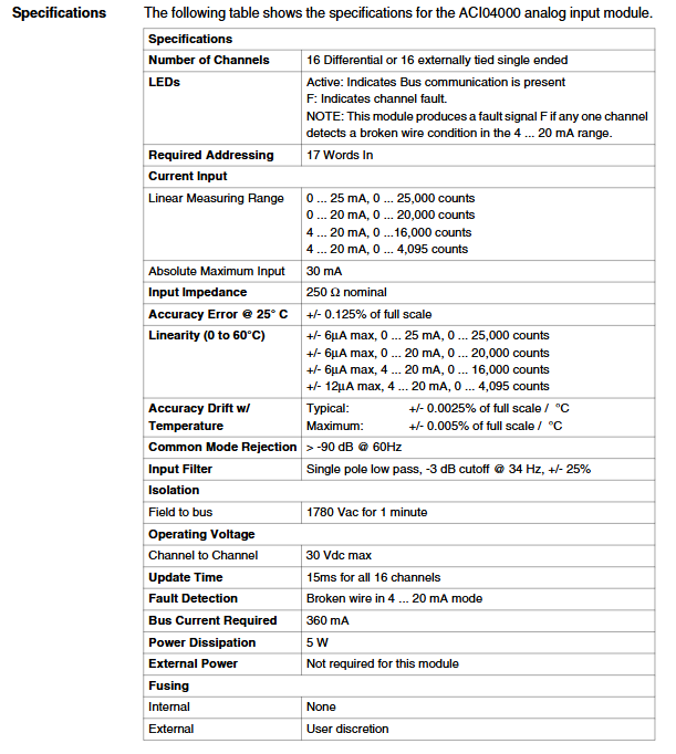
Analog input module (such as 140AVI03000)
Number of channels: 8 channels, supporting ± 10V/4-20mA signals
Accuracy: ± 0.05% full scale (25 ℃), resolution of 12 bits
Fault detection: wire breakage/over range alarm, LED red light indication
Analog output module (such as 140AVO02000)
Number of channels: 4 channels, output range ± 10V/0-5V
Output current: ± 10mA max, short circuit protection
Response time: 3ms (all channels are updated synchronously)
Discrete input module (such as 140DDI35300)
Voltage specification: 24 Vdc, 32 points (4 sets x 8)
Response time: 1ms (ON-OFF/Off ON)
Isolation level: 500 Vac between groups, 1 minute
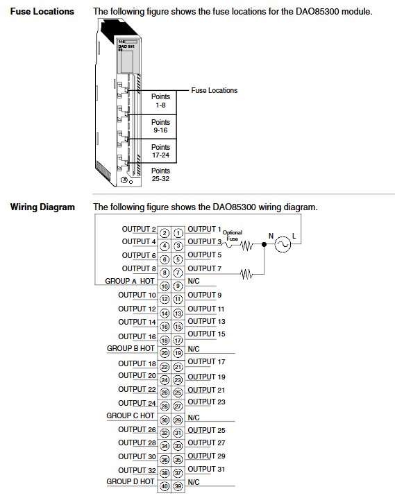
Discrete output module (such as 140DDO35300)
Output current: 0.5A/point, 4A/group
Protection function: overcurrent/short circuit protection, fuse 5A/group
Wiring method: Source/drain output optional
(3) General meaning of LED indicator lights
LED name, color, status, meaning
Active green bus communication is normal
External fault of F red module (disconnection/power shortage/overcurrent)
The green channel/point corresponding to 1-32 is in the ON state
1-32 red corresponds to channel/point faults (overcurrent/disconnection)
Hardware Installation Specification
(1) Mechanical installation requirements
Backboard selection: Supports 2-16 slots, such as 140XBP01600 (16 slots, 7.2kg)
Installation space: A heat dissipation gap of ≥ 100mm is reserved above and below the module, and the side spacing is ≥ 25.4mm
Tightening torque: Module fixing screws 2-4 in lbs (0.23-0.45 Nm), terminal screws 10 in lbs (1.13 Nm)
Bracket requirements: 125mm (front rail)/20mm (rear rail) installation bracket
(2) Power and grounding specifications
Grounding requirements: Each backplane should be individually grounded (green/yellow wire), with a grounding resistance of ≤ 4 Ω
Power configuration: AC power supply needs to be grounded with neutral wire, DC power supply should avoid reverse connection
Redundant power supply: Redundant modules must be of the same model, with a total load of ≤ N-1 module capacity (N is the number of modules)
CE compliance: Both ends of the shielded cable are grounded, and a filter (such as Schaffner FvN670-3/06) is installed on the power side
CableFast cabling system
(1) Types and Adaptation of Core Wiring Blocks
The terminal block model is suitable for I/O type core characteristics
140CFA04000 universal I/O point-to-point direct connection, compatible with most modules
140CFB03200 discrete input 32 point independent fuse (0.8A), anti single point fault
140CFH00800 analog input 8-channel, supports loop power supply, 0.063A fuse
140CFJ00400 analog output 4-channel, including monitoring terminal, 1/16A fuse
(2) Key parameters of wiring
Cable specifications: Control cable shielding layer thickness ≥ 0.2mm ², power line selection based on rated current
Maximum length: Analog signal 400m, discrete signal 1000m (shielded)
Wiring requirements: The power line and signal line should be laid in separate trenches with a spacing of ≥ 20cm
Fault diagnosis and maintenance
(1) Common types of faults and their solutions
Typical causes and solutions for fault phenomena
F LED is always on, disconnected/missing. On site power check wiring/power input
Channel no output overcurrent fuse/parameter error Replace fuse/reconfigure register
Communication interruption (Active light off) Bus looseness/address error check Bus connection/verify module address
(2) Maintenance points
Hot swappable: In addition to the power module, I/O modules can be plugged and unplugged with power on (the terminal block needs to be removed)
Parameter backup: configured through terminal panel or software backup module
Regular inspection: Check the wiring tightness, fuse status, and heat dissipation every 6 months
- YOKOGAWA
- Reliance
- ADVANCED
- SEW
- ProSoft
- WATLOW
- Kongsberg
- FANUC
- VSD
- DCS
- PLC
- man-machine
- Covid-19
- Energy and Gender
- Energy Access
- Renewable Integration
- Energy Subsidies
- Energy and Water
- Net zero emission
- Energy Security
- Critical Minerals
- A-B
- petroleum
- Mine scale
- Sewage treatment
- cement
- architecture
- Industrial information
- New energy
- Automobile market
- electricity
- Construction site
- HIMA
- ABB
- Rockwell
- Schneider Modicon
- Siemens
- xYCOM
- Yaskawa
- Woodward
- BOSCH Rexroth
- MOOG
- General Electric
- American NI
- Rolls-Royce
- CTI
- Honeywell
- EMERSON
- MAN
- GE
- TRICONEX
- Control Wave
- ALSTOM
- AMAT
- STUDER
- KONGSBERG
- MOTOROLA
- DANAHER MOTION
- Bentley
- Galil
- EATON
- MOLEX
- Triconex
- DEIF
- B&W
- ZYGO
- Aerotech
- DANFOSS
- KOLLMORGEN
- Beijer
- Endress+Hauser
- schneider
- Foxboro
- KB
- REXROTH
- YAMAHA
- Johnson
- Westinghouse
- WAGO
- TOSHIBA
- TEKTRONIX
- BENDER
- BMCM
- SMC
- HITACHI
- HIRSCHMANN
- XP POWER
- Baldor
- Meggitt
- SHINKAWA
- Other Brands
- UniOP
- KUKA
- IBA
- Beckhoff
- ADLINK
-
Beckhoff CP7232-0001-0030 - Control Panel PC HMI
-
Beckhoff CX5020-0122 - Embedded PC CPU Module
-
Beckhoff AM8043-0H10-0000 - Rotary Synchronous Servo Motor
-
Beckhoff CP3924-0010 - Multitouch Control Panel HMI
-
Beckhoff CX9020-0110-1005 - Embedded PC Basic CPU Module
-
Beckhoff BK9105 - EtherNet/IP Bus Coupler
-
Beckhoff CX1500-M310 - Profibus Master Fieldbus Extension Module
-
Beckhoff CX1500-M510 - PROFIBUS Master Fieldbus Extension Module
-
Beckhoff CP9922.0 - TTL-TX Display Transmitter Card
-
Beckhoff CP9010_1 - ISA Slot Interface Card
-
Beckhoff NRL75-DC30S15B - LCD Inverter Board
-
Beckhoff LTD121C30S - Toshiba LCD Display Panel
-
Beckhoff CP7732-1207-0030 - Operating Terminal Panel PC HMI
-
Beckhoff C5102-0010 - Rackmount Industrial Computer PC5000
-
Beckhoff C6015-0010 - Ultra-Compact Industrial PC
-
Beckhoff CB1056-0001 - Industrial PC Motherboard Mainboard
-
Beckhoff AX5103 - Digital Compact Servo Amplifier 1 Axis
-
Beckhoff AM8052-0J00-9000 - Rotary Synchronous Servo Motor
-
Beckhoff CP7932-0002-0000 - Control Panel HMI Display
-
Beckhoff CB1061-0001 - Industrial PC Motherboard Mainboard
-
Beckhoff C5102-0060 - 19-inch Rackmount Industrial PC
-
Beckhoff EL7342 - 2 Channel DC Motor Motion Interface EtherCAT Terminal
-
Beckhoff CX5120-0135 - Embedded PC CPU Module Intel Atom
-
Beckhoff CB1061-G4 - Industrial PC Motherboard Mainboard
-
Beckhoff CX50100121 - Embedded PC CPU Module
-
Beckhoff CX1030-0013-1002 - Basic CPU Module Intel Pentium M
-
Beckhoff CP7802-1075-0010 - Control Panel Touch Screen HMI
-
Beckhoff AM8023-0E20-0000 - Rotary Synchronous Servo Motor
-
Beckhoff EL5032 - 2 Channel Encoder Interface EnDAT EtherCAT Terminal
-
Beckhoff CX5130-0175 - Embedded PC CPU Module Intel Atom
-
Beckhoff CA4040-0000 - PCI Ethernet Network Board
-
Beckhoff C3340 - Panel PC Industrial Workstation
-
Beckhoff EL3068 - 8 Channel Analog Input EtherCAT Terminal 0-10V
-
Beckhoff EL1889 - 16 Channel Digital Input EtherCAT Terminal
-
Beckhoff C6640-0050 - Control Cabinet Industrial PC Intel Core i7
-
Beckhoff PC MIC 3230 TP - Industrial Panel PC Touch Screen
-
Beckhoff CX2040-0135 - Embedded PC Industrial CPU Module
-
Beckhoff CP6202-1020-0010 - Built-in Panel PC HMI
-
Beckhoff KL3001 - 1 Channel Analog Input Bus Terminal 0-10V
-
Beckhoff C6920-1047-0030 - Control Cabinet Industrial PC
-
Beckhoff CX5140-0122 - Embedded PC CPU Module
-
Beckhoff AX5106-0000-0200 - Digital Compact Servo Amplifier 1 Axis
-
Beckhoff EL2904 - 4 Channel Digital Output TwinSAFE EtherCAT Terminal
-
Beckhoff AM8053-1GH1-0000 - Rotary Synchronous Servo Motor
-
Beckhoff EL4021 - 1 Channel Analog Output 0-20mA Bus Terminal
-
Beckhoff CX5010-0121 - Embedded PC CPU Module
-
Beckhoff C6925-0020 - Control Cabinet Industrial PC
-
Beckhoff CX9010-N000 - Virtual Fieldbus Interface Module
-
Beckhoff CX9010-N031 - System Interface Module RS232
-
Beckhoff CX9010-N010 - System Interface Module DVI USB
-
Beckhoff CX9010-1101 - Basic CPU Module
-
Beckhoff CX8080 - Embedded PC Controller Module
-
Beckhoff C6909-0001-0000 - Built-in Control Panel HMI Touch Screen
-
Beckhoff ELM3502-0000 - 2 Channel Measuring Bridge EtherCAT Terminal
-
Beckhoff CX2040-0100 - Embedded PC CPU Controller Module
-
Beckhoff CX2072-0155 - Embedded PC Intel Xeon CPU Base Module
-
Beckhoff EL4732 - 2 Channel Analog Output EtherCAT Terminal Oversampling
-
Beckhoff CP6907-1000-000 - Built-in Control Panel Operator HMI
-
Beckhoff B310-0000 - Fieldbus Box PROFIBUS Interface
-
Beckhoff IP3112 - Fieldbus Box 4 Channel Analog Input PROFIBUS
-
Beckhoff AM8023-0F21-0000 - Rotary Synchronous Servo Motor
-
Beckhoff AX2090-L805-0001 - Shield Connection Motor Module
-
Beckhoff AM8053-0L2B-0000 - Rotary Synchronous Servo Motor
-
Beckhoff CP7803-0011-0010 - Control Panel HMI Display
-
Beckhoff CP2919-0000 - Multi-Touch Built-in Control Panel HMI
-
Beckhoff CX5020-0125 - Embedded PC CPU Module
-
Beckhoff CP3924-000 - Multitouch Control Panel HMI
-
Beckhoff C6930-0040 - Control Cabinet Industrial PC Core i5
-
Beckhoff CX5020-0121 - Embedded PC CPU Module
-
Beckhoff CX5020-0100 - Embedded PC CPU Module
-
Beckhoff CX1030-0121 - Basic CPU Module Intel Pentium M
-
Beckhoff EP2349-0021 - EtherCAT Box Multi Directional Digital I/O
-
Beckhoff CX1020-0012 - Basic CPU Module
-
Beckhoff CP6929-0001-0000 - Built-in Control Panel Touch HMI
-
Beckhoff CX9020-0115 - Standard PLC Module CPU Unit
-
Beckhoff CP7803-0001-0010 - Control Panel HMI Display
-
Beckhoff CX1900-0025 - Compact Flash Memory Card
-
Beckhoff HUSKY PC#6 - Industrial PC Sercos Card Interface
-
Beckhoff EK1818-0000 - EtherCAT Coupler Digital Input Output Module
-
Beckhoff EL4112-0010 - 2 Channel Analog Output EtherCAT Terminal
-
B&R 4P3040.01-490 - Control Panel HMI
-
B&R 5PC600.SX05-01 - Industrial Computer System Unit
-
Beckhoff CX5130-0121 - Embedded PC CPU Module
-
Beckhoff C6515-1001-0000 - Fanless Built-in Industrial PC
-
Beckhoff AX5106-0000-0200 - Digital Compact Servo Amplifier 1 Axis
-
Beckhoff CP6829-0001-0000 - Built-in Control Panel Touch HMI
-
Beckhoff CX2040-0100 - Embedded PC CPU Quad Core Module
-
Beckhoff CX5140-0175 - Embedded PC CPU Module Intel Atom
-
Beckhoff EK1322 - 2 Port EtherCAT P Junction Module
-
Beckhoff C6650-0020 - Control Cabinet Industrial PC
-
Beckhoff C6525-0030 - Fanless Built-in Industrial PC
-
Beckhoff CP7232-0002-0020 - Control Panel PC HMI
-
Beckhoff CP2916-0000 - Multi-Touch Control Panel HMI Display
-
Beckhoff C6920-0050 - Control Cabinet Industrial PC
-
Beckhoff EL2828 - 8 Channel Digital Output EtherCAT Terminal
-
Beckhoff AX5103-0000-0200 - Digital Compact Servo Amplifier 1 Axis
-
Beckhoff CX2020-0121 - Embedded PC CPU Module
-
Beckhoff CP3918-1012-0000 - Multitouch Control Panel HMI
-
Beckhoff FC3101 - Profibus PCI Fieldbus Interface Card
-
Beckhoff C6220 - Control Cabinet Industrial PC
-
Beckhoff CX9020-0111 - Embedded PC CPU Module Base Unit
-
Beckhoff CP6911-0001-0000 - Installation Control Panel HMI
-
Beckhoff CX2100-0004 - Power Supply Module E-bus Coupler
-
Beckhoff CP6700-0500 - Built-in Panel PC Touch Screen HMI
-
Beckhoff CP7902-1235-0000 - Control Panel Touch Screen
-
Beckhoff CB3054-0001 - Industrial PC Motherboard
-
Beckhoff CX1020-N031 - System Interface Module
-
Beckhoff CX1100-0002 - Power Supply Module
-
Beckhoff CX1020-0100 - Basic CPU Module
-
Beckhoff C6032-0060 - Ultra-Compact Industrial PC
-
Beckhoff C6140 - Control Cabinet Industrial PC Intel Celeron
-
Beckhoff CX5120-0111 - Embedded PC CPU Module
-
Beckhoff CP6202-0001-0010 - Built-in Panel PC HMI
-
Beckhoff CP6222-0001-0030 - Built-in Panel PC HMI
-
Beckhoff CP6706-0001-0050 - Built-in Panel PC HMI
-
Beckhoff C6017-0010 - Ultra-Compact Industrial PC
-
Beckhoff CP6202-1029-0020 - Built-in Panel PC HMI
-
Beckhoff AX5805 - TwinSAFE Drive Option Card
-
Beckhoff AX5206-0000-0202 - Digital Compact Servo Amplifier 2 Axis
-
Beckhoff CP2216-0010 - Multi-Touch Built-in Panel PC HMI
-
Beckhoff C6920-0060 - Control Cabinet Industrial PC
-
Beckhoff CX1020-0011 - Basic CPU Module
-
Beckhoff CX2900-0033 - Solid State Disk SSD Storage
-
Beckhoff CX1800-2031 - System Module Extension
-
Beckhoff CX2020-0120 - Embedded PC CPU Module
-
Beckhoff CP3921-1113-0010 - Multitouch Control Panel HMI
-
Beckhoff CP7701-0001-0020 - Panel PC Touch Screen AMD LX
-
Beckhoff CX5020 - Embedded PC CPU Module

K-JIANG

Add: Jimei North Road, Jimei District, Xiamen, Fujian, China
Tell:+86-15305925923