
K-WANG


Zygo Device Standard Operating Procedure (SOP)
Emergency operation: If an abnormality occurs, immediately press the "Emergency Off" button on the motion controller, and the device will need to perform the "Homing" operation again in the future.
Zygo Device Standard Operating Procedure (SOP)
Core operating prerequisites and safety warnings
Core safety mechanism: The Z-axis limit (Z-stop) of the Motion Controller is a critical safety protection, and it must be confirmed that it has been set (the indicator light is constantly green or red) before all measurement steps to prevent collision between the objective lens and the sample/stage.
Emergency operation: If an abnormality occurs, immediately press the "Emergency Off" button on the motion controller, and the device will need to perform the "Homing" operation again in the future.
Complete operational process
1. Startup and initialization (Start Up)
(1) Inspection of motion controller
Confirm Z-stop status: The indicator light should be constantly on green/red. If it flashes red and accompanied by a beep, it needs to be reset (detailed steps to follow).
Familiar with controller functions:
Precautions for functional operation mode
When the Z-axis objective lens moves and rotates the Joystick near the sample or at high magnification, use low speed (adjusted by the "+/-" keys)
XY axis stage movement tilt control lever (need to select the "XY" button, corresponding green light on) is used for rough positioning of the sample to ensure that the objective beam is projected onto the sample
Pitch/Roll (P/R) adjustment tilt control lever (the "PR" button needs to be selected, corresponding green light is on) P (pitch), R (roll) maximum adjustment range ± 2 °, θ (rotation) function is invalid
(2) Software startup and application loading
Login to the computer: Enter the username "Zygo" and press Enter to enter the system.
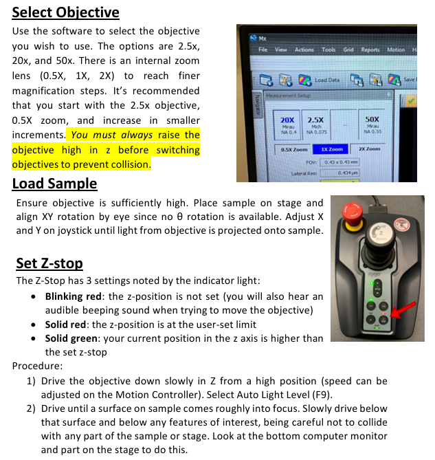
Open the Mx software: Start the Mx program from the desktop, go to "File" ->"Load Application", and load the "Micro. appx" application (the application list also includes other. appx files such as roughness measurement and low-pass filtering, which need to be selected accurately).
Instrument parameter initialization: After loading the application, a "F-stop/A-stop" setting window will pop up. Please confirm:
F-stop (aperture): in the "Open" state (locked by pressing the knob);
A-stop (aperture stop): in the "Open" state (locked by pressing the knob);
Filter: Set to "F1 (Measure)", click "OK" to confirm.
2. Sample and objective lens preparation
(1) Objective selection and switching
Optional objective lenses: 2.5X (NA 0.075), 20X (NA 0.55), 50X, paired with an internal zoom lens (0.5X/1X/2X) for fine magnification adjustment.
Switching principle:
Initial recommendation is to use a "2.5X objective lens+0.5X zoom" and gradually increase the magnification (to avoid collisions caused by using high magnification directly);
Before switching the objective lens, it must be raised to the highest position along the Z-axis to prevent collision with the sample.
(2) Load Sample
Confirm that the objective lens has been raised to a high position and place the sample on the stage;
Roughly adjust the XY direction rotation of the sample with the naked eye (the device does not have a θ rotation function);
Tilt the XY joystick and move the stage until the beam emitted by the objective lens is projected onto the surface of the sample.
(3) Z-stop setting (core security steps)
Slowly lower the objective lens from the Z-axis high position (adjust the controller speed, slightly faster in the initial stage, and slow down when approaching the sample), press "F9" to start "Auto Light Level";
Continue to lower the objective lens until the sample surface is roughly in focus, and then slowly lower it to the position of "all features below the target measurement area" (combined with the display below and visual observation to avoid collision);
Press the "Z-stop" button on the motion controller, and the indicator light will change from flashing red to constantly on red, completing the setting (at this time, the lowest position of the Z-axis is locked).
3. Calibration before measurement (optimizing pitch/roll)
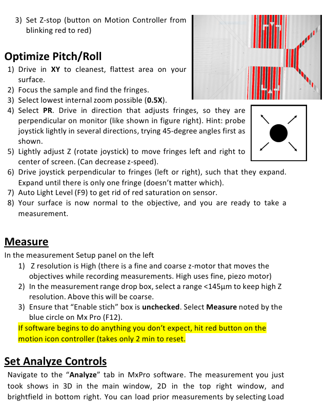
By adjusting the P/R (pitch/roll), ensure that the sample surface is perpendicular to the objective lens. The steps are as follows:
Move the XY stage to move the "smoothest and cleanest area" of the sample directly below the objective lens;
Focus on the sample and find the interference fringes, switch to the lowest internal zoom (0.5X) for easy observation of the fringes;
Select the "PR" button (green light on), lightly touch the joystick (try 45 ° direction first), and adjust the stripes to be perpendicular to the monitor;
Fine tune the Z-axis (rotate the joystick to reduce speed) and move the stripes to the center of the screen;
Tilt the joystick in the direction perpendicular to the stripes to expand them until only one stripe remains on the screen (direction not limited);
Press "F9" again to perform automatic light intensity adjustment, eliminate sensor red saturation, and complete calibration.
4. Perform Measurement
(1) Measurement parameter settings
Configure in the left "Measurement Setup" panel:
Z resolution: set to "High" (enable fine piezoelectric motor to ensure accuracy);
Measurement Range: Select a range of<145 μ m (if exceeded, it will automatically switch to coarse precision mode);
Enable Stitch function: Uncheck (default off to avoid multi area stitching errors).
(2) Start measurement
Click the blue "Measure" button in the Mx software (or press "F12");
Exception handling: If the software performs an unexpected operation, immediately press the red emergency button on the motion controller to reset the device (approximately 2 minutes).
5. Data Processing (Set Analyze Controls)
After the measurement is completed, the data will be displayed in "3D view (main window), 2D view (upper right window), bright field image (lower right window)", and horizontal correction needs to be performed through post-processing:
(1) 2D horizontal correction (applicable for profile analysis)
Right click on the 3D image in the main window and select "2D" to switch views;
Select the "Linear" option at the top of the window, click on two points on the image, and determine the profile to be analyzed (the profile curve will be automatically generated below);
Right click on the profile curve and add "Inspector 1" and "Inspector 2" in sequence;
Move the Inspector to the baseline surface, right-click and select "Level" to complete the calibration.
(2) 3D horizontal correction (applicable to overall surface analysis)
In the "Surface" panel on the left, click on "Surface Processing" (a settings window will pop up);
Check the "Immediate Update" and "Use Fit Mask" options in the bottom left corner, and click on "Mask Editor";
Check 'Form Remove' and draw a geometric shape to frame the surface shape to be removed (such as protrusions and depressions);
Close the "Mask Editor" and "Surface Processing" windows, and the correction effect will be automatically applied to the 3D data.
6. Save Results&Clean Up
(1) Save Results
Raw data (. datax format): Use "File" → "Save Data" to save to the "Data (D:) ZygoData" folder on drive D;
Image/Table Export: Right click on any chart and select "Export" to export the image as an image format or the 2D section as a. csv file.
(2) Shutdown process
Raise the objective lens: Raise the objective lens to the highest position along the Z-axis and reset the Z-stop (press the button until the indicator light stays on in red);
Software and System Shutdown: Close the Mx software, exit the "Zygo" account, and turn off the monitor;
Record and report: Sign in the experimental log book. If any errors occur during use, take a screenshot and save it to the data folder, and indicate the fault situation in the log.
Key precautions
Collision protection: All operations involving Z-axis movement (switching objectives, loading samples, setting Z-stop) must ensure sufficient safety distance between the objective and the sample, and prioritize the lowest speed when high magnification (50X);
Magnification selection logic: Starting from low magnification (2.5X+0.5X), gradually increasing to avoid using high magnification directly causing "sample not found" or collision;
Data storage standard: The. datax original file should be named with "sample name+date", and screenshots and. csv files should be associated with the original data for easy traceability in the future;
Priority of exception handling: In case of equipment failure, press the emergency button first, and then record the fault phenomenon (screenshot+text description). It is prohibited to disassemble or modify software parameters by oneself.
- YOKOGAWA
- Reliance
- ADVANCED
- SEW
- ProSoft
- WATLOW
- Kongsberg
- FANUC
- VSD
- DCS
- PLC
- man-machine
- Covid-19
- Energy and Gender
- Energy Access
- Renewable Integration
- Energy Subsidies
- Energy and Water
- Net zero emission
- Energy Security
- Critical Minerals
- A-B
- petroleum
- Mine scale
- Sewage treatment
- cement
- architecture
- Industrial information
- New energy
- Automobile market
- electricity
- Construction site
- HIMA
- ABB
- Rockwell
- Schneider Modicon
- Siemens
- xYCOM
- Yaskawa
- Woodward
- BOSCH Rexroth
- MOOG
- General Electric
- American NI
- Rolls-Royce
- CTI
- Honeywell
- EMERSON
- MAN
- GE
- TRICONEX
- Control Wave
- ALSTOM
- AMAT
- STUDER
- KONGSBERG
- MOTOROLA
- DANAHER MOTION
- Bentley
- Galil
- EATON
- MOLEX
- Triconex
- DEIF
- B&W
- ZYGO
- Aerotech
- DANFOSS
- KOLLMORGEN
- Beijer
- Endress+Hauser
- schneider
- Foxboro
- KB
- REXROTH
- YAMAHA
- Johnson
- Westinghouse
- WAGO
- TOSHIBA
- TEKTRONIX
- BENDER
- BMCM
- SMC
- HITACHI
- HIRSCHMANN
- XP POWER
- Baldor
- Meggitt
- SHINKAWA
- Other Brands
- UniOP
- KUKA
- IBA
- Beckhoff
- ADLINK
-
Beckhoff CX1100-0910 - Power Supply Module
-
Beckhoff C5210-0010 - Communication Module C5210
-
BECKHOFF KL1352 - Bus Terminal SET OF 2 FREE FAST SHIP
-
Beckhoff EL3058 - 8 x analog input single ended 4...20mA 85惟 shunt 12bit
-
Beckoff CX1100-0920 - UPS Module 24VDC (US SELLER) * *
-
BECKHOFF C6920-0000 - C69200000 PLC Moudule
-
Beckhoff CX5120-0115 - CPU controller module CX5120-0115
-
Unknown 15F5C1E-Y50A - Of Frequency Converters
-
Beckhoff AX5118-0000-0200 - Servo Drive HTP0
-
BECKHOFF AX5106-0000-0200 - Servo Drive
-
Beckhoff CX5240-0175 - Module (free) #U2327D YG
-
Beckhoff CP6607-0001-0000 - Compact PC Panel Economy Installation Operator 5,7 "
-
Beckhoff EP3744-0041 - 2022 EP37440041 Module
-
Beckhoff CP6209-0001-0020 - 6.5" PC Touch Screen Control Panel 24VDC
-
Beckhoff CX9020-0111 - /U900 +8x+2xEL3121+1x EL9410+3xEL1008+1x EL2008 Set
-
Beckhoff C6525-1030-0050 - Industrial PC
-
Beckoff CX1100-0920 - UPS Module 24VDC (US SELLER)
-
Beckhoff CX5010-0120 - CX5010 Processor Intel Atom Z510 B24
-
Siemens 6FC5203-0AF04-1BA1 - Operation Panel
-
Beckhoff CX5230-0175 - / 000029724 Embedded PC / Industrial PC on Rail
-
Beckhoff CP3916-0000 - industrielles Anzeige- und Bedienterminal
-
BECKHOFF CX1500-M310 - CX1000-N000 CX1000-0011 CX1000-C00L CX1100-0002 PLC Module
-
Beckhoff EL1872 - 16-channel digital input terminal
-
BECKHOFF EP2318-0001 - module
-
Beckhoff CX9020-0110 - Basic CPU Module
-
Beckhoff EL2564 - EtherCAT Terminal, 4-channel LED output, 5鈥?8VDC, 4A, RGBW
-
Beckhoff CX5130-0155 - /000105637 Automation Embedded PC
-
B&R 400 - Power Control Panel Rev D0 24 VDC
-
Beckhoff CX2020-0155 - module
-
Beckhoff CX9020-0115 - PLC Module
-
BECKHOFF EL6695 - PLC EL 6695
-
BECKHOFF EL7047 - PLC Modules
-
Beckhoff CX1000-0012 - Control HW 2.2 + CX1500-M310 + CX1000-C00L + CX1100-0002+
-
Beckhoff C6920-1039-0030 - control cabinet industrial PC CPU Celeron 1.90 GHz, 2 cores
-
BECKHOFF CX1100-0910 - PLC Module#
-
Beckhoff IL2301-B318-0000 - Coupler Box 4 Channel Digital Input |
-
Beckhoff CX7080 - Module
-
Beckhoff C6930-0060 - Industrial PC
-
Beckhoff CP7902-1060-0000 - Touchscreen 15 " CP7902
-
beckhoff CX9020-0111 - Controller module or UPS
-
Beckhoff CX8091 - PLC Module CX8091
-
Beckhoff C6640-1008-0030 - Control Cabinet Industrial PC
-
BECKHOFF CX1100-0920 - module
-
Beckhoff C9900-M921 - see pictures
-
BECKHOFF CP6829-0001-0000 - Touch Panel
-
BECKHOFF C6930-0060 - Industrial Computer
-
BECKHOFF CX8050 - PLC module
-
Beckhoff CP6202-0021-0020 - Touch Screen #
-
BECKHOFF AM3031-0C20-0000 - SERVO MOTOR
-
Unknown BCH1302N11A1C - Servo motor
-
Beckhoff EL2502 - 2-channel pulse width output terminal
-
Beckhoff EL6731 - Profibus Master / *Rev: 0025
-
Beckhoff CP3918-0010 - Control Panel
-
BECKHOFF CP2915-0010 - [24 MONTH WARRANTY] Control Panel
-
Beckhoff AX5203-0000-0202 - Servo Drive
-
Schneider TSXDSY64T2K - PLC OUTPUT MODULE
-
Beckhoff EP4174-0002 - Module-
-
Beckhoff IL2302-B318-0000 - Profibus Box
-
Beckhoff CP6709-0001-0000 - Touchpanel
-
BECKHOFF CX2030-0123 - Controller
-
Beckhoff CX9020-0111 - Processor Module
-
Beckhoff CX1020-0000 - CX Basic CPU Module
-
Beckhoff AX2003-AS - Servo Drive HTP0
-
Beckhoff C6240-1052-0040 - 4-086-06-3073 Industrial Computer CB1052-0003
-
Beckhoff EL1918 - 8 xTwinSAFE Input
-
Beckhoff AM8072-0R20-0000 - Servomotor
-
BECKHOFF AM8021-1B21-0000 - servo motor #T882 YS
-
Beckhoff EL6224 - 4 X Terminal IO-LINK
-
Beckhoff CX5140-0135 - embedded PC with Intel Atom processor 4 GB HW 3.6
-
Beckhoff CP7201-1000-0000 - Panel PC #
-
Beckhoff CX5130-0121 - Embedded-PC 4GB CPU Module HW 2.5 Industrial PC
-
Beckhoff AM8022-0D41-1002 - Servomotor
-
BECKHOFF CX2030-0130 - Module
-
BECKHOFF EL1872 - 16-channel digital input terminal
-
Unknown GXMMW.A203P33 - 1pc encoder
-
Beckhoff EL6631-0000 - EtherCAT Terminal 2-Port EL 6631
-
BECKHOFF C6925-0030 - Industrial Computer
-
Beckhoff CX8190 - A Module
-
BECKHOFF CX2040-0135 - CX2040-0135/000000927 CPU BASE MODULE i7 2715QE 2.1GHz --
-
BECKHOFF KL6023-0000 - Wireless adapter
-
Saia Burgess PCD7.F700 - PCD7F700 Communication Module
-
Beckhoff CX5130-0112 - CPU Module
-
BECKHOFF CX1020-N010 - CX1020-N000 CX1020-0111 CX1100-0004 EL2008 EL3064 EL4004
-
Beckhoff EP1819-0021 - A Module
-
Beckhoff CX2030-0120 - / 4gb with CX2100 0004
-
B&R X20-XC-0292 - Automation Powerlink Ethernet Bus Controller Module
-
Beckhoff BK3110 - One PLC Module
-
BECKHOFF KL3222 - PLC Module
-
BECKHOFF CX1500-M310 - CX1000-N000 CX1000-0011 CX1000-C00L CX1100-0002 PLC MODULE
-
Beckhoff CP3918-0010 - Control Panel
-
Beckhoff CX2030-0100-1002 - /4GB + CX2100 + CX2550 + CX2500-0060 + SSD
-
Beckhoff EP1816-0008 - PLC Module
-
Beckhoff CX5130-0112 - Module
-
Beckhoff Cx1500-m750 - CPU Hw: 1.4
-
BECKHOFF AX5112-0000-0200 - AX511200000200 Servo Driver
-
Beckhoff EL3751 - EtherCAT Terminal 1 Channel Analog Input Multifunction 24 Bit
-
Beckhoff CX1100-0002 - Power Supply Module
-
Beckhoff CP3916-1016-0010 - Control Panel
-
BECKHOFF CX9001-1101 - #NAME?
-
Beckhoff EP3174-0002 - EtherCAT Box Module
-
Beckhoff C6030-0070 - servo drive
-
Beckhoff CX2020-0120 - /4GB CPU, CX2100-0904, 3x EL6900, EL1904, 16GB Memory
-
BECKHOFF C6110 - BOX-PC 113608
-
BECKHOFF EK1914 - module #P
-
Beckhoff C6140 - Ipox IP-4GVI63 + CH7009A_DVI_TV + SIEMENS A5E00369843 + WD800AAJB
-
Beckhoff CX5020-0111 - controller Good quality
-
BECKHOFF C6015-0010 - / 6559380 ULTRA-COMPACT INDUSTRIAL PC ()
-
Beckhoff AX5203-0000-0200 - PLC module
-
Beckhoff EL2872 - 16-channel digital output terminal
-
BECKHOFF C3640-0000 - Panel Industrial PC 100/240VAC 128MB E0122L
-
Beckhoff CX8031 - Module
-
Beckhoff CX5020-0120-1002 - PLC module#
-
Beckhoff C6140 - M845B + SIEMENS A5E00369843 + C9900_A159_1 + AUTOMATA CAN PCI 1N
-
BECKHOFF AX5112-0000-0200 - Servo Drive*ie
-
B&R ECPA42-01 - Analog Output Module 4-Channel, +/- 10V Output Signal, 20mA Max
-
Beckhoff EL6631-0010 - PLC Module
-
BECKHOFF C6930-0070 - CONTROL CABINET INDUSTRIAL PC
-
BECKHOFF AX5112-0000-0200 - AX511200000200 Servo Driver
-
BECKHOFF EK9000 - Programmable Logic Controller Module EK9000 EK9000
-
BECKHOFF C6920-1028-0000 - Industrial computer
-
Beckhoff CX2030-0120 - controller Module
-
Beckhoff BX8000-0000 - Bus Terminal Controller HW 4.4
-
B&R 3NC154.60-2 - Positioning Module#
-
BECKHOFF CX1020-0122 - PLC module
-
Beckhoff AM3032-0D40-0000 - Servo Motor
-
BECKHOFF CX5020-0111 - CPU Module CX5020-0111
-
Beckhoff CB1051 - G5 Motherboard
-
BECKHOFF KL2641 - 1-channel relay output terminal

K-JIANG

Add: Jimei North Road, Jimei District, Xiamen, Fujian, China
Tell:+86-15305925923