
K-WANG


ZYGO MetroPro 9.0 Reference Guide (OMP-0347M)
Version history: From version 4.0 in 1993 to version 9.0 in 2011, the manual revision records cover functional updates in each version (such as the addition of FDA high-resolution analysis in version 7.10 and optimized pattern editor in version 8.0).
ZYGO MetroPro 9.0 Reference Guide (OMP-0347M)
Software Fundamentals and Core Architecture
1. Basic Information and Document System
Software positioning: Suitable for Zygo precision optical measurement equipment, providing data acquisition, analysis, visualization, and automation functions, supporting custom application configuration to adapt to different measurement scenarios (such as surface morphology, roughness, wavefront analysis).
Version history: From version 4.0 in 1993 to version 9.0 in 2011, the manual revision records cover functional updates in each version (such as the addition of FDA high-resolution analysis in version 7.10 and optimized pattern editor in version 8.0).
2. Software architecture and hierarchical logic
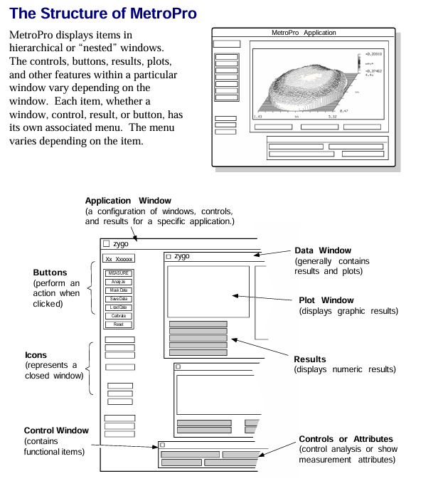
MetroPro adopts a nested window structure, with each component nested in a hierarchical order of "MetroPro main window → application window → function window (control/data/drawing, etc.)". The core components are defined as follows:
Component Type Core Function Example
The top-level interface of MetroPro main window software after startup, which can load/create multiple application windows and display loaded application icons (such as Micro. app)
Application Window is a set of configurations for specific measurement tasks, including sub windows for surface morphology measurement applications such as control and data (including objective control and data display windows)
Control Window manages measurement parameters (such as laser power, scanning mode), triggering operations (measurement/calibration), including the "MEASURE" button and laser intensity control slider
The Data Window displays measurement data, supports plotting (3D/profile), and displays numerical results including filled plots and profile result tables
Plot Window data visualization tools, such as fill plots (surface morphology), profile plots (2D contour), 3D model plots, power spectral density plots (PSD)
Controls/Buttons control parameter adjustment (such as filter type, unit selection), trigger specific function "Auto Focus" button, "Filter Type" dropdown control
3. Basic operating standards
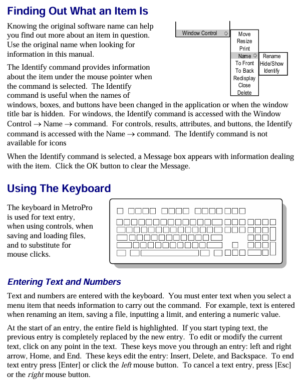
Keyboard and Mouse Operations:
Shortcut keys: F1 triggers measurement, F5 automatically adjusts light intensity, Ctrl+Alt+Delete exits software;
Mouse functions: right-click to bring up menus, middle click to move windows, left click to select/trigger (such as button clicking, text input).
File Management
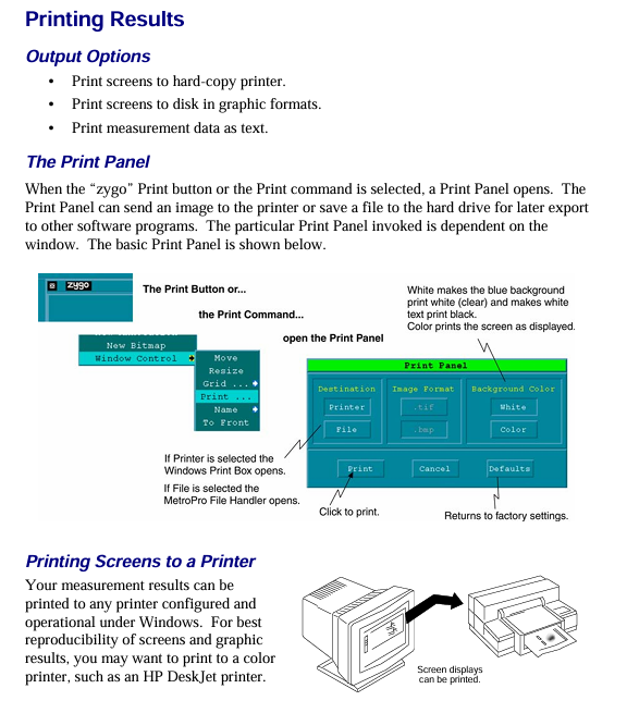
Supports 10 core file formats, including application configuration (. app), measurement data (. dat), mask (. mas), script (. scr), etc;
File naming convention: The first character is a letter/number, supporting underscores and periods, with a maximum length of 20 characters (after version 7.4). It is recommended to add an extension (such as "Sample01. dat");
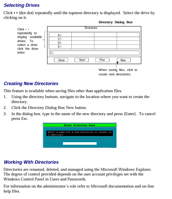
Directory operation: Create/switch directories through the "File Handler" dialog box, supporting cross drive file access.
Window Control: Supports window movement, scaling, cascading, and closing (converted to icons), and can be hidden, renamed, deleted, and other operations through the "Window Control" menu.
Detailed explanation of core functional modules
1. Working with Applications
The application is the core task unit of MetroPro, which can be customized to meet different measurement needs. The core operations include:
(1) Application type and loading
Type classification:
Standard application: Pre installed software (such as "Micro. app" for microscopic measurement), write protected, needs to be copied and modified through the user directory;
Custom application: Modify based on existing applications (such as adjusting control positions, adding new drawings) or create from scratch.
Loading process: Right click on the MetroPro main window menu ->"Load Application", select the. app file in the file browser, and support loading multiple applications simultaneously (up to 3 can be opened at the same time).
(2) Application configuration and saving
Core component configuration:
Control window: Add measurement parameter controls (such as objective lens selection, scan length), function buttons (such as "Calibrate" calibration);
Data window: Add plots (such as fill plots, profile plots), result value boxes (such as PV values, RMS values);
Other windows: Report window (generate measurement report), Video monitoring window (real-time display of measurement area).
Save rules:
Save Application ": Specify a name and path when saving for the first time (such as" Customs Surface. app ");
Re save Application ": Overwrite the current application configuration without the need to reselect the path;
Lock application: Press Ctrl+Shift+L to lock the application (to prevent accidental changes), supports password protection (4-13 letters/numbers).
2. Mask Editor
Masks are used to define measurement areas (including/excluding specific areas), supporting 4 types of masks and adapting to different measurement scenarios:
(1) Mask type and function
The core role of mask types in application scenarios
Default (default mask) takes effect by default when no other masks are defined for regular measurements, covering the entire camera field of view
Eliminate interference areas (such as edge diffraction and low reflectivity areas) during the data acquisition phase of the Acquisition mask to reduce data volume and improve speed
Test/Reference Mask Area Comparison Measurement defines "test area" and "reference area", used for analyzing differences in different areas of the same part (such as surface flatness comparison)
(2) Mask creation and editing
Basic operation: Click the "Mask Data" button to open the editor, which supports drawing shapes such as circles, rectangles, polygons, etc. Use "Fill/Fill" to control whether the area is included in the analysis (the filled area is the valid area);
Advanced features:
Auto Aperture: Automatically generate circular/rectangular masks based on data, and can set the center position (such as data centroid, fixed coordinates) and the ratio of inner and outer diameters;
Fiducials: Define reference marker points for aligning parts (such as position calibration when assembling multiple data sets), and support saving as. gid files for reuse.
3. Pattern Editor
For instruments with programmable motor stages, used to define automatic measurement position sequences, supporting 3 types of pattern types:
(1) Pattern type and parameters
Pattern type applicable scenario core parameters
Rectangular regular array measurement (such as multiple chips on a wafer) includes row/column count, row/column spacing, and motion sequence (snake/grating)
Circular area measurement (such as lens surface) includes the number of circles, the number of radial points, and the radius range (Radius 1/Radius 2)
Free Rect irregular position measurement manual addition/editing of position coordinates, supports online (capturing position after stage movement)/offline (directly inputting coordinates) creation
(2) Pattern operation and control
Run settings: Specify the operation (measurement/run script), pause time (Pre Pause/Post Pause), and error handling (retry/skip/terminate) for each location;
Position management: Edit the position (including/excluding specific points) through the "Position Editor", and view the measurement status of each position through the "Position Status" (identified by code: P=qualified, F=failed,?)? =Unmeasured).
4. Drawing function (Filled Plot&Profile Plot)
Drawing is the core of data visualization, and the most commonly used "Filled Plot" and "Profile Plot" are used in conjunction to cover 3D surfaces and 2D contour analysis
(1) Filled Plot
Functional positioning: Display 3D surface morphology and distinguish height differences by color (such as spectral colors representing different height ranges);
Controller function:
Color settings: Supports 16 color bands, grayscale, CMYK, and other color schemes. "Color Fit" optimizes the display of data with a high proportion of a single color;
Slice tool: Draw linear/radial/circular slices, define the analysis path of the cross-sectional view;
Show PV: Mark the highest (Peak) and lowest (Valley) points on the surface to display the PV value;
Limit display: Combined with the upper and lower limits of PV results, it is highlighted in red when exceeding the limit.
(2) Profile Plot
Function positioning: Display the 2D height contour on the slicing path, support precise numerical analysis;
Core operation:
Axis scaling: Fixed X/Y axis range (such as Y-axis set to 0-100nm), or automatically adapted to data range;
Inspection tool: Move the crosshair to read the coordinates of any point (X=distance, Y=height), calculate the distance between two points (xDst) and the height difference (yDst);
Result export: Export profile data as text (CSV/Tab separated) or images (BMP/CIF).
5. Instrument Control
Covering key operations such as equipment calibration, error correction, and light intensity adjustment to ensure measurement accuracy:
(1) Automatic function
Auto Focus: Suitable for devices with a Z-axis motor, set the focus range through "Focus Max Adjust" and the minimum modulation threshold through "Focus Min Mod" to ensure focus accuracy;
Auto Tilt: For platforms with pitch/roll motors, adjust the angle of the parts to reduce stripe tilt, and set the "Auto Tilt Iterations" adjustment frequency (recommended 2-3 times to ensure convergence);
Auto null: Used for measuring spherical parts, adjusting the X/Y/Z axes to minimize interference fringes, requires inputting the nominal radius of curvature (RadCrv) of the spherical surface.
(2) Calibration and Error Correction
Lateral Calibration:
Purpose: To establish a correspondence between camera pixels and actual length (e.g. 1 pixel=2.5 μ m), Zygo standard calibration parts are required;
Process: Draw a calibration line in the "Lateral Calibrator" window, enter the actual length (such as 1mm), and save the calibration parameters;
System Error Correction:
Method: Measure high-precision standard components (such as reference planes with ≤ 2 Å RMS), save them as a system error file (. dat), and enable error subtraction through the "Abstract Sys Err" control;
Applicable scenarios: Eliminate the inherent aberrations of the instrument (such as optical system errors in interferometers) and improve measurement accuracy.
(3) Light intensity control
Manual adjustment: Press F4 to open the light intensity window, use the+/- (fine) and */(coarse) keys to adjust, ensuring that the saturation pixels are below the threshold (default ≤ 4);
Automatic adjustment: Press F5 to start AGC (automatic gain control), automatically adapt the reflectivity of the parts, optimize the signal-to-noise ratio, and set the "Target Range" with a safety margin for light intensity saturation (default 0.1).
Data processing and result output
1. Data format and conversion
Support import/export of multiple data formats, suitable for different analysis scenarios:
Binary format:. dat (raw measurement data, including phase/intensity matrix),. app (application configuration),. mas (mask);
Text formats:. csv (comma separated, used for Excel analysis),. rep (report file),. zfr (Zernike polynomial, CODE V format);
Universal format: Supports interaction with optical design software, such as CODE V (. wfr/. sur), ZEMAX (grid height data), OSLO compatible files.
2. Results and Reports
Result types: covering surface morphology (PV, RMS, Ra), wavefront analysis (Zernike coefficient, Seidel coefficient), geometric parameters (curvature radius, tilt angle), etc., supporting custom result units (imperial/metric/optical units such as wavelength);
Report generation:
Report Window: Add result values, attributes (such as measurement time, operator ID), and comment text, and save them as. rp files;
Q-DAS report: compatible with Q-DAS quality analysis system, supporting Gage Type 1/3 studies (measurement system repeatability analysis), outputting. dfq (merged files) or. dfd/. dfx (split header/data files).
Key Terminology Annotations
QPSI ™: Zygo's patented fast phase-shift interferometry technology, with a shutter speed of 5ms, strong anti vibration ability, and no need for complex isolation;
FDA (Frequency Domain Analysis): Frequency domain analysis technology used in white light scanning interferometers to extract multi wavelength phase information through Fourier transform and solve the 2 π phase ambiguity problem;
Zernike Polynomials: Used for fitting wavefront errors, MetroPro supports 37 terms (Coef 0-Coef 36) and can be exported in CODE V format;
BRDF(Bidirectional Reflectance Distribution Function): Bi directional reflection distribution function, used to analyze surface reflection characteristics, requires input of incident angle and scattering angle.
- YOKOGAWA
- Reliance
- ADVANCED
- SEW
- ProSoft
- WATLOW
- Kongsberg
- FANUC
- VSD
- DCS
- PLC
- man-machine
- Covid-19
- Energy and Gender
- Energy Access
- Renewable Integration
- Energy Subsidies
- Energy and Water
- Net zero emission
- Energy Security
- Critical Minerals
- A-B
- petroleum
- Mine scale
- Sewage treatment
- cement
- architecture
- Industrial information
- New energy
- Automobile market
- electricity
- Construction site
- HIMA
- ABB
- Rockwell
- Schneider Modicon
- Siemens
- xYCOM
- Yaskawa
- Woodward
- BOSCH Rexroth
- MOOG
- General Electric
- American NI
- Rolls-Royce
- CTI
- Honeywell
- EMERSON
- MAN
- GE
- TRICONEX
- Control Wave
- ALSTOM
- AMAT
- STUDER
- KONGSBERG
- MOTOROLA
- DANAHER MOTION
- Bentley
- Galil
- EATON
- MOLEX
- Triconex
- DEIF
- B&W
- ZYGO
- Aerotech
- DANFOSS
- KOLLMORGEN
- Beijer
- Endress+Hauser
- schneider
- Foxboro
- KB
- REXROTH
- YAMAHA
- Johnson
- Westinghouse
- WAGO
- TOSHIBA
- TEKTRONIX
- BENDER
- BMCM
- SMC
- HITACHI
- HIRSCHMANN
- XP POWER
- Baldor
- Meggitt
- SHINKAWA
- Other Brands
- UniOP
- KUKA
- IBA
- Beckhoff
- ADLINK
-
Beckhoff CX1100-0910 - Power Supply Module
-
Beckhoff C5210-0010 - Communication Module C5210
-
BECKHOFF KL1352 - Bus Terminal SET OF 2 FREE FAST SHIP
-
Beckhoff EL3058 - 8 x analog input single ended 4...20mA 85惟 shunt 12bit
-
Beckoff CX1100-0920 - UPS Module 24VDC (US SELLER) * *
-
BECKHOFF C6920-0000 - C69200000 PLC Moudule
-
Beckhoff CX5120-0115 - CPU controller module CX5120-0115
-
Unknown 15F5C1E-Y50A - Of Frequency Converters
-
Beckhoff AX5118-0000-0200 - Servo Drive HTP0
-
BECKHOFF AX5106-0000-0200 - Servo Drive
-
Beckhoff CX5240-0175 - Module (free) #U2327D YG
-
Beckhoff CP6607-0001-0000 - Compact PC Panel Economy Installation Operator 5,7 "
-
Beckhoff EP3744-0041 - 2022 EP37440041 Module
-
Beckhoff CP6209-0001-0020 - 6.5" PC Touch Screen Control Panel 24VDC
-
Beckhoff CX9020-0111 - /U900 +8x+2xEL3121+1x EL9410+3xEL1008+1x EL2008 Set
-
Beckhoff C6525-1030-0050 - Industrial PC
-
Beckoff CX1100-0920 - UPS Module 24VDC (US SELLER)
-
Beckhoff CX5010-0120 - CX5010 Processor Intel Atom Z510 B24
-
Siemens 6FC5203-0AF04-1BA1 - Operation Panel
-
Beckhoff CX5230-0175 - / 000029724 Embedded PC / Industrial PC on Rail
-
Beckhoff CP3916-0000 - industrielles Anzeige- und Bedienterminal
-
BECKHOFF CX1500-M310 - CX1000-N000 CX1000-0011 CX1000-C00L CX1100-0002 PLC Module
-
Beckhoff EL1872 - 16-channel digital input terminal
-
BECKHOFF EP2318-0001 - module
-
Beckhoff CX9020-0110 - Basic CPU Module
-
Beckhoff EL2564 - EtherCAT Terminal, 4-channel LED output, 5鈥?8VDC, 4A, RGBW
-
Beckhoff CX5130-0155 - /000105637 Automation Embedded PC
-
B&R 400 - Power Control Panel Rev D0 24 VDC
-
Beckhoff CX2020-0155 - module
-
Beckhoff CX9020-0115 - PLC Module
-
BECKHOFF EL6695 - PLC EL 6695
-
BECKHOFF EL7047 - PLC Modules
-
Beckhoff CX1000-0012 - Control HW 2.2 + CX1500-M310 + CX1000-C00L + CX1100-0002+
-
Beckhoff C6920-1039-0030 - control cabinet industrial PC CPU Celeron 1.90 GHz, 2 cores
-
BECKHOFF CX1100-0910 - PLC Module#
-
Beckhoff IL2301-B318-0000 - Coupler Box 4 Channel Digital Input |
-
Beckhoff CX7080 - Module
-
Beckhoff C6930-0060 - Industrial PC
-
Beckhoff CP7902-1060-0000 - Touchscreen 15 " CP7902
-
beckhoff CX9020-0111 - Controller module or UPS
-
Beckhoff CX8091 - PLC Module CX8091
-
Beckhoff C6640-1008-0030 - Control Cabinet Industrial PC
-
BECKHOFF CX1100-0920 - module
-
Beckhoff C9900-M921 - see pictures
-
BECKHOFF CP6829-0001-0000 - Touch Panel
-
BECKHOFF C6930-0060 - Industrial Computer
-
BECKHOFF CX8050 - PLC module
-
Beckhoff CP6202-0021-0020 - Touch Screen #
-
BECKHOFF AM3031-0C20-0000 - SERVO MOTOR
-
Unknown BCH1302N11A1C - Servo motor
-
Beckhoff EL2502 - 2-channel pulse width output terminal
-
Beckhoff EL6731 - Profibus Master / *Rev: 0025
-
Beckhoff CP3918-0010 - Control Panel
-
BECKHOFF CP2915-0010 - [24 MONTH WARRANTY] Control Panel
-
Beckhoff AX5203-0000-0202 - Servo Drive
-
Schneider TSXDSY64T2K - PLC OUTPUT MODULE
-
Beckhoff EP4174-0002 - Module-
-
Beckhoff IL2302-B318-0000 - Profibus Box
-
Beckhoff CP6709-0001-0000 - Touchpanel
-
BECKHOFF CX2030-0123 - Controller
-
Beckhoff CX9020-0111 - Processor Module
-
Beckhoff CX1020-0000 - CX Basic CPU Module
-
Beckhoff AX2003-AS - Servo Drive HTP0
-
Beckhoff C6240-1052-0040 - 4-086-06-3073 Industrial Computer CB1052-0003
-
Beckhoff EL1918 - 8 xTwinSAFE Input
-
Beckhoff AM8072-0R20-0000 - Servomotor
-
BECKHOFF AM8021-1B21-0000 - servo motor #T882 YS
-
Beckhoff EL6224 - 4 X Terminal IO-LINK
-
Beckhoff CX5140-0135 - embedded PC with Intel Atom processor 4 GB HW 3.6
-
Beckhoff CP7201-1000-0000 - Panel PC #
-
Beckhoff CX5130-0121 - Embedded-PC 4GB CPU Module HW 2.5 Industrial PC
-
Beckhoff AM8022-0D41-1002 - Servomotor
-
BECKHOFF CX2030-0130 - Module
-
BECKHOFF EL1872 - 16-channel digital input terminal
-
Unknown GXMMW.A203P33 - 1pc encoder
-
Beckhoff EL6631-0000 - EtherCAT Terminal 2-Port EL 6631
-
BECKHOFF C6925-0030 - Industrial Computer
-
Beckhoff CX8190 - A Module
-
BECKHOFF CX2040-0135 - CX2040-0135/000000927 CPU BASE MODULE i7 2715QE 2.1GHz --
-
BECKHOFF KL6023-0000 - Wireless adapter
-
Saia Burgess PCD7.F700 - PCD7F700 Communication Module
-
Beckhoff CX5130-0112 - CPU Module
-
BECKHOFF CX1020-N010 - CX1020-N000 CX1020-0111 CX1100-0004 EL2008 EL3064 EL4004
-
Beckhoff EP1819-0021 - A Module
-
Beckhoff CX2030-0120 - / 4gb with CX2100 0004
-
B&R X20-XC-0292 - Automation Powerlink Ethernet Bus Controller Module
-
Beckhoff BK3110 - One PLC Module
-
BECKHOFF KL3222 - PLC Module
-
BECKHOFF CX1500-M310 - CX1000-N000 CX1000-0011 CX1000-C00L CX1100-0002 PLC MODULE
-
Beckhoff CP3918-0010 - Control Panel
-
Beckhoff CX2030-0100-1002 - /4GB + CX2100 + CX2550 + CX2500-0060 + SSD
-
Beckhoff EP1816-0008 - PLC Module
-
Beckhoff CX5130-0112 - Module
-
Beckhoff Cx1500-m750 - CPU Hw: 1.4
-
BECKHOFF AX5112-0000-0200 - AX511200000200 Servo Driver
-
Beckhoff EL3751 - EtherCAT Terminal 1 Channel Analog Input Multifunction 24 Bit
-
Beckhoff CX1100-0002 - Power Supply Module
-
Beckhoff CP3916-1016-0010 - Control Panel
-
BECKHOFF CX9001-1101 - #NAME?
-
Beckhoff EP3174-0002 - EtherCAT Box Module
-
Beckhoff C6030-0070 - servo drive
-
Beckhoff CX2020-0120 - /4GB CPU, CX2100-0904, 3x EL6900, EL1904, 16GB Memory
-
BECKHOFF C6110 - BOX-PC 113608
-
BECKHOFF EK1914 - module #P
-
Beckhoff C6140 - Ipox IP-4GVI63 + CH7009A_DVI_TV + SIEMENS A5E00369843 + WD800AAJB
-
Beckhoff CX5020-0111 - controller Good quality
-
BECKHOFF C6015-0010 - / 6559380 ULTRA-COMPACT INDUSTRIAL PC ()
-
Beckhoff AX5203-0000-0200 - PLC module
-
Beckhoff EL2872 - 16-channel digital output terminal
-
BECKHOFF C3640-0000 - Panel Industrial PC 100/240VAC 128MB E0122L
-
Beckhoff CX8031 - Module
-
Beckhoff CX5020-0120-1002 - PLC module#
-
Beckhoff C6140 - M845B + SIEMENS A5E00369843 + C9900_A159_1 + AUTOMATA CAN PCI 1N
-
BECKHOFF AX5112-0000-0200 - Servo Drive*ie
-
B&R ECPA42-01 - Analog Output Module 4-Channel, +/- 10V Output Signal, 20mA Max
-
Beckhoff EL6631-0010 - PLC Module
-
BECKHOFF C6930-0070 - CONTROL CABINET INDUSTRIAL PC
-
BECKHOFF AX5112-0000-0200 - AX511200000200 Servo Driver
-
BECKHOFF EK9000 - Programmable Logic Controller Module EK9000 EK9000
-
BECKHOFF C6920-1028-0000 - Industrial computer
-
Beckhoff CX2030-0120 - controller Module
-
Beckhoff BX8000-0000 - Bus Terminal Controller HW 4.4
-
B&R 3NC154.60-2 - Positioning Module#
-
BECKHOFF CX1020-0122 - PLC module
-
Beckhoff AM3032-0D40-0000 - Servo Motor
-
BECKHOFF CX5020-0111 - CPU Module CX5020-0111
-
Beckhoff CB1051 - G5 Motherboard
-
BECKHOFF KL2641 - 1-channel relay output terminal

K-JIANG

Add: Jimei North Road, Jimei District, Xiamen, Fujian, China
Tell:+86-15305925923