
K-WANG


Yokogawa NFA Series Analog I/O Modules
For connection with field equipment, refer to “Field Connection Specifications” (GS 34P02Q30-01E) and “STARDOM FCN/FCJ Installation Guide” (TI 34P02Q91-01E).
Yokogawa NFA Series Analog I/O Modules
Module classification and core technical parameters
The document categorizes NFA series modules into two main types based on "isolation characteristics" and "functional types", each containing multiple sub models. The core parameters are as follows:
(1) Non isolated module
Non isolated modules have no electrical isolation design between input/output and the system, suitable for scenarios with low isolation requirements, mainly including current/voltage input modules and current/voltage I/O modules.
1. Current/voltage input module (non isolated)
Model NFAI141 NFAV141
Channel configuration: 16 channels, non isolated 16 channels, non isolated (differential input)
Input signal 4~20 mA DC 1~5 V DC (allowing common mode voltage ± 1 V)
Allow input value of 27 mA ± 7.5 V
No overcurrent protection available
Input resistance power on: 250 Ω (internal protection circuit may generate a maximum voltage drop of 3 V); Power off: ≥ 500 k Ω Power on: ≥ 1 M Ω Power off: ≥ 340 k Ω
Core accuracy ± 0.1% full-scale ± 0.1% full-scale
Response performance data refresh cycle: 10 ms; Input step response time: 100 ms Data refresh cycle: 10 ms; Input step response time: 100 ms
The transmitter power supply is 22.8-26.4 V DC (with an output current limit of 27 mA), and it needs to be powered by a 24 V DC analog field power supply through the base module
Channel settings support 2-wire/4-wire transmitters, configured separately by pin
Temperature drift maximum ± 0.01%/° C maximum ± 0.01%/° C
Power consumption 5 V DC: 310 mA; 24 V DC:450 mA 5 V DC:350 mA; 24 V DC: None
Weight 0.2 kg 0.2 kg
External connection pressure clamping terminal, MIL connector cable pressure clamping terminal, MIL connector cable
Special features support HART communication; Do not connect the Zener barrier. For intrinsic safety applications, an isolation barrier without HART communication function is required
2. Current/voltage I/O module (non isolated)
Supports 8 inputs and 8 outputs, can adapt to 8 control circuits, core models are NFAI841 and NFAB841, key parameters are as follows:
Model NFAI841 NFAB841
Channel configuration: 8-in/8-out, non isolated 8-in/8-out, non isolated (differential input)
I/O signal input: 4~20 mA; output: 4~20 mA; input: 1~5 V (common mode voltage ± 1 V); Output: 4~20 mA
Allow input value of 25 mA ± 7.5 V
No overcurrent protection available
Input resistance powered on: 250 Ω; Power off: ≥ 500 k Ω Power on: ≥ 1 M Ω Power off: ≥ 340 k Ω
Allowable load resistance output: 0~750 Ω Output: 0~750 Ω
Wire breakage detection output wire breakage detection threshold ≤ 0.65 mA output wire breakage detection threshold ≤ 0.65 mA
Core precision input: ± 0.1% full scale; Output: ± 0.3% full-scale input: ± 0.1% full-scale; Output: ± 0.3% full scale
Response performance data refresh cycle: 10 ms; input step response time: 100 ms; output step response time: 40 ms consistent with NFAI841
Output Fallback configured by channel (HOLD: Maintain fault output; SETV: output specified value), detection time of 4 seconds is consistent with NFAI841
The transmitter power supply is 22.8-26.4 V DC (with a current limit of 27 mA), and an external 24 V DC supply is required
Channel settings: 2-wire/4-wire transmitters are configured separately by pin. None available
Temperature drift maximum ± 0.01%/° C maximum ± 0.01%/° C
Power consumption 5 V DC: 310 mA; 24 V DC:500 mA 5 V DC:310 mA; 24 V DC:250 mA
Weight 0.3 kg 0.3 kg
External connection pressure clamping terminal, MIL connector cable pressure clamping terminal, MIL connector cable
Special features support HART communication; Prohibit connection to Zener barrier without HART communication function
(2) Isolation type module
Isolation modules have electrical isolation between input/output and system or channel, with stronger anti-interference ability, suitable for complex industrial environments, covering various types such as current/voltage input/output, TC/RTD input, pulse/frequency input, etc.
1. Current input/output module (isolated)
Model NFAI143 (current input) NFAI543 (current output)
Channel configuration: 16 channel input, isolated 16 channel output, isolated
I/O signal input: 4~20 mA output: 4~20 mA
Allowable input/load allowable input current: 24 mA; load resistance: none. Allowable load resistance: 0~750 Ω; Wire breakage detection threshold ≤ 0.65 mA
Voltage resistance performance between input and system: 1500 V AC/1 minute (500 V AC/1 minute when using KMS40 cable) Output and system: 1500 V AC/1 minute (500 V AC/1 minute when using KMS40 cable)
No overcurrent protection available
Input/output resistance input power on: 250 Ω; Power off: ≥ 500 k Ω without clear input resistance parameters
Core accuracy ± 0.1% full-scale ± 0.3% full-scale
Response performance data refresh cycle: 10 ms; Input step response time: 100 ms Data refresh cycle: 10 ms; Output step response time: 100 ms
Output Fallback without channel configuration (HOLD/SETV), detection time 4 seconds
The transmitter power supply is 24.0~25.5 V DC (with a current limit of 25 mA), and an external supply of 24 V DC is required
Channel settings: 2-wire/4-wire transmitters are configured separately by pin. None available
Temperature drift maximum ± 0.01%/° C maximum ± 0.01%/° C
Power consumption 5 V DC: 230 mA; 24 V DC:540 mA 5 V DC:230 mA; 24 V DC:540 mA
Weight 0.3 kg 0.4 kg
External connection pressure clamping terminal, MIL connector cable pressure clamping terminal, MIL connector cable
Special features support HART communication; Prohibit the connection of Zener barriers to support HART communication; Do not connect the Zener barrier
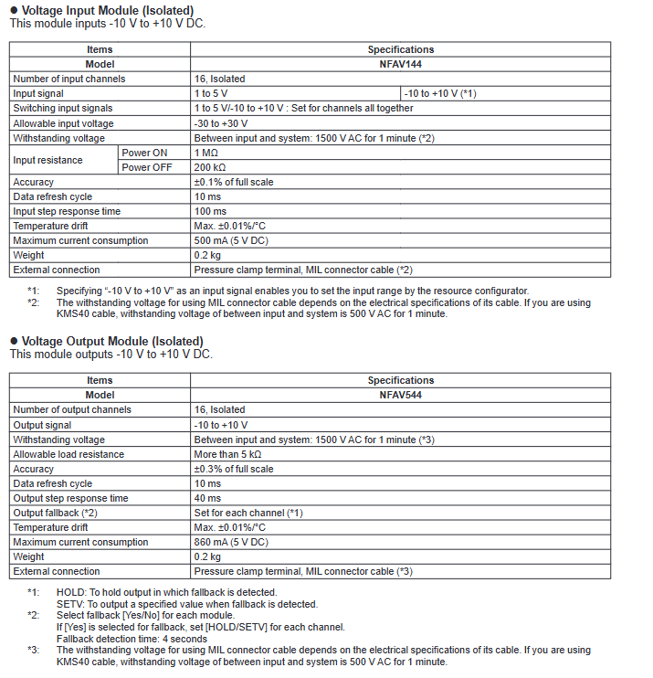
2. Voltage input/output module (isolated)
Model NFAV144 (voltage input) NFAV544 (voltage output)
Channel configuration: 16 channel input, isolated 16 channel output, isolated
I/O signal input: 1~5 V/-10~+10 V (uniformly set for all channels, -10~+10 V can be adjusted by the resource configurator) Output: -10~+10 V DC
Allowable Input/Load Allowable Input Voltage: -30~+30 V Allowable Load Resistance: ≥ 5 k Ω
Voltage resistance performance between input and system: 1500 V AC/1 minute (KMS40 cable: 500 V AC/1 minute) Output and system: 1500 V AC/1 minute (KMS40 cable: 500 V AC/1 minute)
Input/output resistance power on: 1 M Ω; power off: 200 k Ω No clear output resistance parameters
Core accuracy ± 0.1% full-scale ± 0.3% full-scale
Response performance data refresh cycle: 10 ms; Input step response time: 100 ms Data refresh cycle: 10 ms; Output step response time: 40 ms
Output Fallback without channel configuration (HOLD/SETV), detection time 4 seconds
Temperature drift maximum ± 0.01%/° C maximum ± 0.01%/° C
Power consumption 5 V DC: 500 mA; 24 V DC: No 5 V DC: 860 mA; 24 V DC: None
Weight 0.2 kg 0.2 kg
External connection pressure clamping terminal, MIL connector cable pressure clamping terminal, MIL connector cable
Special functions without HART communication; Wide range adaptation without HART communication; High load resistance requirement
3. TC/RTD input module (isolated)
Specially designed to receive thermocouple (TC), thermistor (RTD), or millivolt (mV) signals, suitable for temperature measurement scenarios, the core models are NFAT141 (TC/mV input) and NFAR181 (RTD input).
Model NFAT141 (TC/mV input) NFAR181 (RTD input)
Channel configuration: 16 channel input, isolated 12 channel input, isolated
Input signal TC: JIS C1602, IEC60584 standard Type J/K/E/B/R/S/T/N (Type B without temperature compensation, measured at ≥ 44 ℃); MV: -100~150 mV, -20~80 mV RTD: JIS C1604, IEC60751 standard Pt100 (three wire system), JIS C1604 standard JPt100 (three wire system)
Signal switching TC/mV can be set separately by channel (CH1~CH16) None
Allow input voltage ± 5 V ± 5 V
Voltage resistance performance between input and system: 1500 V AC/1 minute (MIL cable must meet corresponding voltage resistance requirements) Input and system: 1500 V AC/1 minute
Input resistance power on/off: ≥ 2 M Ω No clear parameters
Core precision TC input: ± 0.03% of full scale (-20~80 mV); MV input: ± 0.032% full range (-100~150 mV) ± 0.03% full range (0~400 Ω)
Allow total resistance signal source+wiring total resistance ≤ 1000 Ω, single wiring resistance ≤ 40 Ω, and each wire resistance is equal
Reference compensation accuracy ± 1 ℃ (affected by installation environment: ± 2 ℃ at -20~15 ℃/45~70 ℃; ± 1 ℃ at 15~45 ℃), coefficient K is required for temperatures below 0 ℃ (RTD does not require reference compensation)
Measuring current without 1 mA
Temperature drift TC input: maximum ± 30 ppm/° C; mV input: maximum ± 32 ppm/° C, maximum ± 30 ppm/° C
Data refresh cycle 1 second 1 second
The burn detection is uniformly set for all channels (enabled/disabled), with a detection time of 60 seconds
Power consumption 5 V DC: 450 mA; 24 V DC: No 5 V DC: 450 mA; 24 V DC: None
Weight 0.2 kg 0.2 kg
External connection pressure clamping terminal; Only mV input supports MIL connector cable pressure clamping terminal
Install restrictions to avoid radiation heat and direct airflow; Not adjacent to the CPU/power module; Can only be installed adjacent to designated modules (NFAT141/NFAR181/NFAV141/NFAV144) without special installation restrictions
4. Channel isolated current input/I/O module
The module not only has isolation between input/output and system, but also supports channel isolation, with stronger anti-interference ability. The core models are NFAI135 (current input) and NFAI835 (current I/O).
Model NFAI135 (current input) NFAI835 (current I/O)
Channel configuration: 8-channel input, channel isolation: 4-in/4-out, channel isolation
I/O signal input: 4~20 mA input: 4~20 mA; output: 4~20 mA
Allow input current of 25 mA
Overcurrent protection is equipped with
Voltage resistance performance between input and system, channel: 500 V AC/1 minute (MIL cable must meet voltage resistance requirements) Input/output and system, channel: 500 V AC/1 minute
Input resistance power on: 250 Ω (internal protection circuit may generate a maximum voltage drop of 0.8 V); Power off: ≥ 500 k Ω consistent with NFAI135
Allow no output of load resistance: 0~750 Ω
Wire breakage detection without output. Wire breakage detection threshold ≤ 0.65 mA
Core accuracy ± 0.1% full-scale input: ± 0.1% full-scale; Output: ± 0.3% full scale
Response performance data refresh cycle: 10 ms; input step response time: 100 ms Data refresh cycle: 10 ms; input/output step response time: 100 ms
Output Fallback without channel configuration (HOLD/SETV), detection time 4 seconds
The transmitter power supply is 20.2~29.3 V DC, which requires an external supply of 24 V DC
Temperature drift maximum ± 0.01%/° C maximum ± 0.01%/° C
Power consumption 5 V DC: 360 mA; 24 V DC:450 mA 5 V DC:360 mA; 24 V DC:450 mA
Weight 0.3 kg 0.3 kg
External connection pressure clamping terminal, MIL connector cable pressure clamping terminal, MIL connector cable
Special features support HART communication; Prohibit the connection of Zener barriers to support HART communication; Do not connect the Zener barrier
5. Pulse input module (isolated channel)
The model is NFAP135, which supports contact switching, voltage pulse, and current pulse inputs. The channels and systems are isolated, making it suitable for pulse counting scenarios.
Channel configuration: 8-channel input, channel isolation;
Input signal: 2-wire system (contact ON/OFF, voltage pulse, current pulse, can provide transmitter power), 3-wire system (power supply type voltage pulse);
Input frequency: 0~10 kHz (with changes in wiring capacitance during dry contact pulse input: 0~800 Hz at 1000 pF, 0~350 Hz at 10000 pF, 0~180 Hz at 30000 pF);
Minimum pulse width: 40 μ s (with capacitance variation: 625 μ s at 1000 pF, 1.43 ms at 10000 pF, 2.78 ms at 30000 pF when dry contact pulse input);
Signal level: Contact input (open circuit ≥ 100 k Ω, closed circuit ≤ 200 Ω); Voltage pulse (VH: 3-24 V, VL: -1~8 V, swing ≥ 3 V); Signal source resistance ≤ 1 k Ω;
Resistance configuration: shunt resistor (OFF/200/500/1000 Ω, open circuit when powered off); Pull up resistor (68 k Ω, 12/24 V DC);
Core function: Supports anti shake filtering (dry contact signals below 10 Hz); The transmitter power supply can be selected as 12/24 V DC (with a current limit of 40 mA for 12 V and 30 mA for 24 V);
Response performance: Data refresh cycle of 2 ms;
Power consumption: 5 V DC: 300 mA; 24 V DC:400 mA;
Weight: 0.3 kg;
External connections: pressure clamping terminals, MIL connector cables;
Installation restriction: When selecting a 500 Ω shunt resistor, no other modules can be installed next to the module, and a maximum of 4 input channels can be used;
Input modes: 5 modes (dry contact pulse/relay contact/voltage pulse/2-wire current pulse/3-wire voltage pulse), requiring corresponding configuration of power supply and shunt resistor.
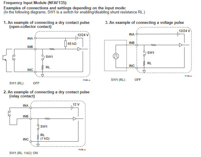
6. Frequency input module (isolated channel)
The model is NFAF135, used for measuring pulses and converting them into speed or frequency, with isolation between channels and systems.
Channel configuration: 8-channel input, channel isolation;
Input signal: Contact ON/OFF, voltage pulse (rectangular wave);
Input frequency: 0.1 Hz~10 kHz (varies with capacitance when dry contact pulse input: 0.1~800 Hz at 1000 pF, 0.1~350 Hz at 10000 pF, and 0.1~180 Hz at 30000 pF);
Frequency accuracy: 0.1% reading;
Signal level: consistent with NFAP135;
Resistance configuration: shunt resistor (OFF/1000 Ω, open circuit when powered off); Pull up resistor (68 k Ω, 12/24 V DC);
Core function: The on-site power supply can be selected as 12/24 V DC (with a current limit of 40 mA for 12 V and 30 mA for 24 V), and external 24 V DC is required;
Response performance: data refresh cycle of 10 ms;
Power consumption: 5 V DC: 300 mA; 24 V DC:400 mA;
Weight: 0.3 kg;
External connections: pressure clamping terminals, MIL connector cables;
Input mode: 3 modes (dry contact pulse/relay contact/voltage pulse), corresponding to the configuration of power supply and shunt resistor.
General technical characteristics and physical parameters
(1) General performance parameters
Accuracy level: Input modules are generally ± 0.1% full scale, output modules are mostly ± 0.3% full scale, and TC/RTD modules have higher accuracy (± 0.03%~± 0.032% full scale);
Temperature stability: Most modules have a temperature drift of ≤± 0.01%/° C or ± 30-32 ppm/° C, suitable for industrial environment temperature changes;
Power requirements: All modules require a 5 V DC system power supply, and some modules (such as current input/output modules) require an additional 24 V DC analog field power supply, which must be applied through the base module;
Voltage resistance and protection: The voltage resistance between the input/output of isolation modules and the system is mostly 1500 V AC/1 minute, while the voltage resistance between channels of channel isolation modules is 500 V AC/1 minute. The voltage resistance of MIL connector cables depends on the cable specifications (such as KMS40 cables with 500 V AC/1 minute);
Intrinsic safety requirements: All modules are prohibited from connecting to Zener barriers, and isolation barriers must be used in intrinsic safety application scenarios.
(2) Physical and Connection Parameters
Dimensions: All modules have a uniform size of 107.5 mm x 32.8 mm x 130 mm (length x width x height, unit: mm);
Weight: Most modules weigh 0.2~0.4 kg, with non isolated modules generally lighter (0.2 kg) and isolated output modules slightly heavier (such as NFAI543 which weighs 0.4 kg);
External connection: Unified use of pressure clamping terminals and MIL connector cables, some modules (such as NFAR181) only support pressure clamping terminals;
LED status indicator: All modules are equipped with 3 green LED indicator lights:
Status: Illuminates when hardware is normal;
ACT: Illuminates when executing input/output actions;
DX: Not used (permanently extinguished).
Model coding rules
The module model consists of "basic model+suffix code+option code", and the coding rules are as follows for easy selection and order confirmation:
(1) Basic model
The core functions and channel configurations of the representative module, such as NFAI141 (16 channel non isolated current input), NFAP135 (8-channel isolated pulse input), etc., have been explained in detail earlier.
(2) Suffix code
Used to distinguish the communication function, explosion-proof level, and special options of modules:
Example of applicable modules for suffix code function description
-S standard type (no special function) all models
-H supports HART communication NFAI141, NFAI841, etc
5. All models without explosion-proof protection
E with explosion-proof protection for all models
0 Basic type (no additional options) All models
1 with ISA Standard G3 option for all models
4 Wide Temperature Range Options (-40~+70 ℃) NFAP135, NFAR181
5 Wide Temperature Range+ISA Standard G3 Combination Options NFAP135, NFAR181
(3) Option code
Accessories such as terminal blocks and cable sheaths for specified modules:
Option code accessory description applicable module types
/13S00 with isolated analog/pulse/frequency dedicated pressure clamping terminal block (model: NFTI3S-00) current/pulse/frequency module
/13S10 isolation analog/pulse/frequency dedicated pressure clamping terminal block with surge absorber (model: NFTI3S-10) current/pulse/frequency module
/T4S00 thermocouple/mV dedicated pressure clamping terminal block (model: NFTT4S-00) NFAT141
/T4S10 Thermocouple/mV Special Pressure Clamp Terminal Block with Surge Absorber (Model: NFTT4S-10) NFAT141
/R8S00 RTD special pressure clamping terminal block (model: NFTR8S-00) NFAR181
/R8S10 RTD specific pressure clamping terminal block with surge absorber (model: NFTR8S-10) NFAR181
/A4S00 analog signal dedicated pressure clamping terminal block (model: NFTA4S-00) voltage input/output module
/A4S10 Analog Signal Special Pressure Clamp Terminal Block with Surge Absorber (Model: NFTA4S-10) Voltage Input/Output Module
/CCC01 MIL cable connector sheath (model: NFCCC01) All modules that support MIL cables
Installation restrictions and precautions
(1) Special module installation restrictions
NFAT141 (TC input module):
Avoid radiation heat effects: Do not install heating units below and do not expose them to direct airflow;
Module layout: Cannot be adjacent to CPU modules (NFCP501/NFCP502) or power modules (NFPW44x);
Adjacent module restriction: It can only be installed adjacent to NFAT141, NFAR181, NFAV141, and NFAV144, and at least one empty slot must be reserved for other modules.
NFAP135 (Pulse Input Module):
Partial current resistor limitation: When selecting a 500 Ω partial current resistor, no other modules can be installed on both sides of the module, and a maximum of 4 input channels can be used.
(2) General installation requirements
Power capacity matching: When installing modules, it is necessary to ensure that the total power consumption does not exceed the rated output of the power module, with a focus on:
5 V DC system power supply: current consumption of NFAV544, NFDV551, NFDV561, NFDR541;
24 V DC simulated on-site power supply: NFAI841, NFAI143, NFAI543 current consumption.
Explosion proof selection: Modules with the suffix "E" must be selected for explosion-proof scenarios, and the compliance of the selection must be confirmed by referring to the STARDOM FCN/FCJ Installation Guide.
Wiring and Connection:
Follow the requirements of the "On site Connection Specification" (GS 34P02Q30-01E) to ensure that the wiring is firm and the shielding is good;
The voltage resistance of MIL connector cables must meet the requirements of the module to avoid insufficient voltage resistance caused by improper cable selection.
- YOKOGAWA
- Reliance
- ADVANCED
- SEW
- ProSoft
- WATLOW
- Kongsberg
- FANUC
- VSD
- DCS
- PLC
- man-machine
- Covid-19
- Energy and Gender
- Energy Access
- Renewable Integration
- Energy Subsidies
- Energy and Water
- Net zero emission
- Energy Security
- Critical Minerals
- A-B
- petroleum
- Mine scale
- Sewage treatment
- cement
- architecture
- Industrial information
- New energy
- Automobile market
- electricity
- Construction site
- HIMA
- ABB
- Rockwell
- Schneider Modicon
- Siemens
- xYCOM
- Yaskawa
- Woodward
- BOSCH Rexroth
- MOOG
- General Electric
- American NI
- Rolls-Royce
- CTI
- Honeywell
- EMERSON
- MAN
- GE
- TRICONEX
- Control Wave
- ALSTOM
- AMAT
- STUDER
- KONGSBERG
- MOTOROLA
- DANAHER MOTION
- Bentley
- Galil
- EATON
- MOLEX
- Triconex
- DEIF
- B&W
- ZYGO
- Aerotech
- DANFOSS
- KOLLMORGEN
- Beijer
- Endress+Hauser
- schneider
- Foxboro
- KB
- REXROTH
- YAMAHA
- Johnson
- Westinghouse
- WAGO
- TOSHIBA
- TEKTRONIX
- BENDER
- BMCM
- SMC
- HITACHI
- HIRSCHMANN
- XP POWER
- Baldor
- Meggitt
- SHINKAWA
- Other Brands
- UniOP
- KUKA
- IBA
- Beckhoff
- ADLINK
-
ADLINK HPCI-14S12U - Industrial Control Backplane 12PCI Backplane PCI-14S Passive Backplane
-
ADLINK PCIe-GIE74C - image acquisition card 4-CH GigE Vision PoE+ Frame Grabber
-
ADLINK PCI-8164 - control card 4-Axis Advanced Motion Controller Board
-
ADLINK PCIe-U304 - 4 Port USB3 PCIe Frame Grabbers USB Screw Hole Card
-
ADLINK PCI-9112 - Multi-Function Data Acquisition Card DAQ Card
-
ADLINK PCI-7432 - 51-12013-0A50 4-CH Isolated Numérique I/O PCI Cartes Digital I/O Card
-
ADLINK PCA-6106P3-0C1 REV.C1 - backplane 6-Slot Passive Backplane Board
-
ADLINK PCI-7224 - 24-CH Opto-Isolated Digital I/O PCI Board
-
ADLINK CPCI-7433R(G) - Digital Input Board Rear I/O CompactPCI Card
-
ADLINK EBP-13E4 - 51-46703-0A30 Industrial PC Backplane Passive Backplane
-
ADLINK PCIE-HDV62 - Image acquisition card High Definition Video Frame Grabber
-
ADLINK EBP-13E4 - 51-46703-0A30 Industrial Backplane Board Passive Backplane
-
ADLINK 90111-B1 / CPCI-6770 - PCB CPU MODULE CompactPCI Single Board Computer
-
ADLINK PCI-7248 - DATA ACQUISITION PCI CARD 48-CH Parallel Digital I/O Board
-
ADLINK PCI-7230 - 51-12003-0a50 board PCI7230 32-CH Isolated Digital I/O Card
-
ADLINK PCI2A000CB - 51-20000-0B30 Multi-Function DAQ Card Baseboard
-
ADLINK PCI-8134-005 - 4-Axis Motion Controller Card
-
ADLINK PCI-7224 - 24-CH Opto-Isolated Digital I/O PCI Card
-
ADLINK PCI-7434 - 64-CH Isolated Digital Output Card
-
ADLINK PCI-8132 - motion control card 2-Axis Servo & Stepper Controller
-
ADLINK PCI-8134 - Motion Controller PCI Card 4-Axis Controller Board
-
ADLINK PCI-8164 - Motion Control Card 51-12406-0A40 4-Axis Controller
-
ADLINK 51-12001-0C20 - Circuit Board Data Acquisition Interface Module Hardware
-
ADLINK NuPR0-840 - industrial control motherboard Full-Size PICMG CPU Board
-
ADLINK PCI-7444 - 51-12023-0A10 card 128-CH Isolated Digital Output Board
-
ADLINK PCI-1612B - data acquisition card 4-Port RS-232/422/485 Serial Communication Card
-
ADLINK PCI-6208V 009 - 8/16-CH 16-Bit Analog Output Cards PCB-I-E-482=6BX3
-
ADLINK NUPRO-935A/LV - industrial control motherboard Full-Size PICMG SBC Board
-
ADLINK PCI-9114DG - Multi-Function DAQ Card Data Acquisition PCI Card
-
ADLINK ACL-7130 - Data acquisition card Isolated Digital I/O Board
-
ADLINK ABX-6300D-4E1-BP - board ABX6300D4E1BP Video Interface Expansion Card
-
ADLINK CPCI-6940 - CPCI-6940/D1539/M16-0(EA)-000E 6U CompactPCI Processor Board
-
ADLINK NuPRO-760 - industrial control motherboard Half-Size PICMG SBC CPU Board
-
ADLINK IMB-M42H (G)-0020 - industrial control motherboard LGA1155 Micro-ATX Mainboard
-
ADLINK RTV-24 / PCI-MP4S - 51-12519-1C30 4-Channel Real Time Video Capture Board
-
ADLINK PCI-8134 - 4-Axis Servo & Stepper Motion Controller Card
-
ADLINK MXC-6101D - V.PC000.002.ST.00 Box PC Configurable Embedded Computer
-
ADLINK PCI-8134A - 51-12421-0A10 Motion Control Card 4-Axis Controller Card
-
ADLINK DIN-100S / DIN-100SA1 - Technology SCSI-II TB 100-PIN Terminal Block Board
-
ADLINK DIN-812M001 / DIN812M001 - 51-14034-0A1 51140340A1 Terminal Module Breakout Interface
-
ADLINK PCI-8164 - Servo motion control 4-Axis Advanced Controller Card
-
ADLINK PCIe-GIE64 - Acquisition card GigE Vision PoE+ Frame Grabber
-
ADLINK M-302 - Industrial control motherboard ATX PC Board Mainboard
-
ADLINK PCI-8134 - Motion Controller PCI Card 4-Axis Controller Board
-
ADLINK PCI-RTV24 - Image capture card Analog Video Frame Grabber
-
ADLINK PCI-8102 - Motion control card 2-Axis Servo & Stepper Controller Board
-
ADLINK PCI-9112 REV.B1 - Card Multi-Function Data Acquisition Card
-
ADLINK HSI-DI32-M-N / HSL-TB32-M-DIN - Discrete I/O MODULE Distributed Automation Module System
-
ADLINK PCI-7296 - IO card REV.A3 96-CH Parallel Digital I/O Card
-
ADLINK DIN-814P-A4 / 814Y - terminal board Motion Control Interface Block
-
ADLINK DIN-814P-A4 - 51-14056-0A10 PCB-I-E-2736=ZA01 Screw Terminal Board Breakout
-
ADLINK M-322 - motherboard Industrial Control Computer Mainboard
-
ADLINK NUPRO-406 REV:B1 - industrial control motherboard Full-Size PICMG CPU Board
-
ADLINK AMP-204C - card DSP-Based 4-Axis Advanced Pulse-Train Controller
-
ADLINK HPCI14S REV.B1 - industrial computer baseboard 14-Slot Passive Backplane
-
ADLINK PCI-7250 - 8-CH Relay Output & 8-CH Isolated DI PCI Card
-
ADLINK EBP-13E2 - baseplate Passive Backplane Industrial Computer Chassis Board
-
ADLINK LPCI-3488A - PCI-GPIB card 51-12801-0A30 acquisition card IEEE-488 Interface Board
-
ADLINK PCI-6216V-GL - 51-12201-0C30 16-CH 16-Bit Voltage Analog Output Card
-
ADLINK ACL-8454 - 16-CH Isolated Digital I/O & 4-CH Counter Card
-
ADLINK HPCI-9S7U - backplane Passive Backplane Compatible with NuPRO-A301 852 841 842
-
ADLINK DAQ-2010-007 - Simultaneous-Sampling Multi-Function Data Acquisition Card
-
ADLINK MP-C154 - 51-64205-0A10 Motion Control Card 4-Axis Controller Board
-
ADLINK MXE-202/mSSD16B/WiFi-BT - Matrix Rugged I/O Platform Embedded Fanless Computer
-
ADLINK CM-920-R-17 - PC/104-Plus Single Board Computer Module Intel Celeron M
-
ADLINK PCI-7250 NSMP - 8-CH Relay Output & 8-CH Isolated DI Card
-
ADLINK PCI-8164 - 4-Axis Motion Controller PCI Card W/ Cable and Breakout Box
-
ADLINK EMX-100 - Ethernet-based 4-axis Motion Controllers Distributed Motion Module
-
ADLINK PCI-8134A - Press control card 4-Axis Motion Controller Board
-
ADLINK M-845EG REV:3.2 - industrial motherboard Pentium 4 Socket 478 Micro-ATX
-
ADLINK PCI-9114A Rev A2 DG - card High-Resolution Multi-Function Data Acquisition Board
-
ADLINK IEC-915GV - REV 1.1 Industrial motherboard Socket 478 CPU Board
-
ADLINK PCI-9111DG(G) - Data Acquisition Card Multi-Function DAQ Card
-
ADLINK HPCI-15S10 REV:B2 - Industrial computer base plate Passive Backplane Board
-
ADLINK NuPR0-840 / NuPR0-840DV - industrial control motherboard Full-size PICMG CPU Board
-
ADLINK RTV-24 / PCI-MP4S - 51-12519-1C30 4-Channel Real Time Video Capture Board
-
ADLINK NUPRO-780 - industrial control motherboard Pentium III Single Board Computer
-
ADLINK PCI-7296 - 0050 card 96-CH Opto-Isolated Parallel DIO Card Set
-
ADLINK NUPRO-780 - industrial control motherboard PICMG Full-Size SBC
-
ADLINK PCI-7248 - 51-12006-0A3 002 Pci 7248 48-CH Parallel Digital I/O Card
-
ADLINK cPCI-6626 - 6U CompactPCI 2.0 Blades i7-2710QE PCB-I-E-2570=9N41
-
ADLINK MXC-6322D(G) - Industrial Fanless Computer
-
ADLINK cPCI-8168-004 - CompactPci NulPC Motion Control Board 51-36402-0A3
-
ADLINK CPCI-7300[G] - COMPACTPCI Digital I/O Card Data Acquisition
-
ADLINK CPCI-6626/2710/M4G - COMPACTPCI COMPUTER BOARD
-
ADLINK cPCI-8168-009 - cPCI NulPC Motion Control Board
-
ADLINK cPCI-6626/2710/M4G - VME CPU Board Computer Board
-
ADLINK CPCI-R6200(G)-0040 - COMPACTPCI CONTROL BOARD
-
ADLINK CPCI-3840/PM18/M1G(G)-3650 - COMPACTPCI CPU Module Single Board Computer
-
ADLINK cPCI-7248 - 48-CH Opto-22 Compatible Digital I/O Module
-
ADLINK DLAP-211-JNX - NVIDIA Jetson Xavier NX Edge AI Inference Platform
-
ADLINK cPCI-3544 - Series 4-Port RS-422/485 Isolated Serial Communications Card
-
ADLINK CM1-86DX3 - PC/104 SBC Stanley Vortex86DX3 CPU 2GB Ram
-
ADLINK DLAP-211-JNX - NVIDIA Jetson Xavier NX Edge AI Inference Platform
-
ADLINK cPCI-3544 - Series 4-Port RS-422/485 Isolated Serial Communications Card
-
ADLINK CM1-86DX3 - PC/104 SBC Stanley Vortex86DX3 CPU 2GB Ram
-
ADLINK PCI-7433 - switch value acquisition card Isolated Digital Input Card
-
ADLINK PCI-9112 - 51-12252-0D20 Multi-Function Data Acquisition Card
-
ADLINK NUPRO-A301 REV:1.4 - industrial control motherboard PICMG Full-Size SBC
-
ADLINK 51-18502-0A10 - Frame Grabber Image Acquisition Interface Card
-
ADLINK PCI-7296 - 51-12009-0A50 PCB-I-E-925=6DX1 96-CH Parallel Digital I/O Board
-
ADLINK PCI-8132 GP A2 - Motion Control Card 2-Axis Servo & Stepper Controller
-
ADLINK PCI-7442 - switch quantity card data acquisition card 64-CH Isolated Card
-
ADLINK HPX-13S4 - baseboard PICMG 1.3 Passive Backplane Chassis Baseplate
-
ADLINK NuPRO-590 / NTC-567-ZM-F36 - Single Board Computer PCB-I-E-1853=9L21 Half-Size SBC
-
ADLINK PCIe-8332 - 16-axis plate Motion Control Hardware Card
-
ADLINK NuPRO-775 REV.B1 - motherboard Pentium 4 Full-Size PICMG SBC
-
ADLINK PXI-3920 - Embedded Controller 3U PXI cPCI System Intelligence Board
-
ADLINK PCI-8134 - driver card motion control card 4-Axis Controller Board
-
ADLINK HSL-DI32-M-N-011 / HSL-TB32-M-DIN - Digital Input & Base Module PLC Distributed I/O System
-
ADLINK PCI-6216V-206 / PCI-208V 009 - 16 CH 16bit analog output card
-
ADLINK NuPro-E330 - 51-41805-0A20 PCB Single Board Computer Host Board
-
ADLINK PCI-1622C - Card 8-Port RS-232/422/485 PCI Serial Communication Board
-
ADLINK PCIe-7432 - 51-18402-0A10 Carte PCIe Avec Plage D'Entrée Élevée Isolated DIO Card
-
ADLINK PCI-7250 - PCI Acquisition Card 8-CH Relay Output Isolated DI Card
-
ADLINK PCI-7230 - 32-CH Isolated Digital I/O Card
-
ADLINK PCI-8164 - PCB 4-Axis Motion Controller Card
-
ADLINK PCI-7854 - Collection card High-Speed Link Distributed Motion Controller
-
ADLINK NuPRO-935A/LV - industrial control computer motherboard Full-Size PICMG SBC
-
ADLINK IMB-M40H - motherboard IH61-AA4 1155 LGA1155 Micro-ATX Mainboard
-
ADLINK PCI-7248 - Linhua 51-12006-0A40 48-CH Parallel Digital I/O Card
-
ADLINK HPCI-14S12U - Linhua industrial computer baseboard Passive Backplane
-
ADLINK PCI-8132 Rev.A2 - 2-Axis Servo & Stepper Motion Controller Card
-
ADLINK ACL-8111 - ISA card Multi-Function DAQ Card
-
ADLINK ACL-8111 - ISA card Multi-Function Data Acquisition Board
-
ADLINK PCI-7200 REV.A3 - Digital I/O card 12MB/s High-Speed Parallel Digital I/O
-
ADLINK PCI-7296 REV.A3 - 96-CH High-Density Opto-Isolated DIO Card
-
ADLINK PCI-7434 - 64-CH Isolated Digital Output Card

K-JIANG

Add: Jimei North Road, Jimei District, Xiamen, Fujian, China
Tell:+86-15305925923