
K-WANG


YOKOGAWA AFV40S/AFV40D on-site control unit (with cabinet)
YOKOGAWA AFV40S/AFV40D on-site control unit (with cabinet)
Core hardware configuration and specifications
1. Core module configuration
Module Type Single Redundancy (AFV40S) Double Redundancy (AFV40D) Key Description
1 power module (PW481/PW482/PW484), 2 optional dual power supplies (redundant configuration) supporting 100-120V AC/220-240V AC/24V DC
1 processor module (CP461/CP471) 2 (redundant of the same model) CP471 needs to be equipped with R6.05 or above control functions
1 ESB bus coupling module (EC401/EC402), optional dual redundancy 2 (EC401/EC402, mandatory dual redundancy) EC401 can connect up to 9 nodes, EC402 can connect up to 11 nodes
Up to 6 I/O modules (non-standard configuration) must comply with the FIO system installation restrictions
2. Built in components of the cabinet
Basic components: 1 FCU, 1 power distribution board with HKU, 2 vertical power bus units (1 front and 1 rear)
Cooling components: 4 door fans (2 for each front and rear door), node fans (ANFAN, configured according to the number of units)
Monitoring component: HKU (House Keeping Unit), standard configuration, supports cabinet environment monitoring
3. Communication interface specifications
Core characteristics of interface type redundancy configuration
Vnet/IP interface dual redundancy (AFV40S selectable power supply, AFV40D forced dual power supply) system control network, redundant switching ensures stable communication
ESB bus interface AFV40S: single/dual redundancy; AFV40D: Mandatory dual redundant connection node unit, EC401 supports bus topology, EC402 supports upper and lower connection nodes
The HK bus interface is connected to the external cabinet HKU via a single channel, with AKBHKU cable and a total length of ≤ 100m
READY contact output 3 terminal (NC/NO/C) fault, contact on/off, rated 250V AC/30V DC, maximum 2A/125VA
Key parameters and physical characteristics
1. Electrical parameters
Parameter specifications
Power supply voltage 100-120V AC (50/60Hz), 220-240V AC (50/60Hz), 24V DC
Maximum power consumption 100-120V AC: 2500VA; 220-240V AC:2860VA; 24V DC:71A
Power down protection: Main memory battery backup takes up to 72 hours and charging takes at least 48 hours
Protection level IP20
2. Physical characteristics
Parameter specifications
External dimensions (mm) Height 2105 x Width 800 x Depth 600 (including 25mm front and rear protrusions)
Weight approximately 240kg (excluding nodes); About 360kg (fully equipped with 11 nodes)
Paint color subject: Frost white (Munsell 2.5Y 8.4/1.2); Channel Base: Spring Black (Munsell 3.3PB2.5/0.5)
Grounding terminal M8 screw terminal connection
Power connection M6 screw terminal connection, supports dual power supply system
Installation restrictions and connection capabilities
1. Node unit connection restrictions
Limit type specifications
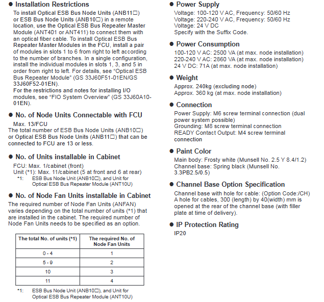
Maximum number of connected nodes 13/FCU (ANB10 /ANB11 )
The maximum number of installed units in the cabinet is 11 (ANB10 node unit+ANT10U optical ESB relay unit)
There are a maximum of 5 installation positions in the front and 6 installation positions in the rear of the cabinet
Installation sequence: Install the ANB10 node unit first, and then install the ANT10U relay unit
The optical ESB node connection requires the use of ANT401/ANT411 optical relay modules, with a maximum transmission distance of 50km
2. Fan configuration rules
Number of required node fans (ANFAN) for the total number of units in the cabinet (ANB10 +ANT10U)
0-4 of 1 (option code/1-FAN)
5-9 of 2 (Option Code/2-FAN)
10 of 3 (option code/3-FAN)
11 of 4 (option code/4-FAN)
3. Cable and topology limitations
ESB bus cable: Use YCB301 dedicated cable, pre installed in the cabinet, additional connection is required between ANB10 and ANT10U
HK bus: AKBHKU cable is used to connect external cabinets, with a total length of ≤ 100m (daisy chain connection)
Optical ESB bus: supports chain/star topology and requires the use of ANT401/ANT411 relay modules
Model code and options
1. Basic model and core suffix
Product Model Core Suffix Description Key Configuration
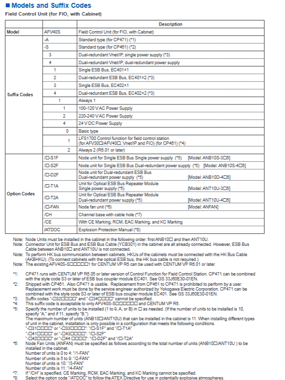
AFV40S (single redundancy) - A/- S (processor type); 3/4 (Vnet/IP and power supply); 1-4 (ESB bus); 1/2/4 (power type) selectable/dual redundant ESB bus, single/dual power supply
AFV40D (dual redundancy) - A/- S (processor type); 4 (Vnet/IP and power supply); 2/4 (ESB bus); 1/2 (power type) mandatory dual redundancy Vnet/IP and ESB bus
2. Main option codes
Option code function description associated model
/ - S1F single ESB bus+single power node unit ANB10S-3 5
/- D2F dual redundant ESB bus+dual power node unit ANB10D-4 5
/ - T2A dual power optical ESB relay unit ANT10U-4 5
/ - FAN node fans (configured by quantity) ANFAN
/CH Channel Base with Cable Hole (300 × 40mm)-
/CE with CE/RCM/AAC/KC certification-
/ATDOC Explosion proof Manual (ATEX Directive Adaptation)-
Software and accessory requirements
Software requirements: A separate software license is required. We recommend VP6F1700 control function software and VP6F3100 Project I/O license
SEM functional requirements: The use of event sequence manager requires specific hardware conditions, refer to GS 33J30D10-01EN
Standard accessories: 2 door fan filters (Part No.T9070CB)
Related products: Cabinet Connection Kit (Model AKT211), Cabinet Side Panel (ACB2P, requires paired configuration)
Key issues
Question 1: What is the core difference between AFV40S and AFV40D? How to select based on project redundancy requirements?
answer
Core Differences:
Redundancy configuration: AFV40S is single redundancy (optional dual redundancy for processor/power/ESB bus), AFV40D is full dual redundancy (mandatory dual redundancy for processor/power/Vnet/IP/ESB bus);
Suffix restrictions: AFV40D only supports dual redundancy related suffixes (such as ESB bus with only 2/4 options), while AFV40S supports single/dual redundancy suffixes;
Node Unit: AFV40S supports single/dual power node units, while AFV40D only supports dual redundant ESB+dual power node units (ANB10D-4 5).
Selection principle:
High reliability requirements (such as critical process control): Choose AFV40D, fully redundant configuration to avoid single point of failure;
Cost sensitive and non critical scenarios: Choose AFV40S and configure single/dual redundant ESB buses and power supplies as needed;
Number of nodes ≤ 9: AFV40S with EC401; Number of nodes 10-11: AFV40S with EC402, AFV40D with EC402.
Question 2: What are the key rules for unit installation and fan configuration in the AFV40 cabinet? How to avoid installation violations?
answer
Unit installation rules:
Quantity limit: A maximum of 11 units (ANB10 +ANT10U) can be installed in the cabinet, with ≤ 5 units in the front and ≤ 6 units in the rear;
Installation sequence: ANB10 node unit must be installed first, followed by ANT10U optical relay unit;
Cable connection: The ESB bus cable (YCB301) inside the cabinet has been pre installed, and manual connection is required between ANB10 and ANT10U.
Fan configuration rules:
The number of node fans (ANFAN) is configured according to the total number of units (0-4 → 1, 5-9 → 2, 10 → 3, 11 → 4);
Door fans are standard configuration (4 units), no additional selection is required.
Avoid violations:
Install strictly in the order of "ANB10 priority", without reversing unit types;
Accurately select fan option codes based on the total number of units, without omission or excessive configuration;
The optical ESB node needs to be connected through the ANT401/ANT411 relay module, not directly connected to the FCU.
Question 3: What are the communication interface and power configuration options for AFV40? How to adapt to different on-site power supply conditions?
answer
Communication interface selection:
Vnet/IP interface: dual redundant configuration (AFV40S can provide a single power supply, AFV40D requires dual power supply), used for system control network;
ESB bus interface: AFV40S can be selected as a single menu (EC401/EC402 × 1) or dual redundancy (EC401/EC402 × 2), AFV40D is mandatory dual redundancy, used to connect node units;
HK bus interface: single channel, used to connect external cabinet HKU, total length ≤ 100m.
Power configuration selection:
Power supply type: Supports 100-120V AC (50/60Hz), 220-240V AC (50/60Hz), 24V DC, specified by suffix code;
Power redundancy: AFV40S can provide single/dual power supply, while AFV40D requires dual power supply.
On site adaptation plan:
Conventional industrial power supply (220-240V AC): choose suffix "2", AFV40S can be a single power supply (suffix "3") or a dual power supply (suffix "4");
Low voltage scenario (24V DC): Select suffix "4" and confirm that the on-site DC power supply capacity is ≥ 71A;
Cross border project: Select option code "/CE" to obtain CE/RCM/ECC/KC multi certification adaptation;
Explosion proof scenario: Select option code "/ATDOC" to obtain the ATEX Directive Adaptation Manual.
- YOKOGAWA
- Reliance
- ADVANCED
- SEW
- ProSoft
- WATLOW
- Kongsberg
- FANUC
- VSD
- DCS
- PLC
- man-machine
- Covid-19
- Energy and Gender
- Energy Access
- Renewable Integration
- Energy Subsidies
- Energy and Water
- Net zero emission
- Energy Security
- Critical Minerals
- A-B
- petroleum
- Mine scale
- Sewage treatment
- cement
- architecture
- Industrial information
- New energy
- Automobile market
- electricity
- Construction site
- HIMA
- ABB
- Rockwell
- Schneider Modicon
- Siemens
- xYCOM
- Yaskawa
- Woodward
- BOSCH Rexroth
- MOOG
- General Electric
- American NI
- Rolls-Royce
- CTI
- Honeywell
- EMERSON
- MAN
- GE
- TRICONEX
- Control Wave
- ALSTOM
- AMAT
- STUDER
- KONGSBERG
- MOTOROLA
- DANAHER MOTION
- Bentley
- Galil
- EATON
- MOLEX
- Triconex
- DEIF
- B&W
- ZYGO
- Aerotech
- DANFOSS
- KOLLMORGEN
- Beijer
- Endress+Hauser
- schneider
- Foxboro
- KB
- REXROTH
- YAMAHA
- Johnson
- Westinghouse
- WAGO
- TOSHIBA
- TEKTRONIX
- BENDER
- BMCM
- SMC
- HITACHI
- HIRSCHMANN
- XP POWER
- Baldor
- Meggitt
- SHINKAWA
- Other Brands
- UniOP
- KUKA
- IBA
- Beckhoff
- ADLINK
-
ADLINK HPCI-14S12U - Industrial Control Backplane 12PCI Backplane PCI-14S Passive Backplane
-
ADLINK PCIe-GIE74C - image acquisition card 4-CH GigE Vision PoE+ Frame Grabber
-
ADLINK PCI-8164 - control card 4-Axis Advanced Motion Controller Board
-
ADLINK PCIe-U304 - 4 Port USB3 PCIe Frame Grabbers USB Screw Hole Card
-
ADLINK PCI-9112 - Multi-Function Data Acquisition Card DAQ Card
-
ADLINK PCI-7432 - 51-12013-0A50 4-CH Isolated Numérique I/O PCI Cartes Digital I/O Card
-
ADLINK PCA-6106P3-0C1 REV.C1 - backplane 6-Slot Passive Backplane Board
-
ADLINK PCI-7224 - 24-CH Opto-Isolated Digital I/O PCI Board
-
ADLINK CPCI-7433R(G) - Digital Input Board Rear I/O CompactPCI Card
-
ADLINK EBP-13E4 - 51-46703-0A30 Industrial PC Backplane Passive Backplane
-
ADLINK PCIE-HDV62 - Image acquisition card High Definition Video Frame Grabber
-
ADLINK EBP-13E4 - 51-46703-0A30 Industrial Backplane Board Passive Backplane
-
ADLINK 90111-B1 / CPCI-6770 - PCB CPU MODULE CompactPCI Single Board Computer
-
ADLINK PCI-7248 - DATA ACQUISITION PCI CARD 48-CH Parallel Digital I/O Board
-
ADLINK PCI-7230 - 51-12003-0a50 board PCI7230 32-CH Isolated Digital I/O Card
-
ADLINK PCI2A000CB - 51-20000-0B30 Multi-Function DAQ Card Baseboard
-
ADLINK PCI-8134-005 - 4-Axis Motion Controller Card
-
ADLINK PCI-7224 - 24-CH Opto-Isolated Digital I/O PCI Card
-
ADLINK PCI-7434 - 64-CH Isolated Digital Output Card
-
ADLINK PCI-8132 - motion control card 2-Axis Servo & Stepper Controller
-
ADLINK PCI-8134 - Motion Controller PCI Card 4-Axis Controller Board
-
ADLINK PCI-8164 - Motion Control Card 51-12406-0A40 4-Axis Controller
-
ADLINK 51-12001-0C20 - Circuit Board Data Acquisition Interface Module Hardware
-
ADLINK NuPR0-840 - industrial control motherboard Full-Size PICMG CPU Board
-
ADLINK PCI-7444 - 51-12023-0A10 card 128-CH Isolated Digital Output Board
-
ADLINK PCI-1612B - data acquisition card 4-Port RS-232/422/485 Serial Communication Card
-
ADLINK PCI-6208V 009 - 8/16-CH 16-Bit Analog Output Cards PCB-I-E-482=6BX3
-
ADLINK NUPRO-935A/LV - industrial control motherboard Full-Size PICMG SBC Board
-
ADLINK PCI-9114DG - Multi-Function DAQ Card Data Acquisition PCI Card
-
ADLINK ACL-7130 - Data acquisition card Isolated Digital I/O Board
-
ADLINK ABX-6300D-4E1-BP - board ABX6300D4E1BP Video Interface Expansion Card
-
ADLINK CPCI-6940 - CPCI-6940/D1539/M16-0(EA)-000E 6U CompactPCI Processor Board
-
ADLINK NuPRO-760 - industrial control motherboard Half-Size PICMG SBC CPU Board
-
ADLINK IMB-M42H (G)-0020 - industrial control motherboard LGA1155 Micro-ATX Mainboard
-
ADLINK RTV-24 / PCI-MP4S - 51-12519-1C30 4-Channel Real Time Video Capture Board
-
ADLINK PCI-8134 - 4-Axis Servo & Stepper Motion Controller Card
-
ADLINK MXC-6101D - V.PC000.002.ST.00 Box PC Configurable Embedded Computer
-
ADLINK PCI-8134A - 51-12421-0A10 Motion Control Card 4-Axis Controller Card
-
ADLINK DIN-100S / DIN-100SA1 - Technology SCSI-II TB 100-PIN Terminal Block Board
-
ADLINK DIN-812M001 / DIN812M001 - 51-14034-0A1 51140340A1 Terminal Module Breakout Interface
-
ADLINK PCI-8164 - Servo motion control 4-Axis Advanced Controller Card
-
ADLINK PCIe-GIE64 - Acquisition card GigE Vision PoE+ Frame Grabber
-
ADLINK M-302 - Industrial control motherboard ATX PC Board Mainboard
-
ADLINK PCI-8134 - Motion Controller PCI Card 4-Axis Controller Board
-
ADLINK PCI-RTV24 - Image capture card Analog Video Frame Grabber
-
ADLINK PCI-8102 - Motion control card 2-Axis Servo & Stepper Controller Board
-
ADLINK PCI-9112 REV.B1 - Card Multi-Function Data Acquisition Card
-
ADLINK HSI-DI32-M-N / HSL-TB32-M-DIN - Discrete I/O MODULE Distributed Automation Module System
-
ADLINK PCI-7296 - IO card REV.A3 96-CH Parallel Digital I/O Card
-
ADLINK DIN-814P-A4 / 814Y - terminal board Motion Control Interface Block
-
ADLINK DIN-814P-A4 - 51-14056-0A10 PCB-I-E-2736=ZA01 Screw Terminal Board Breakout
-
ADLINK M-322 - motherboard Industrial Control Computer Mainboard
-
ADLINK NUPRO-406 REV:B1 - industrial control motherboard Full-Size PICMG CPU Board
-
ADLINK AMP-204C - card DSP-Based 4-Axis Advanced Pulse-Train Controller
-
ADLINK HPCI14S REV.B1 - industrial computer baseboard 14-Slot Passive Backplane
-
ADLINK PCI-7250 - 8-CH Relay Output & 8-CH Isolated DI PCI Card
-
ADLINK EBP-13E2 - baseplate Passive Backplane Industrial Computer Chassis Board
-
ADLINK LPCI-3488A - PCI-GPIB card 51-12801-0A30 acquisition card IEEE-488 Interface Board
-
ADLINK PCI-6216V-GL - 51-12201-0C30 16-CH 16-Bit Voltage Analog Output Card
-
ADLINK ACL-8454 - 16-CH Isolated Digital I/O & 4-CH Counter Card
-
ADLINK HPCI-9S7U - backplane Passive Backplane Compatible with NuPRO-A301 852 841 842
-
ADLINK DAQ-2010-007 - Simultaneous-Sampling Multi-Function Data Acquisition Card
-
ADLINK MP-C154 - 51-64205-0A10 Motion Control Card 4-Axis Controller Board
-
ADLINK MXE-202/mSSD16B/WiFi-BT - Matrix Rugged I/O Platform Embedded Fanless Computer
-
ADLINK CM-920-R-17 - PC/104-Plus Single Board Computer Module Intel Celeron M
-
ADLINK PCI-7250 NSMP - 8-CH Relay Output & 8-CH Isolated DI Card
-
ADLINK PCI-8164 - 4-Axis Motion Controller PCI Card W/ Cable and Breakout Box
-
ADLINK EMX-100 - Ethernet-based 4-axis Motion Controllers Distributed Motion Module
-
ADLINK PCI-8134A - Press control card 4-Axis Motion Controller Board
-
ADLINK M-845EG REV:3.2 - industrial motherboard Pentium 4 Socket 478 Micro-ATX
-
ADLINK PCI-9114A Rev A2 DG - card High-Resolution Multi-Function Data Acquisition Board
-
ADLINK IEC-915GV - REV 1.1 Industrial motherboard Socket 478 CPU Board
-
ADLINK PCI-9111DG(G) - Data Acquisition Card Multi-Function DAQ Card
-
ADLINK HPCI-15S10 REV:B2 - Industrial computer base plate Passive Backplane Board
-
ADLINK NuPR0-840 / NuPR0-840DV - industrial control motherboard Full-size PICMG CPU Board
-
ADLINK RTV-24 / PCI-MP4S - 51-12519-1C30 4-Channel Real Time Video Capture Board
-
ADLINK NUPRO-780 - industrial control motherboard Pentium III Single Board Computer
-
ADLINK PCI-7296 - 0050 card 96-CH Opto-Isolated Parallel DIO Card Set
-
ADLINK NUPRO-780 - industrial control motherboard PICMG Full-Size SBC
-
ADLINK PCI-7248 - 51-12006-0A3 002 Pci 7248 48-CH Parallel Digital I/O Card
-
ADLINK cPCI-6626 - 6U CompactPCI 2.0 Blades i7-2710QE PCB-I-E-2570=9N41
-
ADLINK MXC-6322D(G) - Industrial Fanless Computer
-
ADLINK cPCI-8168-004 - CompactPci NulPC Motion Control Board 51-36402-0A3
-
ADLINK CPCI-7300[G] - COMPACTPCI Digital I/O Card Data Acquisition
-
ADLINK CPCI-6626/2710/M4G - COMPACTPCI COMPUTER BOARD
-
ADLINK cPCI-8168-009 - cPCI NulPC Motion Control Board
-
ADLINK cPCI-6626/2710/M4G - VME CPU Board Computer Board
-
ADLINK CPCI-R6200(G)-0040 - COMPACTPCI CONTROL BOARD
-
ADLINK CPCI-3840/PM18/M1G(G)-3650 - COMPACTPCI CPU Module Single Board Computer
-
ADLINK cPCI-7248 - 48-CH Opto-22 Compatible Digital I/O Module
-
ADLINK DLAP-211-JNX - NVIDIA Jetson Xavier NX Edge AI Inference Platform
-
ADLINK cPCI-3544 - Series 4-Port RS-422/485 Isolated Serial Communications Card
-
ADLINK CM1-86DX3 - PC/104 SBC Stanley Vortex86DX3 CPU 2GB Ram
-
ADLINK DLAP-211-JNX - NVIDIA Jetson Xavier NX Edge AI Inference Platform
-
ADLINK cPCI-3544 - Series 4-Port RS-422/485 Isolated Serial Communications Card
-
ADLINK CM1-86DX3 - PC/104 SBC Stanley Vortex86DX3 CPU 2GB Ram
-
ADLINK PCI-7433 - switch value acquisition card Isolated Digital Input Card
-
ADLINK PCI-9112 - 51-12252-0D20 Multi-Function Data Acquisition Card
-
ADLINK NUPRO-A301 REV:1.4 - industrial control motherboard PICMG Full-Size SBC
-
ADLINK 51-18502-0A10 - Frame Grabber Image Acquisition Interface Card
-
ADLINK PCI-7296 - 51-12009-0A50 PCB-I-E-925=6DX1 96-CH Parallel Digital I/O Board
-
ADLINK PCI-8132 GP A2 - Motion Control Card 2-Axis Servo & Stepper Controller
-
ADLINK PCI-7442 - switch quantity card data acquisition card 64-CH Isolated Card
-
ADLINK HPX-13S4 - baseboard PICMG 1.3 Passive Backplane Chassis Baseplate
-
ADLINK NuPRO-590 / NTC-567-ZM-F36 - Single Board Computer PCB-I-E-1853=9L21 Half-Size SBC
-
ADLINK PCIe-8332 - 16-axis plate Motion Control Hardware Card
-
ADLINK NuPRO-775 REV.B1 - motherboard Pentium 4 Full-Size PICMG SBC
-
ADLINK PXI-3920 - Embedded Controller 3U PXI cPCI System Intelligence Board
-
ADLINK PCI-8134 - driver card motion control card 4-Axis Controller Board
-
ADLINK HSL-DI32-M-N-011 / HSL-TB32-M-DIN - Digital Input & Base Module PLC Distributed I/O System
-
ADLINK PCI-6216V-206 / PCI-208V 009 - 16 CH 16bit analog output card
-
ADLINK NuPro-E330 - 51-41805-0A20 PCB Single Board Computer Host Board
-
ADLINK PCI-1622C - Card 8-Port RS-232/422/485 PCI Serial Communication Board
-
ADLINK PCIe-7432 - 51-18402-0A10 Carte PCIe Avec Plage D'Entrée Élevée Isolated DIO Card
-
ADLINK PCI-7250 - PCI Acquisition Card 8-CH Relay Output Isolated DI Card
-
ADLINK PCI-7230 - 32-CH Isolated Digital I/O Card
-
ADLINK PCI-8164 - PCB 4-Axis Motion Controller Card
-
ADLINK PCI-7854 - Collection card High-Speed Link Distributed Motion Controller
-
ADLINK NuPRO-935A/LV - industrial control computer motherboard Full-Size PICMG SBC
-
ADLINK IMB-M40H - motherboard IH61-AA4 1155 LGA1155 Micro-ATX Mainboard
-
ADLINK PCI-7248 - Linhua 51-12006-0A40 48-CH Parallel Digital I/O Card
-
ADLINK HPCI-14S12U - Linhua industrial computer baseboard Passive Backplane
-
ADLINK PCI-8132 Rev.A2 - 2-Axis Servo & Stepper Motion Controller Card
-
ADLINK ACL-8111 - ISA card Multi-Function DAQ Card
-
ADLINK ACL-8111 - ISA card Multi-Function Data Acquisition Board
-
ADLINK PCI-7200 REV.A3 - Digital I/O card 12MB/s High-Speed Parallel Digital I/O
-
ADLINK PCI-7296 REV.A3 - 96-CH High-Density Opto-Isolated DIO Card
-
ADLINK PCI-7434 - 64-CH Isolated Digital Output Card

K-JIANG

Add: Jimei North Road, Jimei District, Xiamen, Fujian, China
Tell:+86-15305925923