
K-WANG


YASKAWA AC Drive P1000 Industrial Fan and Pump Special Frequency Converter
Protection level: Supports IP20/NEMA 1 (clean environment), IP00/Open Type (requires adapter kit), etc. Some models can upgrade their protection level through the kit.
Core functions: preset fan/pump specific parameters, Auto Tuning, PID control, EZ sleep/wake function, multiple braking modes (DC injection braking, dynamic braking), etc.
YASKAWA AC Drive P1000 Industrial Fan and Pump Special Frequency Converter
Core positioning: Quick Start Guide, to be used in conjunction with the P1000 Series AC Drive Technical Manual (SIEPYAIP1U01). The former focuses on basic installation and trial operation, while the latter provides detailed parameters and advanced feature explanations.
Core specifications of the product
Model coverage:
200 V Class (three-phase): Models 2A0004~2A0415, suitable for motor power of 0.75~175 HP, rated output current of 3.5~415 A;
400 V Class (three-phase): Models 4A0002~4A1200, suitable for motor power of 0.75~1000 HP, rated output current of 2.1~1200 A;
600 V Class (three-phase): models 5A0003~5A0242, suitable for motor power of 1~250 HP, rated output current of 2.7~242 A;
All models are labeled with "ND" (Normal Duty) and are designed specifically for variable torque loads on fans and pumps.
Core features: Support preset application parameters, Auto Tuning, PID closed-loop control, EZ sleep/wake energy-saving function, multiple braking methods (DC injection braking, dynamic braking), in compliance with UL, cUL, CE, RoHS 2 and other certification standards.
Mechanical Installation: Environmental Requirements and Operating Standards
1. Installation environment requirements (must be strictly followed)
Specific requirements for environmental dimensions: Remarks
Temperature IP20/NEMA 1 model: -10~+40 ℃; IP00/Open Type models: -10~+50 ℃. If the temperature exceeds+50 ℃, the capacity needs to be reduced to avoid severe temperature fluctuations
Humidity ≤ 95% RH, no condensation to prevent moisture and short circuit of the circuit board
Altitude ≤ 1000 meters (without capacity reduction); 1000-4000 meters: For every 1000 meters increase, the capacity decreases by 8%. In high-altitude areas, the heat dissipation capacity needs to be evaluated
Avoid direct contact with vibration sources at frequencies of 10-20Hz (9.8m/s ²) and 20-55Hz (5.9m/s ²)
The surrounding environment should be free of dust, oil mist, metal debris, corrosive gases, and direct sunlight. A clean environment is preferred, and suitable protective kits should be selected for harsh environments
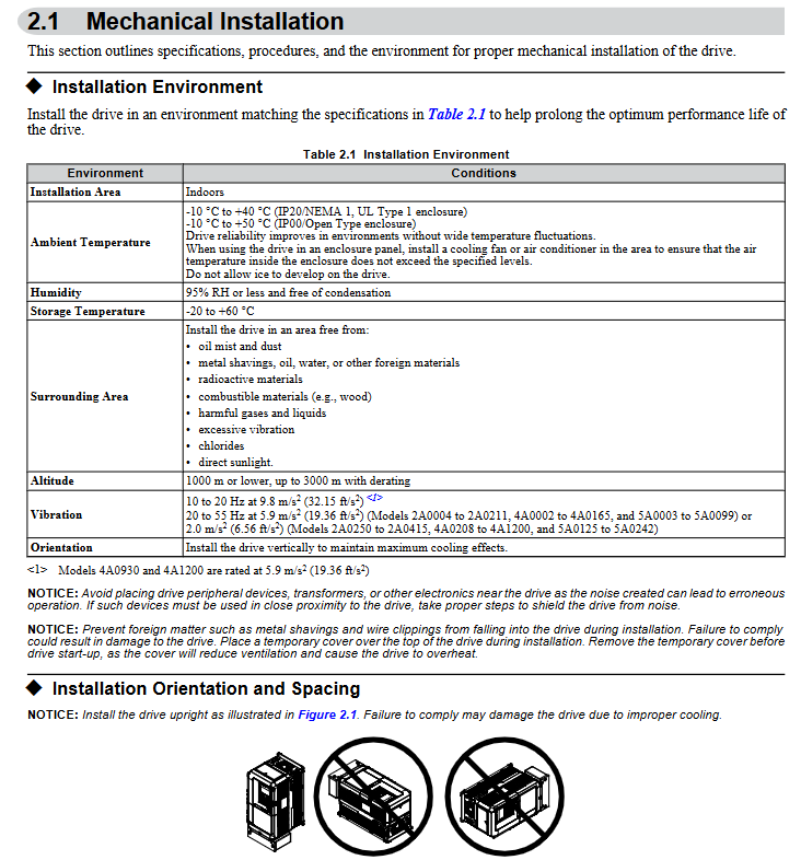
2. Installation method and spacing requirements
Installation direction: Only supports vertical installation. Tilting installation can cause poor heat dissipation and damage to internal components.
Single installation spacing:
Up and down direction: at least 50mm (heat dissipation space);
Left and right direction: at least 30mm (wiring and heat dissipation);
Rear: It should be tightly attached to the enclosed surface to avoid the dispersion of cooling airflow.
Multiple units installed side by side:
Only low-power models (such as 2A0004~2A0081, 4A0002~4A0044) are supported, and the parameter L8-35=1 (Side by Side mode) needs to be set;
The minimum spacing is 2mm, but capacity reduction needs to be considered and aligned with the top of the model to facilitate fan replacement.
3. Precautions for lifting and protection
Use of lifting rings: Some high-power models (such as 2A0360, 4A0250~4A1200) are equipped with lifting rings, and vertical lifting is only used for temporary installation. Long term suspension is prohibited; The lifting of 4A0930/4A1200 requires a suspension angle of ≥ 50 ° to avoid overloading of the lifting ring.
Protection level maintenance: After removing the top protective cover or bottom conduit bracket of IP20/NEMA 1 models, only IP20 protection is retained and NEMA 1 certification is lost.
Electrical installation: wiring specifications and safety requirements
1. Main circuit wiring (prevention and control of core risk points)
Terminal differentiation:
Input terminals (R/L1, S/L2, T/L3): connected to a three-phase power supply, matching the voltage level of the frequency converter (such as 200V level connected to 200-240V, 400V level connected to 380-480V);
Output terminals (U/T1, V/T2, W/T3): connected to the motor, the phase sequence determines the motor direction, and reverse can exchange any two phases ();
Brake terminals (B1, B2): only connect brake resistors/brake units, strictly prohibit connecting other devices.
Wiring requirements:
Wire specifications: Choose according to the rated current of the model. For example, the 2A0004 model uses 14AWG wire for the main circuit, and the 4A1200 model uses 300kcmil wire, and requires the use of ring crimping terminals (UL/cUL certification requirements);
Tightening torque: M4 screws 1.2-1.5N · m, M8 screws 9.9-11N · m. Overtightening may damage the terminals;
Grounding: separate grounding, not sharing grounding wire with high current equipment such as welding machines; The cross-sectional area of the grounding wire for models 4A0414 and above is ≥ 10mm ² (copper) or 16mm ² (aluminum).
2. Control circuit wiring (anti-interference and functional configuration)
Digital input (S1~S8):
Support sinking/sourcing mode, switched through SC-SP/SC-SN jumper, default sinking mode;
Default functions: S1 (forward rotation), S2 (reverse rotation), S3 (external fault), S4 (fault reset), customizable through H1 series parameters.
Analog inputs (A1~A3):
A1/A3 default voltage input (0~10V), A2 default current input (4~20mA), switched through jumper S1;
For frequency setting, it is necessary to set the gain (H3-03/H3-07/H3-11) and bias (H3-04/H3-08/H3-12) to match the signal range (,).
Communication interfaces (R+, R -, S+, S -):
Supports RS-422/RS-485 for MEMOBU/Modbus communication, with the maximum transmission distance being related to the baud rate (up to 115.2kbps);
The terminal resistor (DIP switch S2 set to ON) needs to be enabled at the end of the bus.
3. Handling of special wiring scenarios
Long cable wiring (>50 meters): It is necessary to reduce the carrier frequency (C6-02), set it below 5kHz for 50-100 meters, and below 2kHz for>100 meters to avoid leakage current through large trigger protection (,).
12 pulse rectification (4A0930/4A1200): The jumper wires between R/L1-R1/L11, S/L2-S1/L21, and T/L3-T1/L31 need to be removed, and an external 3-winding transformer (,) needs to be connected.

Start programming and operation: from parameter setting to trial run
1. Use of digital operator (core control interface)
Button functions:
RUN/STOP: Local start/stop, with the STOP key having the highest priority;
LO/RE: Switch between local/remote control, only operable during shutdown;
ESC/ENTER: Return to the previous level/confirm parameters, long press ESC to return to the frequency setting interface ().
Display interpretation:
Status display: "Rdy" (ready), "FWD/REV" (forward/reverse), ALM light (alarm/fault);
Monitoring interface: can view parameters such as output frequency (U1-02), output current (U1-03), PID feedback (U5-01), etc.
2. Core parameter configuration (classified by application scenario)
(1) Basic initialization
Parameter A1-03 (initialization parameter):
0: No initialization;
2220-2 wire system control initialization (S1 forward rotation, S2 reverse rotation);
3330:3 wire system control initialization (S1 start, S2 stop, S5 forward and reverse);
8008~8011: Fan/pump preset (,).
(2) Motor and load adaptation
E2-01 (rated current of motor): It must be strictly set according to the motor nameplate, and will automatically update after automatic tuning;
C1-01/C1-02 (Acceleration/Deceleration Time 1): It is recommended to set the fan/pump load to 60-90 seconds to avoid water/air flow impact;
B1-03 (shutdown mode): default "ramp shutdown" (C1-02), high inertia load can choose "DC injection braking" (b2-02 braking current needs to be set).
(3) Fan/pump specific function
PID control: parameter b5-01=1 enables PID, A2 terminal defaults to feedback signals (such as pressure and flow sensors), b5-19 sets PID setpoint (,);
EZ sleep/wake-up: parameter b5-89=1 enabled, b5-92 sets sleep frequency (such as 0Hz), b5-94 sets wake-up threshold to avoid frequent start stop and save energy (,);
Blockage protection: L3-01=1 (acceleration blockage protection), L3-04=1 (deceleration blockage protection), to avoid overload triggering overcurrent (,).
3. Auto Tuning
Function: Automatically detect motor parameters (stator resistance, leakage inductance, etc.), optimize V/f curve and control accuracy, recommended for first-time use.
Operation steps:
Set T1-01=2 (static tuning, measuring line resistance) or T1-02=3 (dynamic tuning, motor rotation);
Enter the motor nameplate parameters (T1-02 power, T1-04 current, T1-06 pole count, etc.);
Press the RUN key to start tuning, and after completion, display "Tune Successful" (,).
Attention: Dynamic tuning requires disconnecting the motor load to ensure that the motor can rotate freely; Long cables (>50 meters) require static tuning first.
4. Trial operation process (phased verification)
(1) No load trial operation
Step: Disconnect the motor from the load → Set as local control → Start at a given frequency of 6Hz → Check the motor direction, vibration, and current (should be 50% lower than the rated current) → Gradually increase the frequency to the rated value and observe the stability of operation (,).
(2) Test run with load
Preparation: Connect the load and confirm that the emergency stop circuit is effective;
Operation: Starting from low frequency (such as 20Hz), monitor the output current (U1-03), PID feedback (such as whether the pressure is stable), adjust PID parameters (b5-02 proportional gain, b5-03 integration time) to optimize response speed (,).
Troubleshooting and maintenance: ensuring long-term stable operation
1. Common faults and solutions
Possible causes and solutions for fault codes
OC (overcurrent) 1. Motor short circuit/insulation damage; 2. The acceleration and deceleration time is too short; 3. Load blockage 1. Check the motor winding; 2. Extend C1-01/C1-02; 3. Reduce load or increase model size
OV (overvoltage) 1. Input voltage is too high; 2. Slow down too quickly; 3. The braking resistor is not connected. 1. Check the power supply; 2. Extend C1-02 or activate stall protection; 3. Install the braking resistor
OL1 (motor overload) 1. E2-01 is set too low; 2. The load exceeds the rated torque of the motor. 1. Correct E2-01; 2. Verify the load or replace the large motor
FbL (PID feedback low) 1. Sensor disconnection; 2. Feedback signal not connected correctly. 1. Check the sensor and wiring; 2. Confirm the function of terminal A2 (H3-10=B)
2. Regular maintenance plan
(1) Daily inspection (daily)
Appearance: No abnormal noise, odor, or vibration;
Display: No alarm code, stable current/frequency;
Heat dissipation: The fan is running normally and there is no dust blockage.
(2) Regular maintenance (by cycle)
Maintenance project cycle operation requirements
Check the blade wear of the cooling fan after running for 20000 hours and replace it with a fan of the same model
Measure the capacitance of the main circuit capacitor after 5-7 years of operation. If it is lower than 80% of the initial value, it needs to be replaced
Check the torque of the main circuit terminals every 6 months to prevent looseness and heating during terminal tightening
Clean every 3 months by blowing compressed air to remove dust from the radiator (operated after power outage)
3. Maintain monitoring function
Parameters U4-01~U4-04: Display cooling fan, main capacitor IGBT、 The remaining lifespan (percentage) of the control circuit capacitor should be replaced in advance if it is less than 20%.

- YOKOGAWA
- Reliance
- ADVANCED
- SEW
- ProSoft
- WATLOW
- Kongsberg
- FANUC
- VSD
- DCS
- PLC
- man-machine
- Covid-19
- Energy and Gender
- Energy Access
- Renewable Integration
- Energy Subsidies
- Energy and Water
- Net zero emission
- Energy Security
- Critical Minerals
- A-B
- petroleum
- Mine scale
- Sewage treatment
- cement
- architecture
- Industrial information
- New energy
- Automobile market
- electricity
- Construction site
- HIMA
- ABB
- Rockwell
- Schneider Modicon
- Siemens
- xYCOM
- Yaskawa
- Woodward
- BOSCH Rexroth
- MOOG
- General Electric
- American NI
- Rolls-Royce
- CTI
- Honeywell
- EMERSON
- MAN
- GE
- TRICONEX
- Control Wave
- ALSTOM
- AMAT
- STUDER
- KONGSBERG
- MOTOROLA
- DANAHER MOTION
- Bentley
- Galil
- EATON
- MOLEX
- Triconex
- DEIF
- B&W
- ZYGO
- Aerotech
- DANFOSS
- KOLLMORGEN
- Beijer
- Endress+Hauser
- schneider
- Foxboro
- KB
- REXROTH
- YAMAHA
- Johnson
- Westinghouse
- WAGO
- TOSHIBA
- TEKTRONIX
- BENDER
- BMCM
- SMC
- HITACHI
- HIRSCHMANN
- XP POWER
- Baldor
- Meggitt
- SHINKAWA
- Other Brands
- UniOP
- KUKA
- IBA
- Beckhoff
- ADLINK
-
Beckhoff CX1100-0910 - Power Supply Module
-
Beckhoff C5210-0010 - Communication Module C5210
-
BECKHOFF KL1352 - Bus Terminal SET OF 2 FREE FAST SHIP
-
Beckhoff EL3058 - 8 x analog input single ended 4...20mA 85惟 shunt 12bit
-
Beckoff CX1100-0920 - UPS Module 24VDC (US SELLER) * *
-
BECKHOFF C6920-0000 - C69200000 PLC Moudule
-
Beckhoff CX5120-0115 - CPU controller module CX5120-0115
-
Unknown 15F5C1E-Y50A - Of Frequency Converters
-
Beckhoff AX5118-0000-0200 - Servo Drive HTP0
-
BECKHOFF AX5106-0000-0200 - Servo Drive
-
Beckhoff CX5240-0175 - Module (free) #U2327D YG
-
Beckhoff CP6607-0001-0000 - Compact PC Panel Economy Installation Operator 5,7 "
-
Beckhoff EP3744-0041 - 2022 EP37440041 Module
-
Beckhoff CP6209-0001-0020 - 6.5" PC Touch Screen Control Panel 24VDC
-
Beckhoff CX9020-0111 - /U900 +8x+2xEL3121+1x EL9410+3xEL1008+1x EL2008 Set
-
Beckhoff C6525-1030-0050 - Industrial PC
-
Beckoff CX1100-0920 - UPS Module 24VDC (US SELLER)
-
Beckhoff CX5010-0120 - CX5010 Processor Intel Atom Z510 B24
-
Siemens 6FC5203-0AF04-1BA1 - Operation Panel
-
Beckhoff CX5230-0175 - / 000029724 Embedded PC / Industrial PC on Rail
-
Beckhoff CP3916-0000 - industrielles Anzeige- und Bedienterminal
-
BECKHOFF CX1500-M310 - CX1000-N000 CX1000-0011 CX1000-C00L CX1100-0002 PLC Module
-
Beckhoff EL1872 - 16-channel digital input terminal
-
BECKHOFF EP2318-0001 - module
-
Beckhoff CX9020-0110 - Basic CPU Module
-
Beckhoff EL2564 - EtherCAT Terminal, 4-channel LED output, 5鈥?8VDC, 4A, RGBW
-
Beckhoff CX5130-0155 - /000105637 Automation Embedded PC
-
B&R 400 - Power Control Panel Rev D0 24 VDC
-
Beckhoff CX2020-0155 - module
-
Beckhoff CX9020-0115 - PLC Module
-
BECKHOFF EL6695 - PLC EL 6695
-
BECKHOFF EL7047 - PLC Modules
-
Beckhoff CX1000-0012 - Control HW 2.2 + CX1500-M310 + CX1000-C00L + CX1100-0002+
-
Beckhoff C6920-1039-0030 - control cabinet industrial PC CPU Celeron 1.90 GHz, 2 cores
-
BECKHOFF CX1100-0910 - PLC Module#
-
Beckhoff IL2301-B318-0000 - Coupler Box 4 Channel Digital Input |
-
Beckhoff CX7080 - Module
-
Beckhoff C6930-0060 - Industrial PC
-
Beckhoff CP7902-1060-0000 - Touchscreen 15 " CP7902
-
beckhoff CX9020-0111 - Controller module or UPS
-
Beckhoff CX8091 - PLC Module CX8091
-
Beckhoff C6640-1008-0030 - Control Cabinet Industrial PC
-
BECKHOFF CX1100-0920 - module
-
Beckhoff C9900-M921 - see pictures
-
BECKHOFF CP6829-0001-0000 - Touch Panel
-
BECKHOFF C6930-0060 - Industrial Computer
-
BECKHOFF CX8050 - PLC module
-
Beckhoff CP6202-0021-0020 - Touch Screen #
-
BECKHOFF AM3031-0C20-0000 - SERVO MOTOR
-
Unknown BCH1302N11A1C - Servo motor
-
Beckhoff EL2502 - 2-channel pulse width output terminal
-
Beckhoff EL6731 - Profibus Master / *Rev: 0025
-
Beckhoff CP3918-0010 - Control Panel
-
BECKHOFF CP2915-0010 - [24 MONTH WARRANTY] Control Panel
-
Beckhoff AX5203-0000-0202 - Servo Drive
-
Schneider TSXDSY64T2K - PLC OUTPUT MODULE
-
Beckhoff EP4174-0002 - Module-
-
Beckhoff IL2302-B318-0000 - Profibus Box
-
Beckhoff CP6709-0001-0000 - Touchpanel
-
BECKHOFF CX2030-0123 - Controller
-
Beckhoff CX9020-0111 - Processor Module
-
Beckhoff CX1020-0000 - CX Basic CPU Module
-
Beckhoff AX2003-AS - Servo Drive HTP0
-
Beckhoff C6240-1052-0040 - 4-086-06-3073 Industrial Computer CB1052-0003
-
Beckhoff EL1918 - 8 xTwinSAFE Input
-
Beckhoff AM8072-0R20-0000 - Servomotor
-
BECKHOFF AM8021-1B21-0000 - servo motor #T882 YS
-
Beckhoff EL6224 - 4 X Terminal IO-LINK
-
Beckhoff CX5140-0135 - embedded PC with Intel Atom processor 4 GB HW 3.6
-
Beckhoff CP7201-1000-0000 - Panel PC #
-
Beckhoff CX5130-0121 - Embedded-PC 4GB CPU Module HW 2.5 Industrial PC
-
Beckhoff AM8022-0D41-1002 - Servomotor
-
BECKHOFF CX2030-0130 - Module
-
BECKHOFF EL1872 - 16-channel digital input terminal
-
Unknown GXMMW.A203P33 - 1pc encoder
-
Beckhoff EL6631-0000 - EtherCAT Terminal 2-Port EL 6631
-
BECKHOFF C6925-0030 - Industrial Computer
-
Beckhoff CX8190 - A Module
-
BECKHOFF CX2040-0135 - CX2040-0135/000000927 CPU BASE MODULE i7 2715QE 2.1GHz --
-
BECKHOFF KL6023-0000 - Wireless adapter
-
Saia Burgess PCD7.F700 - PCD7F700 Communication Module
-
Beckhoff CX5130-0112 - CPU Module
-
BECKHOFF CX1020-N010 - CX1020-N000 CX1020-0111 CX1100-0004 EL2008 EL3064 EL4004
-
Beckhoff EP1819-0021 - A Module
-
Beckhoff CX2030-0120 - / 4gb with CX2100 0004
-
B&R X20-XC-0292 - Automation Powerlink Ethernet Bus Controller Module
-
Beckhoff BK3110 - One PLC Module
-
BECKHOFF KL3222 - PLC Module
-
BECKHOFF CX1500-M310 - CX1000-N000 CX1000-0011 CX1000-C00L CX1100-0002 PLC MODULE
-
Beckhoff CP3918-0010 - Control Panel
-
Beckhoff CX2030-0100-1002 - /4GB + CX2100 + CX2550 + CX2500-0060 + SSD
-
Beckhoff EP1816-0008 - PLC Module
-
Beckhoff CX5130-0112 - Module
-
Beckhoff Cx1500-m750 - CPU Hw: 1.4
-
BECKHOFF AX5112-0000-0200 - AX511200000200 Servo Driver
-
Beckhoff EL3751 - EtherCAT Terminal 1 Channel Analog Input Multifunction 24 Bit
-
Beckhoff CX1100-0002 - Power Supply Module
-
Beckhoff CP3916-1016-0010 - Control Panel
-
BECKHOFF CX9001-1101 - #NAME?
-
Beckhoff EP3174-0002 - EtherCAT Box Module
-
Beckhoff C6030-0070 - servo drive
-
Beckhoff CX2020-0120 - /4GB CPU, CX2100-0904, 3x EL6900, EL1904, 16GB Memory
-
BECKHOFF C6110 - BOX-PC 113608
-
BECKHOFF EK1914 - module #P
-
Beckhoff C6140 - Ipox IP-4GVI63 + CH7009A_DVI_TV + SIEMENS A5E00369843 + WD800AAJB
-
Beckhoff CX5020-0111 - controller Good quality
-
BECKHOFF C6015-0010 - / 6559380 ULTRA-COMPACT INDUSTRIAL PC ()
-
Beckhoff AX5203-0000-0200 - PLC module
-
Beckhoff EL2872 - 16-channel digital output terminal
-
BECKHOFF C3640-0000 - Panel Industrial PC 100/240VAC 128MB E0122L
-
Beckhoff CX8031 - Module
-
Beckhoff CX5020-0120-1002 - PLC module#
-
Beckhoff C6140 - M845B + SIEMENS A5E00369843 + C9900_A159_1 + AUTOMATA CAN PCI 1N
-
BECKHOFF AX5112-0000-0200 - Servo Drive*ie
-
B&R ECPA42-01 - Analog Output Module 4-Channel, +/- 10V Output Signal, 20mA Max
-
Beckhoff EL6631-0010 - PLC Module
-
BECKHOFF C6930-0070 - CONTROL CABINET INDUSTRIAL PC
-
BECKHOFF AX5112-0000-0200 - AX511200000200 Servo Driver
-
BECKHOFF EK9000 - Programmable Logic Controller Module EK9000 EK9000
-
BECKHOFF C6920-1028-0000 - Industrial computer
-
Beckhoff CX2030-0120 - controller Module
-
Beckhoff BX8000-0000 - Bus Terminal Controller HW 4.4
-
B&R 3NC154.60-2 - Positioning Module#
-
BECKHOFF CX1020-0122 - PLC module
-
Beckhoff AM3032-0D40-0000 - Servo Motor
-
BECKHOFF CX5020-0111 - CPU Module CX5020-0111
-
Beckhoff CB1051 - G5 Motherboard
-
BECKHOFF KL2641 - 1-channel relay output terminal

K-JIANG

Add: Jimei North Road, Jimei District, Xiamen, Fujian, China
Tell:+86-15305925923