
K-WANG


YASKAWA Power Regenerative Unit R1000 Series
400V three-phase series: models 4A03P5~4A0300, suitable for motor power of 5~422HP, rated output current of 7~629A;
All models are designed for "Normal Duty" and optimized for energy regeneration scenarios with variable torque loads.
Core features: Supports 120 ° excitation control, MEMOBU/Modbus communication, PID closed-loop control, automatic fault restart, maintenance life monitoring, and complies with international standards such as UL 508C, IEC/EN 61800-5-1, as well as CE and RoHS compliance requirements.
YASKAWA Power Regenerative Unit R1000 Series
Core specifications of the product
Model coverage:
200V three-phase series: models 2A03P5~2A0105, suitable for motor power of 5~141HP, rated output current of 14~413A;
400V three-phase series: models 4A03P5~4A0300, suitable for motor power of 5~422HP, rated output current of 7~629A;
All models are designed for "Normal Duty" and optimized for energy regeneration scenarios with variable torque loads.
Core features: Supports 120 ° excitation control, MEMOBU/Modbus communication, PID closed-loop control, automatic fault restart, maintenance life monitoring, and complies with international standards such as UL 508C, IEC/EN 61800-5-1, as well as CE and RoHS compliance requirements.
Receiving and unboxing inspection
1. Safety precautions
It is prohibited to transport equipment through the front cover or terminal cover to avoid damage caused by the main body falling;
When handling equipment and circuit boards, it is necessary to follow the electrostatic discharge (ESD) process to prevent circuit damage.
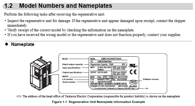
2. Model and nameplate verification
Key information on the nameplate: model (such as CIMR-RU2A0073AAA), rated capacity, input/output specifications, software version, serial number, and place of origin (Japan);
Model interpretation: Taking "CIMR-RU2A0073AAA" as an example, "RU" represents the R1000 series, "2A" is the 200V level, "0073" is the rated output capacity code, and "AAA" is the standard configuration.
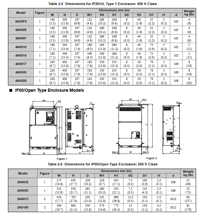
3. Classification of enclosure types
IP20/UL Type 1: Suitable for indoor wall mounted or control cabinet installation, retaining IP20 protection even after removing the top protective cover;
IP00/Open Type: It needs to be installed inside a protective panel, without additional shell protection, and relies on external environmental isolation.
Mechanical Installation: Environmental Requirements and Operating Standards
1. Installation environment requirements
Specific requirements for environmental dimensions: Remarks
Temperature IP00 model: -10~+50 ℃; IP20 model: -10~+40 ℃ overheating requires capacity reduction to avoid severe temperature fluctuations
Humidity ≤ 95% RH, no condensation to prevent moisture and short circuit of the circuit board
Altitude ≤ 1000 meters (without capacity reduction); 1000~3000 meters: For every 100 meters increase, the capacity is reduced by 1%. At high altitudes, the heat dissipation capacity needs to be evaluated
Vibration low-power models (2A03P5~2A0053, etc.): 10-20Hz (9.8m/s ²), 20-55Hz (5.9m/s ²); High power models (2A0073~2A0105, etc.): 20~55Hz (2.0m/s ²) Avoid direct contact with vibration sources
The surrounding environment should be free of dust, oil mist, metal debris, corrosive gases, and direct sunlight. Installation on flammable surfaces or placement of flammable materials is prohibited
2. Installation method and spacing requirements
Installation direction: Only supports vertical installation. Tilting can cause poor heat dissipation and damage to internal components.
Single installation spacing:
Up and down direction: at least 120mm (heat dissipation space);
Left and right direction: at least 30mm (wiring and heat dissipation);
Rear: It should be tightly attached to the enclosed surface to avoid the dispersion of cooling airflow.
Side by side installation (with drive):
Ordinary side by side: minimum spacing of 50mm, top aligned;
Tightly side by side (only for low-power models 2A03P5~2A0028, etc.): spacing of 2mm, parameter L8-35=1 needs to be set, while considering capacity reduction.
3. Precautions for lifting and protection
High power models (2A0073, 2A0105, etc.) are equipped with lifting rings and are only used for temporary installation. Long term suspension is prohibited;
When lifting vertically, it is necessary to first fix the front cover, terminal block and other components. The vibration/impact during suspension should not exceed 1.96m/s ², and flipping or leaving unattended is prohibited.
Electrical installation: wiring specifications and safety requirements
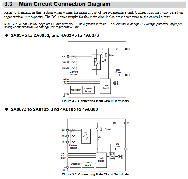
1. Main circuit wiring (prevention and control of core risk points)
Terminal differentiation:
Input terminals (R/L1, S/L2, T/L3): connected to three-phase power supply, matched with equipment voltage level (200V level connected to 200~240V, 400V level connected to 380~480V);
Output terminals (+, -): Connect to the DC bus of the driver, be careful not to reverse the positive and negative poles;
Voltage detection terminals (r1/11, l/21, t1/31): detect the phase sequence and voltage of the input power supply, and take power from the primary side of the power coordination reactor.
Wiring requirements:
Wire specifications: Select according to the rated current of the model. For example, 2A03P5 uses 14AWG (American standard) or 3.5mm ² (European standard) wire, 4A0300 uses 300kcmil wire, and circular crimping terminals are required;
Tightening torque: M4 screws 2.1~2.3N · m, M8 screws 5.4~6.0N · m, excessive tightening may damage the terminals;
Grounding: Independently grounded, not sharing grounding wire with high current equipment such as welding machines; Grounding resistance of 200V level ≤ 100 Ω, 400V level ≤ 10 Ω.
2. Control circuit wiring (anti-interference and functional configuration)
Digital input (S1~S8):
Support sinking/sourcing mode, switched through SC-SP/SC-SN jumper, default sinking mode;
Default functions: S1 (forced operation), S2 (automatic operation), S3 (external fault), S4 (fault reset), customizable through H1 series parameters.
Analog inputs (A1~A3):
A1/A3 default voltage input (0~10V/-10~10V), A2 default current input (4~20mA), switched through DIP switch S1;
For signal assignment, it is necessary to set the gain (H3-03/H3-07/H3-11) and bias (H3-04/H3-08/H3-12) to match the signal range.
Communication interfaces (R+, R -, S+, S -):
Supports RS-422/RS-485 for MEMOBU/Modbus communication, with the maximum transmission distance being related to the baud rate (up to 115.2kbps);
The terminal resistor needs to be enabled at the end of the bus (DIP switch S2 set to ON), and the communication line needs to be wired separately from the main power line.
3. Handling of special wiring scenarios
Long cable wiring: When the length of the control circuit analog signal line is ≤ 50 meters, and the main circuit cable is>50 meters, the carrier frequency should be reduced to avoid leakage current flowing through the large trigger protection;
12 pulse rectification configuration: The 4A0930/4A1200 models require the removal of jumper wires such as R/L1-R1/L11, and an external 3-winding transformer.
Start programming and operation: from parameter setting to trial run
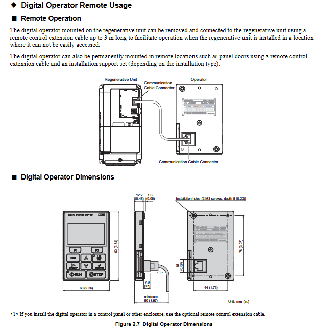
1. Use of digital operator (core control interface)
Button functions:
RUN/STOP: Local start/stop, with the STOP key having the highest priority;
LO/RE: Switch between local/remote control, only operable during shutdown;
F1/F2: Switch display data/help menu, ESC returns to the previous level, ENTER confirms parameters.
Display interpretation:
Status display: "Rdy" (ready), "FWD/REV" (forward/reverse), ALM light (alarm/fault);
Monitoring interface: can view parameters such as DC bus voltage (U1-52), input current (U1-55), power (U1-57), etc.
2. Core parameter configuration (classified by application scenario)
(1) Basic initialization
Parameter A1-03 (initialization parameter):
0: No initialization;
1110: User defined initialization;
2220: 2-wire control initialization;
3330:3 wire system control initialization;
5550: oPE04 fault reset.
(2) Operation mode and control configuration
B1-02 (run command selection): 0 (numeric operator), 1 (numeric input), 2 (communication), 3 (tab);
C7-16 (minimum running time): In forced running mode, set the minimum holding time from start to stop (default 1.00 seconds);
L5-01 (number of fault restarts): 0-10 times, supports automatic restarts after overcurrent, overvoltage and other faults.
(3) Protection parameter configuration
L2-05 (undervoltage detection level): default 190V for 200V level, default 380V for 400V level, adjustable as needed;
L8-02 (overheating alarm level): default 85~140 ℃ (random variation), exceeding this temperature triggers an oH alarm;
L8-35 (installation method selection): 0 (IP00 model), 1 (tightly arranged), 2 (IP20 model), 3 (external heat sink).
3. Trial operation process (phased verification)
(1) No load trial operation
Step: Disconnect the load → Set as local control → Set low frequency (such as 6Hz) → Start the equipment → Check the motor direction, vibration, and current (should be 50% lower than the rated current) → Gradually increase the frequency to the rated value and observe the stability of operation.
(2) Test run with load
Preparation: Connect the load, confirm that the emergency stop circuit is effective, and check the PID feedback signals (such as pressure and flow sensors);
Operation: Start from low frequency (such as 20Hz), monitor input current (U1-55), DC bus voltage (U1-52), adjust PID parameters (b5-02 proportional gain, b5-03 integration time) to optimize response speed.
Troubleshooting and maintenance: ensuring long-term stable operation
1. Common faults and solutions
Possible causes and solutions for fault codes
OC (overcurrent) motor short circuit/insulation damage, short acceleration and deceleration time, load blockage check motor winding, extend acceleration and deceleration time, reduce load or increase model size
OV (overvoltage) input voltage is too high, deceleration is too fast, brake resistor is not connected, check power supply, prolong deceleration time, install brake resistor
OL2 (overload) load exceeds rated torque, excessive regenerative energy reduces load, optimizes regenerative energy distribution, and replaces high-capacity models
CE (communication error) loose communication line, mismatched baud rate, noise interference check wiring, unified communication parameters, strengthened shielding and grounding
EF3 (external fault S3) S3 terminal wiring error, external device fault verification H1-03 parameter setting, troubleshooting external device faults
2. Regular maintenance plan
(1) Daily inspection (daily)
Appearance: No abnormal noise, odor, or vibration, and the cooling fan is running normally;
Display: No alarm code, stable parameters such as current and voltage;
Environment: Confirm that the temperature and humidity meet the installation requirements and there is no dust accumulation.
(2) Regular maintenance (by cycle)
Maintenance project cycle operation requirements
Check the blade wear of the cooling fan after running for 20000 hours or 10 years, replace it with a fan of the same model, and reset the parameter o4-03
Measure the capacitance of the main circuit capacitor after 5-7 years of operation. If it is lower than 80% of the initial value, it needs to be replaced. Monitor the lifespan through U4-05
Check the torque of the main and control circuit terminals every 6 months to prevent looseness and heating during terminal tightening
Clean the radiator with compressed air every 3 months after power failure to avoid clogging the air duct
3. Maintain monitoring function
Parameters U4 series: U4-03 (fan running time), U4-04 (fan life percentage), U4-05 (capacitor life percentage), U4-06 (soft charging relay life). If it is less than 20%, it needs to be replaced in advance.
Peripheral equipment and communication configuration
1. Standard configuration and peripheral equipment
Required equipment: power coordination reactor, current suppression reactor, fuse (model needs to be matched according to the model);
Optional devices: 24V power supply (PS-A10LB/HB), USB replication unit (JVOP-181), LED operator (JVOP-182), communication tab (MECHATROLINK-II, CC Link, etc.).
2. MEMOBU/Modbus communication configuration
Communication parameters:
H5-01 (slave address): 0~FFH, default 1FH, ensure unique address;
H5-02 (baud rate): 0 (1200bps)~8 (115200bps), default 3 (9600bps);
H5-03 (checksum): 0 (no checksum), 1 (even checksum), 2 (odd checksum), default 0.
Communication function: Supports reading monitoring data, writing parameters, controlling operation/stop, fault reset, and can be remotely controlled through PLC or upper computer.
- YOKOGAWA
- Reliance
- ADVANCED
- SEW
- ProSoft
- WATLOW
- Kongsberg
- FANUC
- VSD
- DCS
- PLC
- man-machine
- Covid-19
- Energy and Gender
- Energy Access
- Renewable Integration
- Energy Subsidies
- Energy and Water
- Net zero emission
- Energy Security
- Critical Minerals
- A-B
- petroleum
- Mine scale
- Sewage treatment
- cement
- architecture
- Industrial information
- New energy
- Automobile market
- electricity
- Construction site
- HIMA
- ABB
- Rockwell
- Schneider Modicon
- Siemens
- xYCOM
- Yaskawa
- Woodward
- BOSCH Rexroth
- MOOG
- General Electric
- American NI
- Rolls-Royce
- CTI
- Honeywell
- EMERSON
- MAN
- GE
- TRICONEX
- Control Wave
- ALSTOM
- AMAT
- STUDER
- KONGSBERG
- MOTOROLA
- DANAHER MOTION
- Bentley
- Galil
- EATON
- MOLEX
- Triconex
- DEIF
- B&W
- ZYGO
- Aerotech
- DANFOSS
- KOLLMORGEN
- Beijer
- Endress+Hauser
- schneider
- Foxboro
- KB
- REXROTH
- YAMAHA
- Johnson
- Westinghouse
- WAGO
- TOSHIBA
- TEKTRONIX
- BENDER
- BMCM
- SMC
- HITACHI
- HIRSCHMANN
- XP POWER
- Baldor
- Meggitt
- SHINKAWA
- Other Brands
- UniOP
- KUKA
- IBA
- Beckhoff
- ADLINK
-
Beckhoff CX1100-0910 - Power Supply Module
-
Beckhoff C5210-0010 - Communication Module C5210
-
BECKHOFF KL1352 - Bus Terminal SET OF 2 FREE FAST SHIP
-
Beckhoff EL3058 - 8 x analog input single ended 4...20mA 85惟 shunt 12bit
-
Beckoff CX1100-0920 - UPS Module 24VDC (US SELLER) * *
-
BECKHOFF C6920-0000 - C69200000 PLC Moudule
-
Beckhoff CX5120-0115 - CPU controller module CX5120-0115
-
Unknown 15F5C1E-Y50A - Of Frequency Converters
-
Beckhoff AX5118-0000-0200 - Servo Drive HTP0
-
BECKHOFF AX5106-0000-0200 - Servo Drive
-
Beckhoff CX5240-0175 - Module (free) #U2327D YG
-
Beckhoff CP6607-0001-0000 - Compact PC Panel Economy Installation Operator 5,7 "
-
Beckhoff EP3744-0041 - 2022 EP37440041 Module
-
Beckhoff CP6209-0001-0020 - 6.5" PC Touch Screen Control Panel 24VDC
-
Beckhoff CX9020-0111 - /U900 +8x+2xEL3121+1x EL9410+3xEL1008+1x EL2008 Set
-
Beckhoff C6525-1030-0050 - Industrial PC
-
Beckoff CX1100-0920 - UPS Module 24VDC (US SELLER)
-
Beckhoff CX5010-0120 - CX5010 Processor Intel Atom Z510 B24
-
Siemens 6FC5203-0AF04-1BA1 - Operation Panel
-
Beckhoff CX5230-0175 - / 000029724 Embedded PC / Industrial PC on Rail
-
Beckhoff CP3916-0000 - industrielles Anzeige- und Bedienterminal
-
BECKHOFF CX1500-M310 - CX1000-N000 CX1000-0011 CX1000-C00L CX1100-0002 PLC Module
-
Beckhoff EL1872 - 16-channel digital input terminal
-
BECKHOFF EP2318-0001 - module
-
Beckhoff CX9020-0110 - Basic CPU Module
-
Beckhoff EL2564 - EtherCAT Terminal, 4-channel LED output, 5鈥?8VDC, 4A, RGBW
-
Beckhoff CX5130-0155 - /000105637 Automation Embedded PC
-
B&R 400 - Power Control Panel Rev D0 24 VDC
-
Beckhoff CX2020-0155 - module
-
Beckhoff CX9020-0115 - PLC Module
-
BECKHOFF EL6695 - PLC EL 6695
-
BECKHOFF EL7047 - PLC Modules
-
Beckhoff CX1000-0012 - Control HW 2.2 + CX1500-M310 + CX1000-C00L + CX1100-0002+
-
Beckhoff C6920-1039-0030 - control cabinet industrial PC CPU Celeron 1.90 GHz, 2 cores
-
BECKHOFF CX1100-0910 - PLC Module#
-
Beckhoff IL2301-B318-0000 - Coupler Box 4 Channel Digital Input |
-
Beckhoff CX7080 - Module
-
Beckhoff C6930-0060 - Industrial PC
-
Beckhoff CP7902-1060-0000 - Touchscreen 15 " CP7902
-
beckhoff CX9020-0111 - Controller module or UPS
-
Beckhoff CX8091 - PLC Module CX8091
-
Beckhoff C6640-1008-0030 - Control Cabinet Industrial PC
-
BECKHOFF CX1100-0920 - module
-
Beckhoff C9900-M921 - see pictures
-
BECKHOFF CP6829-0001-0000 - Touch Panel
-
BECKHOFF C6930-0060 - Industrial Computer
-
BECKHOFF CX8050 - PLC module
-
Beckhoff CP6202-0021-0020 - Touch Screen #
-
BECKHOFF AM3031-0C20-0000 - SERVO MOTOR
-
Unknown BCH1302N11A1C - Servo motor
-
Beckhoff EL2502 - 2-channel pulse width output terminal
-
Beckhoff EL6731 - Profibus Master / *Rev: 0025
-
Beckhoff CP3918-0010 - Control Panel
-
BECKHOFF CP2915-0010 - [24 MONTH WARRANTY] Control Panel
-
Beckhoff AX5203-0000-0202 - Servo Drive
-
Schneider TSXDSY64T2K - PLC OUTPUT MODULE
-
Beckhoff EP4174-0002 - Module-
-
Beckhoff IL2302-B318-0000 - Profibus Box
-
Beckhoff CP6709-0001-0000 - Touchpanel
-
BECKHOFF CX2030-0123 - Controller
-
Beckhoff CX9020-0111 - Processor Module
-
Beckhoff CX1020-0000 - CX Basic CPU Module
-
Beckhoff AX2003-AS - Servo Drive HTP0
-
Beckhoff C6240-1052-0040 - 4-086-06-3073 Industrial Computer CB1052-0003
-
Beckhoff EL1918 - 8 xTwinSAFE Input
-
Beckhoff AM8072-0R20-0000 - Servomotor
-
BECKHOFF AM8021-1B21-0000 - servo motor #T882 YS
-
Beckhoff EL6224 - 4 X Terminal IO-LINK
-
Beckhoff CX5140-0135 - embedded PC with Intel Atom processor 4 GB HW 3.6
-
Beckhoff CP7201-1000-0000 - Panel PC #
-
Beckhoff CX5130-0121 - Embedded-PC 4GB CPU Module HW 2.5 Industrial PC
-
Beckhoff AM8022-0D41-1002 - Servomotor
-
BECKHOFF CX2030-0130 - Module
-
BECKHOFF EL1872 - 16-channel digital input terminal
-
Unknown GXMMW.A203P33 - 1pc encoder
-
Beckhoff EL6631-0000 - EtherCAT Terminal 2-Port EL 6631
-
BECKHOFF C6925-0030 - Industrial Computer
-
Beckhoff CX8190 - A Module
-
BECKHOFF CX2040-0135 - CX2040-0135/000000927 CPU BASE MODULE i7 2715QE 2.1GHz --
-
BECKHOFF KL6023-0000 - Wireless adapter
-
Saia Burgess PCD7.F700 - PCD7F700 Communication Module
-
Beckhoff CX5130-0112 - CPU Module
-
BECKHOFF CX1020-N010 - CX1020-N000 CX1020-0111 CX1100-0004 EL2008 EL3064 EL4004
-
Beckhoff EP1819-0021 - A Module
-
Beckhoff CX2030-0120 - / 4gb with CX2100 0004
-
B&R X20-XC-0292 - Automation Powerlink Ethernet Bus Controller Module
-
Beckhoff BK3110 - One PLC Module
-
BECKHOFF KL3222 - PLC Module
-
BECKHOFF CX1500-M310 - CX1000-N000 CX1000-0011 CX1000-C00L CX1100-0002 PLC MODULE
-
Beckhoff CP3918-0010 - Control Panel
-
Beckhoff CX2030-0100-1002 - /4GB + CX2100 + CX2550 + CX2500-0060 + SSD
-
Beckhoff EP1816-0008 - PLC Module
-
Beckhoff CX5130-0112 - Module
-
Beckhoff Cx1500-m750 - CPU Hw: 1.4
-
BECKHOFF AX5112-0000-0200 - AX511200000200 Servo Driver
-
Beckhoff EL3751 - EtherCAT Terminal 1 Channel Analog Input Multifunction 24 Bit
-
Beckhoff CX1100-0002 - Power Supply Module
-
Beckhoff CP3916-1016-0010 - Control Panel
-
BECKHOFF CX9001-1101 - #NAME?
-
Beckhoff EP3174-0002 - EtherCAT Box Module
-
Beckhoff C6030-0070 - servo drive
-
Beckhoff CX2020-0120 - /4GB CPU, CX2100-0904, 3x EL6900, EL1904, 16GB Memory
-
BECKHOFF C6110 - BOX-PC 113608
-
BECKHOFF EK1914 - module #P
-
Beckhoff C6140 - Ipox IP-4GVI63 + CH7009A_DVI_TV + SIEMENS A5E00369843 + WD800AAJB
-
Beckhoff CX5020-0111 - controller Good quality
-
BECKHOFF C6015-0010 - / 6559380 ULTRA-COMPACT INDUSTRIAL PC ()
-
Beckhoff AX5203-0000-0200 - PLC module
-
Beckhoff EL2872 - 16-channel digital output terminal
-
BECKHOFF C3640-0000 - Panel Industrial PC 100/240VAC 128MB E0122L
-
Beckhoff CX8031 - Module
-
Beckhoff CX5020-0120-1002 - PLC module#
-
Beckhoff C6140 - M845B + SIEMENS A5E00369843 + C9900_A159_1 + AUTOMATA CAN PCI 1N
-
BECKHOFF AX5112-0000-0200 - Servo Drive*ie
-
B&R ECPA42-01 - Analog Output Module 4-Channel, +/- 10V Output Signal, 20mA Max
-
Beckhoff EL6631-0010 - PLC Module
-
BECKHOFF C6930-0070 - CONTROL CABINET INDUSTRIAL PC
-
BECKHOFF AX5112-0000-0200 - AX511200000200 Servo Driver
-
BECKHOFF EK9000 - Programmable Logic Controller Module EK9000 EK9000
-
BECKHOFF C6920-1028-0000 - Industrial computer
-
Beckhoff CX2030-0120 - controller Module
-
Beckhoff BX8000-0000 - Bus Terminal Controller HW 4.4
-
B&R 3NC154.60-2 - Positioning Module#
-
BECKHOFF CX1020-0122 - PLC module
-
Beckhoff AM3032-0D40-0000 - Servo Motor
-
BECKHOFF CX5020-0111 - CPU Module CX5020-0111
-
Beckhoff CB1051 - G5 Motherboard
-
BECKHOFF KL2641 - 1-channel relay output terminal

K-JIANG

Add: Jimei North Road, Jimei District, Xiamen, Fujian, China
Tell:+86-15305925923