
K-WANG


Foxboro PBCO-D8-009 Terminal Board (TB)
Foxboro PBCO-D8-009 Terminal Board (TB)
Product basic positioning and core role
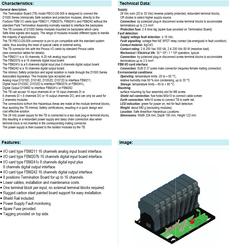
PBCO-D8-009 is a Termination Board (TB) launched by G.M. International. Its core function is to directly connect D1000 series intrinsic safety isolation and protection modules, and interface with Foxboro FBM series I/O cards (FBM211, FBM207b, FBM241c, FBM242). It can achieve backplane interface connection without the need for conventional Field Termination Assembly, simplifying the signal transmission link between safe and dangerous areas in industrial control systems, and combining cost-effectiveness and design convenience.
Compatible device and module configuration
(1) Compatible FBM I/O card types and parameters
The terminal board provides dedicated interfaces for FBM cards of different signal types, and the functions and channel configurations of each card are as follows:
FBM I/O card model type channel configuration core purpose
FBM211 Analog Input (AI) board with 16 channels, 4-20mA signal reception for on-site analog signals (such as sensor data)
FBM207b digital input (DI) board 16 channels receive on-site digital input signals (such as switch status, proximity sensor signals)
FBM241c digital input/output (DI/DO) board with 8 channels DI+8 channels DO simultaneously receives digital input signals and outputs control signals (such as driving solenoid valves)
FBM242 digital output (DO) board 16 channel output digital control signals (such as control actuators, indicator lights)
(2) Matching D1000 series modules
The terminal board needs to be equipped with D1000 series intrinsic safety modules to achieve signal isolation and protection. The module types corresponding to different I/O cards are fixed, as follows:
FBM I/O card model matches D1000 module type module function
FBM211 (analog input) D100D, D104D, D1052D, D1072D analog signal isolation, supports 4-20mA signal transmission, some modules (D101D/D104D) are compatible with HART protocol
FBM207b (digital input), FBM241c (DI part) D1030D, D1032D digital input signal isolation, suitable for voltage contactless signals and proximity sensor signals
FBM241c (DO section), FBM242 (digital output) D1049D digital output signal isolation, driving solenoid valves and other loads, supporting load diagnosis
(3) Channel capacity limitation
The terminal board only supports 2-channel modules, and a single TB can achieve any of the following channel configurations:
16 channel analog input (AI)
16 channel digital input (DI)
8-channel digital input+8-channel digital output (DI+DO)
16 channel digital output (DO)
Core Features and Product Highlights
Simplified wiring and compatibility:
The terminal board connector is pin compatible with standard system cables, without the need for dedicated cables or additional external wiring; Connect with Provox I/O cards through standard Provox cables to reduce wiring complexity and cost.
Intrinsic safety and isolation protection:
Relying on D1000 series associated devices to achieve intrinsic safety protection and signal isolation, the connection between hazardous and safe areas is only completed through module terminal blocks, and the terminal board does not require separate intrinsic safety certification, shortening the design cycle.
Redundant power supply and flexible expansion:
The 24Vdc power supply is connected through a dual plug terminal block, supporting redundant power supply and daisy chain connection (even if the terminal block is not plugged into the corresponding matching connector). The power supply is distributed to the isolation module through the terminal board bus to ensure power supply stability.
Convenient installation and maintenance:
Equipped with sturdy carbon steel painted plate bracket, supporting surface installation (4 M6 screw mounting slots);
Equipped with Shield Rail, 5 M5x10 holes for cable shielding layer connection, and 1 M4x10 screw for grounding;
Provide backup fuses (2A delay type), power failure monitoring function, and support label labeling at the top to reduce maintenance difficulty.
Status visualization:
Equipped with LED indicator lights - green indicates normal power supply, red indicates fault detection (such as abnormal power supply voltage), providing intuitive feedback on equipment operation status.
Technical specifications and parameters
(1) Power Supply and Protection
Parameter category specific specifications
Power input nominal 24Vdc, input range 20-30Vdc, with reverse polarity protection
The power selection has a built-in OR diode, which can automatically select a higher voltage power source
Protection fuse 2A delay type (onboard backup fuse)
Fault detection power supply voltage fault threshold: ≤ 18Vdc; The fault signal is output through the contact of the NE SPDT relay without voltage (the relay loses power in case of fault)
Relay parameter contact material: AgCdO; Contact rating: 2A 250Vac (500VA), 2A 250Vdc (80W, resistive load); Mechanical lifespan 3 × 10 ⁶ times, electrical lifespan 1 × 10 ⁵ times
(2) Connection interface
Interface type specification and purpose
Terminal block polarized plug-in disconnect screw terminal block, supporting up to 2.5mm ² wire
FBM I/O card interface SUB D 37 pin male connector (to be used with female connector)
Shielding and grounding shielding rails (5 M5x10 holes), grounding screws (M4x10)
(3) Environmental and Physical Characteristics
Parameter category specific specifications
Working environment temperature: -20~+60 ° C; relative humidity: ≤ 90% (below 35 ° C, no condensation)
Storage environment temperature: -45~+80 ° C
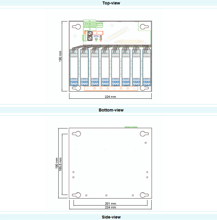
Installation method: Surface installation
Dimensions (width x depth x height) 224mm x 190mm x 122mm
Weight approximately 940g (excluding modules)
Applicable Area: Safe Zone/Non Hazardous Zone
Wiring and Circuit Design
The document provides detailed loop diagrams and connection tables, clarifying the signal flow direction between the HAZARDOUS Area and the SAFE Area. The core wiring logic is as follows:
(1) FBM211 (16AI) and FBM207b (16DI)
FBM211: Equipped with analog modules such as D1014D, hazardous area field equipment (such as 4-20mA transmitters) is connected through the module terminal block, and the signal is isolated and transmitted to the corresponding channel of FBM211. Some modules support HART multiplexer.
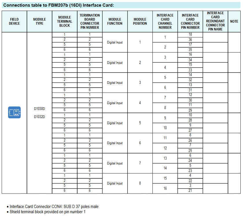
FBM207b: Equipped with digital modules such as D1032D, the voltage non-contact signal and proximity sensor signal in the hazardous area are isolated by the module and connected to the digital input channel of FBM207b.
(2) FBM241c (8DI+8DO) and FBM242 (16DO)
FBM241c: DI section (terminal board positions 1-4) is equipped with D1032D module to connect digital input signals; The DO section (terminal board positions 5-8) is equipped with D1049D module, which outputs signals to drive hazardous area solenoid valves and other loads, supporting load diagnosis.
FBM242: The full channel (terminal board positions 1-8) is equipped with D1049D module to output digital control signals to hazardous area loads (such as solenoid valves). The module is responsible for signal isolation and load status monitoring.
All wiring tables clearly indicate the corresponding relationship between "field equipment module terminal block terminal board connector pins FBM card channel redundant connector pins", and the FBM card interface (CON4) is a SUB D 37 pin male connector, with the shielding layer uniformly connected to the shielding terminal block of pin 1.
Order Information
Product Model: PBCO-D8-009
Product Description: 8-bit terminal board, compatible with Foxboro FBM I/O cards (FBM211, FBM207b, FBM241c, FBM242), required to be used with D1000 series intrinsic safety modules.
- YOKOGAWA
- Reliance
- ADVANCED
- SEW
- ProSoft
- WATLOW
- Kongsberg
- FANUC
- VSD
- DCS
- PLC
- man-machine
- Covid-19
- Energy and Gender
- Energy Access
- Renewable Integration
- Energy Subsidies
- Energy and Water
- Net zero emission
- Energy Security
- Critical Minerals
- A-B
- petroleum
- Mine scale
- Sewage treatment
- cement
- architecture
- Industrial information
- New energy
- Automobile market
- electricity
- Construction site
- HIMA
- ABB
- Rockwell
- Schneider Modicon
- Siemens
- xYCOM
- Yaskawa
- Woodward
- BOSCH Rexroth
- MOOG
- General Electric
- American NI
- Rolls-Royce
- CTI
- Honeywell
- EMERSON
- MAN
- GE
- TRICONEX
- Control Wave
- ALSTOM
- AMAT
- STUDER
- KONGSBERG
- MOTOROLA
- DANAHER MOTION
- Bentley
- Galil
- EATON
- MOLEX
- Triconex
- DEIF
- B&W
- ZYGO
- Aerotech
- DANFOSS
- KOLLMORGEN
- Beijer
- Endress+Hauser
- schneider
- Foxboro
- KB
- REXROTH
- YAMAHA
- Johnson
- Westinghouse
- WAGO
- TOSHIBA
- TEKTRONIX
- BENDER
- BMCM
- SMC
- HITACHI
- HIRSCHMANN
- XP POWER
- Baldor
- Meggitt
- SHINKAWA
- Other Brands
- UniOP
- KUKA
- IBA
- Beckhoff
- ADLINK
-
ADLINK HPCI-14S12U - Industrial Control Backplane 12PCI Backplane PCI-14S Passive Backplane
-
ADLINK PCIe-GIE74C - image acquisition card 4-CH GigE Vision PoE+ Frame Grabber
-
ADLINK PCI-8164 - control card 4-Axis Advanced Motion Controller Board
-
ADLINK PCIe-U304 - 4 Port USB3 PCIe Frame Grabbers USB Screw Hole Card
-
ADLINK PCI-9112 - Multi-Function Data Acquisition Card DAQ Card
-
ADLINK PCI-7432 - 51-12013-0A50 4-CH Isolated Numérique I/O PCI Cartes Digital I/O Card
-
ADLINK PCA-6106P3-0C1 REV.C1 - backplane 6-Slot Passive Backplane Board
-
ADLINK PCI-7224 - 24-CH Opto-Isolated Digital I/O PCI Board
-
ADLINK CPCI-7433R(G) - Digital Input Board Rear I/O CompactPCI Card
-
ADLINK EBP-13E4 - 51-46703-0A30 Industrial PC Backplane Passive Backplane
-
ADLINK PCIE-HDV62 - Image acquisition card High Definition Video Frame Grabber
-
ADLINK EBP-13E4 - 51-46703-0A30 Industrial Backplane Board Passive Backplane
-
ADLINK 90111-B1 / CPCI-6770 - PCB CPU MODULE CompactPCI Single Board Computer
-
ADLINK PCI-7248 - DATA ACQUISITION PCI CARD 48-CH Parallel Digital I/O Board
-
ADLINK PCI-7230 - 51-12003-0a50 board PCI7230 32-CH Isolated Digital I/O Card
-
ADLINK PCI2A000CB - 51-20000-0B30 Multi-Function DAQ Card Baseboard
-
ADLINK PCI-8134-005 - 4-Axis Motion Controller Card
-
ADLINK PCI-7224 - 24-CH Opto-Isolated Digital I/O PCI Card
-
ADLINK PCI-7434 - 64-CH Isolated Digital Output Card
-
ADLINK PCI-8132 - motion control card 2-Axis Servo & Stepper Controller
-
ADLINK PCI-8134 - Motion Controller PCI Card 4-Axis Controller Board
-
ADLINK PCI-8164 - Motion Control Card 51-12406-0A40 4-Axis Controller
-
ADLINK 51-12001-0C20 - Circuit Board Data Acquisition Interface Module Hardware
-
ADLINK NuPR0-840 - industrial control motherboard Full-Size PICMG CPU Board
-
ADLINK PCI-7444 - 51-12023-0A10 card 128-CH Isolated Digital Output Board
-
ADLINK PCI-1612B - data acquisition card 4-Port RS-232/422/485 Serial Communication Card
-
ADLINK PCI-6208V 009 - 8/16-CH 16-Bit Analog Output Cards PCB-I-E-482=6BX3
-
ADLINK NUPRO-935A/LV - industrial control motherboard Full-Size PICMG SBC Board
-
ADLINK PCI-9114DG - Multi-Function DAQ Card Data Acquisition PCI Card
-
ADLINK ACL-7130 - Data acquisition card Isolated Digital I/O Board
-
ADLINK ABX-6300D-4E1-BP - board ABX6300D4E1BP Video Interface Expansion Card
-
ADLINK CPCI-6940 - CPCI-6940/D1539/M16-0(EA)-000E 6U CompactPCI Processor Board
-
ADLINK NuPRO-760 - industrial control motherboard Half-Size PICMG SBC CPU Board
-
ADLINK IMB-M42H (G)-0020 - industrial control motherboard LGA1155 Micro-ATX Mainboard
-
ADLINK RTV-24 / PCI-MP4S - 51-12519-1C30 4-Channel Real Time Video Capture Board
-
ADLINK PCI-8134 - 4-Axis Servo & Stepper Motion Controller Card
-
ADLINK MXC-6101D - V.PC000.002.ST.00 Box PC Configurable Embedded Computer
-
ADLINK PCI-8134A - 51-12421-0A10 Motion Control Card 4-Axis Controller Card
-
ADLINK DIN-100S / DIN-100SA1 - Technology SCSI-II TB 100-PIN Terminal Block Board
-
ADLINK DIN-812M001 / DIN812M001 - 51-14034-0A1 51140340A1 Terminal Module Breakout Interface
-
ADLINK PCI-8164 - Servo motion control 4-Axis Advanced Controller Card
-
ADLINK PCIe-GIE64 - Acquisition card GigE Vision PoE+ Frame Grabber
-
ADLINK M-302 - Industrial control motherboard ATX PC Board Mainboard
-
ADLINK PCI-8134 - Motion Controller PCI Card 4-Axis Controller Board
-
ADLINK PCI-RTV24 - Image capture card Analog Video Frame Grabber
-
ADLINK PCI-8102 - Motion control card 2-Axis Servo & Stepper Controller Board
-
ADLINK PCI-9112 REV.B1 - Card Multi-Function Data Acquisition Card
-
ADLINK HSI-DI32-M-N / HSL-TB32-M-DIN - Discrete I/O MODULE Distributed Automation Module System
-
ADLINK PCI-7296 - IO card REV.A3 96-CH Parallel Digital I/O Card
-
ADLINK DIN-814P-A4 / 814Y - terminal board Motion Control Interface Block
-
ADLINK DIN-814P-A4 - 51-14056-0A10 PCB-I-E-2736=ZA01 Screw Terminal Board Breakout
-
ADLINK M-322 - motherboard Industrial Control Computer Mainboard
-
ADLINK NUPRO-406 REV:B1 - industrial control motherboard Full-Size PICMG CPU Board
-
ADLINK AMP-204C - card DSP-Based 4-Axis Advanced Pulse-Train Controller
-
ADLINK HPCI14S REV.B1 - industrial computer baseboard 14-Slot Passive Backplane
-
ADLINK PCI-7250 - 8-CH Relay Output & 8-CH Isolated DI PCI Card
-
ADLINK EBP-13E2 - baseplate Passive Backplane Industrial Computer Chassis Board
-
ADLINK LPCI-3488A - PCI-GPIB card 51-12801-0A30 acquisition card IEEE-488 Interface Board
-
ADLINK PCI-6216V-GL - 51-12201-0C30 16-CH 16-Bit Voltage Analog Output Card
-
ADLINK ACL-8454 - 16-CH Isolated Digital I/O & 4-CH Counter Card
-
ADLINK HPCI-9S7U - backplane Passive Backplane Compatible with NuPRO-A301 852 841 842
-
ADLINK DAQ-2010-007 - Simultaneous-Sampling Multi-Function Data Acquisition Card
-
ADLINK MP-C154 - 51-64205-0A10 Motion Control Card 4-Axis Controller Board
-
ADLINK MXE-202/mSSD16B/WiFi-BT - Matrix Rugged I/O Platform Embedded Fanless Computer
-
ADLINK CM-920-R-17 - PC/104-Plus Single Board Computer Module Intel Celeron M
-
ADLINK PCI-7250 NSMP - 8-CH Relay Output & 8-CH Isolated DI Card
-
ADLINK PCI-8164 - 4-Axis Motion Controller PCI Card W/ Cable and Breakout Box
-
ADLINK EMX-100 - Ethernet-based 4-axis Motion Controllers Distributed Motion Module
-
ADLINK PCI-8134A - Press control card 4-Axis Motion Controller Board
-
ADLINK M-845EG REV:3.2 - industrial motherboard Pentium 4 Socket 478 Micro-ATX
-
ADLINK PCI-9114A Rev A2 DG - card High-Resolution Multi-Function Data Acquisition Board
-
ADLINK IEC-915GV - REV 1.1 Industrial motherboard Socket 478 CPU Board
-
ADLINK PCI-9111DG(G) - Data Acquisition Card Multi-Function DAQ Card
-
ADLINK HPCI-15S10 REV:B2 - Industrial computer base plate Passive Backplane Board
-
ADLINK NuPR0-840 / NuPR0-840DV - industrial control motherboard Full-size PICMG CPU Board
-
ADLINK RTV-24 / PCI-MP4S - 51-12519-1C30 4-Channel Real Time Video Capture Board
-
ADLINK NUPRO-780 - industrial control motherboard Pentium III Single Board Computer
-
ADLINK PCI-7296 - 0050 card 96-CH Opto-Isolated Parallel DIO Card Set
-
ADLINK NUPRO-780 - industrial control motherboard PICMG Full-Size SBC
-
ADLINK PCI-7248 - 51-12006-0A3 002 Pci 7248 48-CH Parallel Digital I/O Card
-
ADLINK PCI-7230 - 32-CH Isolated Digital I/O Card
-
ADLINK AMP-204C - motion control card 4-Axis Advanced Controller Board
-
ADLINK PCI-1714UL - Card Ultra High-Speed 4-CH Simultaneous Sampling DAQ
-
ADLINK NuPRO-E330 - industrial computer equipment motherboard PICMG 1.3 SHB SBC
-
ADLINK AMP-204C - DSP-Based 4-Axis Advanced Pulse-Train Motion Controller Module
-
ADLINK PCI-7256 - 001 51-12206-0A2 REV.A2 LPCI-7256 16-CH Latching Relay Output Card
-
ADLINK ND6050 - NUDAM DIGITAL I/0 MODULE Distributed I/O Unit
-
ASEM BM100 - Box PC Embedded Fanless Industrial Computer
-
ADLINK PCI-7250 - PCI Acquisition Card 8-CH Relay Output & Isolated DI Board
-
ADLINK PCI-8164 - Servo motion control 4-Axis Controller Card
-
ADLINK NuPRO-A40H - Industrial Motherboard 51-41807-1A30 OSP LGA1155 H61
-
ADLINK ADMAX X300 SERVER - 51066010-0A30 motherboard Multi-Processor Mainboard
-
ADLINK CMe-GIE62+ - 51-32903-0A30 control card PC/104-Plus GigE Vision Frame Grabber
-
ADLINK NUPRO-780 - industrial control motherboard Full-Size PICMG SBC CPU Board
-
ADLINK ETX-AT-N270-18/GKTEL - 51-71111-OB10 motherboard ETX CPU Module Board
-
ADLINK DIN-812M - interface module Terminal Block Connection Board
-
ADLINK IMB-M42H - industrial control motherboard LGA1155 Micro-ATX Mainboard
-
ADLINK PXIS-2508 - 8-slot 3U PXI Instrument Chassis Power Hardware Assembly
-
ADLINK AMP-208C - Motion Control card DSP-Based 8-Axis Pulse-Train Controller
-
ADLINK PCI-9111 / PCI-9111DG - Multi-Function Data Acquisition Card DAQ Board
-
ADLINK IEEE-488 GPIB card - Bus Interface Controller Communication Board
-
ADLINK RTV-24 - 51-12519-1C30 image acquisition card Video Frame Grabber Card
-
ADLINK TB-24P/24-01 - Board 24 Way Screw Terminal Breakout Board
-
ADLINK HSL-DI16DO16-DB-NN - 51-23015-0A40 Distributed Discrete I/O Module Set
-
ADLINK PCI-7442 - switch quantity card data acquisition card 64-CH Isolated Card
-
ADLINK ACL-7130 REV. B2 - industrial control capture card Isolated Digital I/O PCI Card
-
ADLINK PCI-6S / PCI6S - Backplane 6-Slot Passive Backplane Chassis Board
-
ADLINK ACL-8113A - card Isolated Digital Input Card
-
ADLINK CPCI-6208V-003 - board cPCI CompactPCI 8-CH Analog Output Card
-
ADLINK DIN-100S-01(G) - SCSI 100-Pin Terminal Block Interface Board
-
ADLINK PCI-7433 - Isolated Digital Input Card 64-CH
-
ADLINK PCI-9812 - Synchronous sampling analog input card High-Speed DAQ Board
-
ADLINK PCI-7434 REV.B1 - PLOTECH PCB-I-E-1182=6EX2 64-CH Isolated Digital Output Card
-
ADLINK PCIe-RTV24 - 51-18016-0A20 4-CH Real-Time Video Capture Card PCIe Frame Grabber
-
ADLINK PCI-8144 / PCI-8144N - Motion control card 4-Axis Stepper Motor Controller
-
ADLINK DIN-68S-01 - terminal board 68-Pin Connector Terminal Block
-
ADLINK MP-C154 - Motion control card 4-Axis Advanced Controller Card
-
ADLINK PCI-7248 (G) - Motherboard 48-CH Parallel Digital I/O Card
-
ADLINK MXE-1301(G) - Intel Atom D2550+NM10 MXE 1300 Series 93-4130-0030 Embedded Computer
-
ADLINK PRO-841 Rev 2.0 / PRO-060907000670 - CPU 2.26GHz & RAM Industrial PC Board
-
ADLINK NuPRO-E330 - Industrial Motherboard System Host Board PICMG 1.3 SHB
-
ADLINK EBP-13E2 - Passive Backplane Industrial Chassis Baseboard
-
ADLINK PCI-8154 - 4-axis Motion Control Card Servo & Stepper Controller Board
-
ADLINK NuPrO-596 REV.B1 - industrial control motherboard Half-size PICMG CPU Board
-
ADLINK PCI-7852 / PCI-7851 - PLOTECH High-Speed Link Control Card Interface Board
-
ADLINK PCI-9112 - 51-12252-0D20 data acquisition card Multi-Function DAQ
-
ADLINK PCI-9112 - Circuit Board 51-12252-0C20 Multi-Function Data Acquisition Card
-
ADLINK NUPRO-761 REV:1.1 - industrial control motherboard PICMG Full-Size CPU Board

K-JIANG

Add: Jimei North Road, Jimei District, Xiamen, Fujian, China
Tell:+86-15305925923