
K-WANG


DEIF PPU-3 Parallel and Protection Unit
Stand alone operation: independent power supply control for a single generator;
Parallel with other generators: Multiple generators are synchronized in parallel to achieve load distribution and coordinated control.
Its core value lies in simplifying the generator control chain, which can be connected to the PLC control system through digital/analog I/O or serial communication, and has flexible functional expansion capabilities.
DEIF PPU-3 Parallel and Protection Unit
Product basic positioning and core applications
PPU-3 is a compact microprocessor control unit launched by DEIF, which integrates the protection and control functions of synchronous/asynchronous generators in an "integrated" design. It has a built-in galvanized separated three-phase measurement circuit and is designed for ship application scenarios. It supports two core working modes (which can be combined):
Stand alone operation: independent power supply control for a single generator;
Parallel with other generators: Multiple generators are synchronized in parallel to achieve load distribution and coordinated control.
Its core value lies in simplifying the generator control chain, which can be connected to the PLC control system through digital/analog I/O or serial communication, and has flexible functional expansion capabilities.
Core functional modules
(1) Display and operation unit
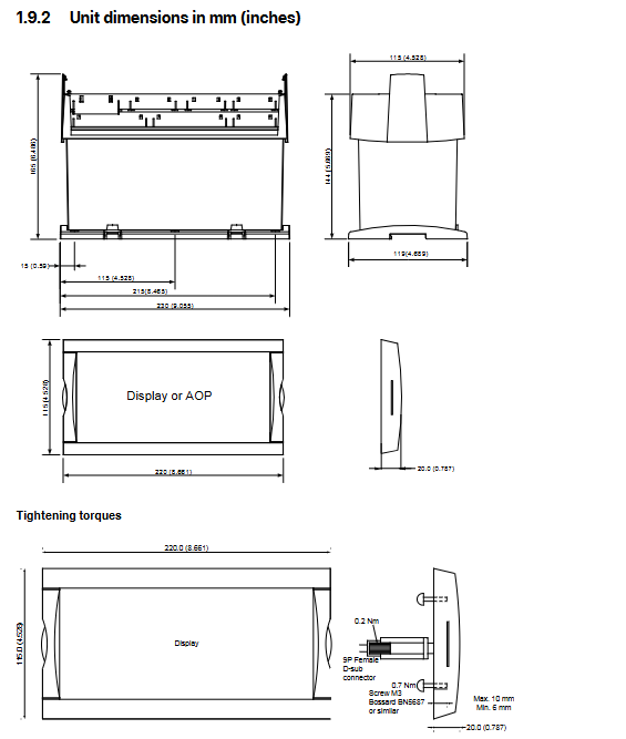
Display configuration: The display unit (DU-2) is independently designed and can be directly installed on the host or at the front end of the distribution cabinet door (with a standard 3m display cable). A single PPU-3 can expand up to 2 additional display units (up to 200m away);
Display content: Real time display of all measured values, calculated values, alarm information, and event logs;
Extended operation panel: Optional AOP-1 (16 configurable LEDs+8 configurable buttons) or AOP-2 (16 configurable LEDs+8 configurable buttons+1 status relay), supporting CAN bus communication.
(2) Regulation Modes
According to the control object (governor/automatic voltage regulator), provide multiple types of switchable standard regulation modes to meet different operational requirements:
Specific functions of control object adjustment mode
Governor maintains a fixed frequency to maintain stable generator output frequency
Fixed power (base load) setting for fixed active power output
Frequency droop automatically adjusts the frequency as the load changes, adapting to parallel load distribution
Load sharing: Balanced allocation of active loads when multiple machines are connected in parallel
Automatic voltage regulator (AVR, optional option D1) with fixed voltage to maintain stable generator output voltage
Fixed reactive power setting for fixed reactive power output
Fixed power factor maintains power factor stability
Reactive load sharing: Balanced allocation of reactive load when multiple machines are connected in parallel
Voltage droop automatically adjusts voltage with changes in reactive load, suitable for parallel scenarios
(3) Self checking and configuration tools
Self test: Perform periodic self tests at startup, display fault information in plain text on the screen, and trigger alarms through relay outputs (status outputs);
M-Logic (Micro PLC): Free integration into PC tool software, supports custom input/output functions and logic conditions, and adapts to personalized application scenarios;
Configuration method:
Local: configured through the password protection menu of the display unit;
Remote: Connect to a PC via USB and use the free Windows version PC tool software (available from the DEIF download center), which supports parameter monitoring, configuration saving/downloading, and firmware updates.
(4) Engine control and protection (optional function)
After installing the engine control and protection module, the PPU-3 can achieve:
Engine start stop sequence control;
Engine protection function: Provides a complete backup of the engine shutdown channel in case of main processor failure, ensuring equipment safety.
(5) CANshare function (optional G9 option)
CANshare provides:
Digital load distribution and line fault (disconnection, short circuit) monitoring;
Support position feedback and monitoring of up to 4 bus circuit breakers (BTBs);
Manage up to 5 load distribution segments;
Monitoring of active/reactive load distribution;
Dead bus closing and first startup discrimination;
Simulation testing mode before debugging.
Standard protection functions (Protections)
PPU-3 is equipped with multiple protection functions that comply with IEEE Std. C37.2-1996 (R2001) standards, covering core fault scenarios of generators and busbars. Some functions support multiple threshold settings:
Protection Function ANSI Number Threshold Order Core Function
Generator reverse power (32) 2nd order to prevent the generator from absorbing grid power (such as when the turbine loses steam)
Generator over current (50/51) 6th order protection of the generator from overload current damage
Voltage dependent overcurrent (51V) 1st order combined with voltage state to determine overcurrent and avoid false triggering
Inverse time over current (51) The larger the first-order current, the shorter the action time, making it suitable for different overload scenarios
Generator over/under voltage (59)/(27) 2nd/3rd order protection for generator insulation and load from overvoltage/undervoltage impact
Generator over/under frequency (81) 3rd/3rd order to prevent frequency deviation caused by abnormal generator speed
Busbar over/undervoltage (59)/(27) 3rd/4th order protection for busbars and downstream loads from overvoltage/undervoltage damage
Busbar over/under frequency (81) 3rd/4th order to maintain bus frequency stability
Busbar voltage imbalance (60) 1st order prevention of equipment failure caused by three-phase voltage imbalance
Generator overload (32) 5th order to avoid long-term operation of the generator beyond rated load
Current/Voltage Imbalance (60) 1st order protection for generators and loads from damage caused by unbalanced current/voltage
Overexcitation/Loss of excitation (40/32 RV) 1st order protection generator excitation system to avoid magnetic field anomalies
Hardware and interface specifications
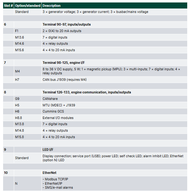
(1) Hardware architecture and slot allocation
The PPU-3 adopts a "slot based" hardware design, with fixed slots corresponding to different functional modules. Each slot only supports one hardware option, and the core slot functions are as follows:
Slot Number Function Category Standard Configuration/Optional Options Core Interface and Parameters
1. Power supply and basic I/O standard 8-36V DC power supply (11W); 1 status output relay; 5 relay outputs; 2 pulse outputs (kWh, kvarh); 5 digit inputs
Communication options include H2 (Modbus RTU/ASCII, RS-485), H3 (Profibus DP), etc., which are responsible for serial communication with external systems such as PLCs
3 load distribution standards with 13 numerical inputs; 4 relay outputs; 1 P (active) load distribution line; 1 Q (reactive power) load distribution line; 2 external set point inputs (GOV/AVR)
4 GOV/AVR/transmitter output standards (4 relay outputs); Optional E1 (2-channel+/-25mA), E2 (2-channel 0 (4) -20mA) and other output control signals can be sent to the speed regulator/AVR, or used as transmitter signal output
5 AC measurement standards, 3 generator voltage inputs; 3-channel generator current input; 3-channel bus/grid voltage input
6 Analog Output Expansion Optional F1 (2-channel 0 (4) -20mA transmitter output) to expand analog output channels
7 engine control and I/O expansion options include M4 (engine control, digital/analog I/O) and H7 (software level engine communication) to achieve engine start stop control, I/O expansion, and specific engine protocol docking
8. Advanced communication and load distribution options include G9 (CANshare), H5 (specific engine protocols such as Caterpillar, MTU), digital load distribution, and engine specific communication protocol docking
9 Ethernet communication options include N (Ethernet TCP/IP, supporting Modbus TCP/IP, EtherNet/IP, SMS/email alarms) to achieve remote monitoring and alarm notification over Ethernet
(2) Key technical parameters
Parameter category specific specifications
Working environment temperature: -25~70 ° C (-25~60 ° C with N option; UL/cUL certified environment maximum 55 ° C); Humidity: 97% RH (IEC 60068-2-30); Altitude: 0-4000m (downgraded for use from 2001 to 4000m)
Measurement range voltage: 100~690V AC (± 20%, UL/cUL certified maximum 600V AC); Current: 1/5A AC (from CT); Frequency: 30~70Hz
Auxiliary power terminal 1-2:12/24V DC nominal (8-36V DC operation, maximum 11W); Terminal 98-99:12/24V DC nominal (8-36V DC operation, maximum 5W); 2A slow melting fuse protection is required
Input/output digital input: optocoupler isolation, 8-36V DC conduction (impedance 4.7k Ω); Analog input: 0 (4) -20mA (impedance 50 Ω) RPM(MPU:2-70V AC,10-10000Hz); Relay output: 250V AC/30V DC (5A, UL/cUL certified 2A resistive load); Analog output: 0 (4) -20mA/± 25mA (isolated, maximum load 500 Ω)
Electrically isolated AC voltage from other I/O: 3250V AC (50Hz, 1min); AC current and other I/O: 2200V AC (50Hz, 1min); Analog output and other I/O: 550V AC (50Hz, 1min)
Protection level host: IP20; Display unit: IP40 (optional L gasket can be upgraded to IP54, required for RS certification applications)
Certified ship certification: certified by all mainstream classification societies; Safety certification: EN 61010-1, UL 508, CSA 22.2 No.14-05; EMC certification: EN 61000-6-2/4, IEC 60255-26
Optional Features and Accessories
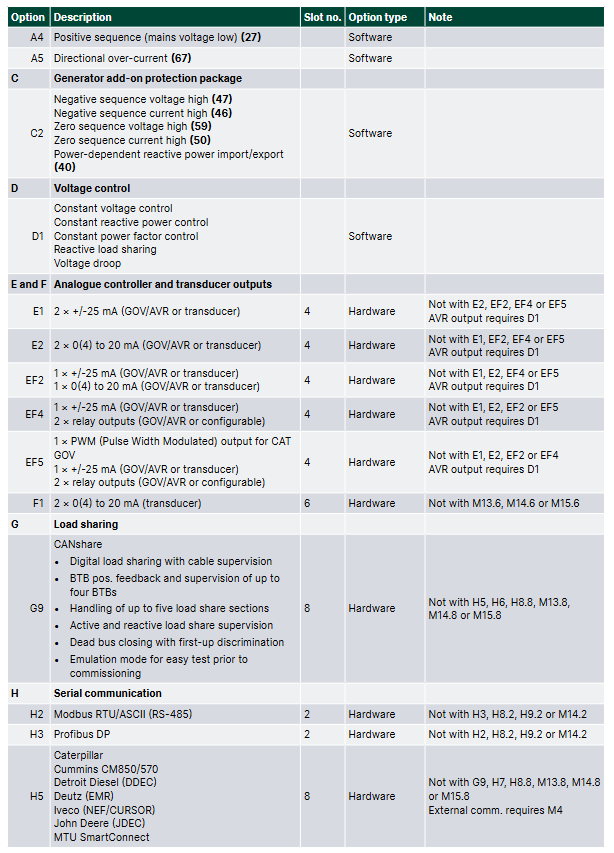
(1) Core optional options (some key options)
Specific description of option code function category
A-series power grid protection package A1 (limited time undervoltage 27t, undervoltage+low reactive power 27Q, etc.), A5 (directional overcurrent 67)
C2 Generator Extended Protection Package Negative Sequence Voltage High 47, Negative Sequence Current High 46, Zero Sequence Voltage High 59, etc
D1 Voltage Control Fixed Voltage, Fixed Reactive Power, Fixed Power Factor, Reactive Load Distribution, Voltage Drop
G9 CANshare digital load distribution+line monitoring, multi BTB monitoring, dead bus closing
H2/H3 serial communication H2 (Modbus RTU/ASCII, RS-485), H3 (Profibus DP)
N Ethernet Modbus TCP/IP, EtherNet/IP, SMS/email alerts
Y1/Y11 display and control Y1 (engine and GB control), Y11 (display unit without local control button)
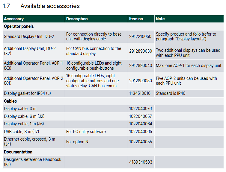
(2) Standard and optional accessories
Accessory type, specific product usage, model/remarks
Display Unit DU-2 (Standard): The host is equipped with Display 2912210050, and the display layout needs to be specified
DU-2 (extension) additional extension display 2912890030, supports CAN bus
AOP-1 expansion operation buttons and LED 2912890040 on the operation panel, with a maximum of one unit per display
AOP-2 expansion panel with status relay 2912890050, up to 5 units per PPU-3
Cable display cable (3m/6m/1m) connects the display unit to the host 1022040076 (3m), 1022040057 (6m), etc
USB cable (3m) PC configuration connection 1022040065
Cross Ethernet cable (3m) N option Ethernet connection 1022040055
IP54 display gasket (L) enhances the protection level of the display unit 1134510010, required for RS certification
Ordering and Disclaimer
(1) Order specifications
Required information: model (such as PPU-3 Marine), variant number (such as 01 with display/07 without display), product number (such as 2912210030-01);
Optional information: Please specify the selected functional options (such as M4, Y1, H2) and accessories (such as AOP-2, IP54 gasket);
Example: Product number 2912210030-01 (PPU-3 Marine 01 with display)+option M4 (engine control)+Y1 (engine and GB control)+H2 (Modbus RTU).
(2) Disclaimer
DEIF reserves the right to modify document content without prior notice;
The English version of the document is the latest authoritative version, and there may be delays in the translated version. In case of any conflicts, the English version shall prevail;
DEIF is not responsible for the accuracy of the translated version.
- YOKOGAWA
- Reliance
- ADVANCED
- SEW
- ProSoft
- WATLOW
- Kongsberg
- FANUC
- VSD
- DCS
- PLC
- man-machine
- Covid-19
- Energy and Gender
- Energy Access
- Renewable Integration
- Energy Subsidies
- Energy and Water
- Net zero emission
- Energy Security
- Critical Minerals
- A-B
- petroleum
- Mine scale
- Sewage treatment
- cement
- architecture
- Industrial information
- New energy
- Automobile market
- electricity
- Construction site
- HIMA
- ABB
- Rockwell
- Schneider Modicon
- Siemens
- xYCOM
- Yaskawa
- Woodward
- BOSCH Rexroth
- MOOG
- General Electric
- American NI
- Rolls-Royce
- CTI
- Honeywell
- EMERSON
- MAN
- GE
- TRICONEX
- Control Wave
- ALSTOM
- AMAT
- STUDER
- KONGSBERG
- MOTOROLA
- DANAHER MOTION
- Bentley
- Galil
- EATON
- MOLEX
- Triconex
- DEIF
- B&W
- ZYGO
- Aerotech
- DANFOSS
- KOLLMORGEN
- Beijer
- Endress+Hauser
- schneider
- Foxboro
- KB
- REXROTH
- YAMAHA
- Johnson
- Westinghouse
- WAGO
- TOSHIBA
- TEKTRONIX
- BENDER
- BMCM
- SMC
- HITACHI
- HIRSCHMANN
- XP POWER
- Baldor
- Meggitt
- SHINKAWA
- Other Brands
- UniOP
- KUKA
- IBA
-
Woodward 8272-796 - Real Power Sensor Module 115/230v-ac
-
Woodward 5463-873 - NetCon Output Module
-
Woodward 8271-567 - Load Sensor Module 120/208v-ac
-
Woodward Type UG-8 P/N 8522-300 EG - Governor R.P.M 1075-1650 With Motor Groschopp
-
WOODWARD 9905-971 REV J - LINKNET 16 CHANNEL DISCRETE INPUT MODULE
-
WOODWARD 8280-3014 - 723 PLUS DIGITAL CONTROL REV NEW
-
Woodward 505DE - Digital Control System
-
Woodward 5453-750 - Ethernet Interface FTM
-
Woodward 9907-018 Rev H - 2301A Load Sharing & Speed Control
-
WOODWARD 5420-1080 V4.3 - BOARD-PPA WITHBOX
-
Woodward b 8271-347SP - 2301 speed control
-
Woodward 9905-795 Rev B - Digital Synchronizer and Load Control
-
Woodward 9905-377 Rev. A - 2301A Load Sharing and Speed Control
-
WOODWARD 8272-582 - Generator speed control module
-
WOODWARD 9907-247 REV K - 828 DIGITAL CONTROL UNIT
-
WOODWARD 5466-353 REV C - NETCON MAIN CHASSIS TRANSCEIVER
-
Woodward Type UG-8 P/N 8524-708 - Governor 760-1560 Governor R.P.M
-
WOODWARD 9907-247 REV K - 828 DIGITAL CONTROL UNIT
-
WOODWARD 8440-1831 REV. H - EASYGEN3000 3200-5 - WITHOUT ACCESSORIES
-
WOODWARD 8444-1002 REV G - UMT1 MEASURING TRANSDUCERS
-
Woodward 5410-312C - Digital Marine Control Printed Circuit Board
-
Woodward 9905-799 REV F - Digital Synchronizer & Load Control , V#456
-
Woodward 9907-014 - 2301A for controller
-
Woodward Type UG-8 P/N B522-446 - Governor R.P.M 500-1200
-
WOODWARD 8272-221 REV.B - DIGITAL REFERENCE UNIT
-
Woodward 8901-037 - Booster Servomotor Single
-
WOODWARD 8444-1019 REV G - UMT 1 MEASURING TRANSDUCER
-
WOODWARD 1767-367 Z21 WK 0920702 - GOVERNOR MOTOR 2700 RPM KM 58-20 K 230V
-
WOODWARD 9905-972 Rev:G - LINKNET 6 CHANNEL 4-20mA OutPut
-
Woodward E8250-501 - Actuator Governor
-
LTI Drives CDF30.002.C0.7 Compact Servo Controller 08685963 DC 24V Industrial Module
-
LUST LTI Drives CDB32.008.W2.4.BR.PC1 Servo Drive Industrial Motion System
-
LUST LTI Drives CDB34.003.C2.4.PC1.H15 Servo Motor Driver Industrial Control Unit
-
LUST LTI Drives CDA32.004.C1.4.H08.B0 Servo Drive Mat. 3084456 Industrial Control
-
LUST LTI Drives CDE34.005.W2.2 Industrial Servo Drive Motion Control Unit
-
LUST LTI Drives CDA34.006.W3.0 Servo Drive Software V3.70-04 Industrial Controller
-
LTI Drives CDB32.004.C2.4.SH Servo Drive Compact Motion Controller
-
Woodward 9905-373 - Digital Synchronizer And Load Controller
-
WOODWARD MAGNETIC PICKUPS - Sensor
-
WOODWARD GCP-30 - Steuertafel for Industrial Regulator Genset Control Package
-
WOODWARD GOVERNOR 9907-1183 REV A - 505 ENHANCED TURBINE CONTROL
-
WOODWARD 9907-173 REV B - Module Load Sharing 120 Volt
-
WOODWARD 9907-014 - 2301A controller
-
Woodward 9905-029 - SPM-A Synchronizer Module Rev C
-
WOODWARD 8440-1799 EASYGEN-350 REV B - Genset Controller
-
WOODWARD 5466-258 REV M - SIMPLEX DISCRETE I/O MODULE
-
Woodward 8440-1884 C - Controller Easygen 2500-5
-
Woodward 8441-1153 - Monitoring Unit 250VAC
-
WOODWARD 8406-120 REV G - EGCP-2 DIGITAL CONTROL
-
Woodward 8273-584 - Atlas-ii Digital Control
-
Woodward 8272-582 - APM Motor Control 8272582
-
Woodward 9905-377 Rev. A - 2301A Load Sharing and Speed Control
-
WOODWARD 8272-517 - Pm Motor Control
-
WOODWARD 9905-797 REV.B - DIGITAL SYNCHRONIZER AND LOAD CONTROL DSLC-D
-
WOODWARD 8272-582 - APM MOTOR CONTROL
-
Woodward Seg FP2-8-24 - Emergency Power Telecommunications Module NP2
-
WOODWARD 2001-12E2U1B1S1A - Fuel Shut Off Valve Stop Solenoid Valve 2000-4505
-
Woodward 8440-1884 K - Genset Controller Easygen-2500-5
-
Woodward 9905-760 - Linknet Termination Module
-
Woodward 8404-009 - Proact Digital Plus Front Panel Rev. H
-
Woodward 8271-651 - Digital Speed Reference
-
Woodward 3077-474C - 8605895 5501-031 D Circuit Module
-
WOODWARD 5466-257 REV.-C - NETCON 5000 MODEL REMOTE TRANSCEIVER I/O MODULE
-
Woodward 8273-101 Rev: A - 2301D Digital Load Sharing and Speed Control
-
WOODWARD 8272-799 - 2301A SPEED CONTROL WITH REMOTE REFERENCE REV:C
-
Woodward 8272-517 - PM Motor Control
-
Woodward 8290-048 8290048 Rev. F - Generator Load Sensor
-
woodward 8273-1012 rev c - 2301e Load Sharing and Speed Control
-
WOODWARD 9905-797 - DIGITAL SYNCHRONIZER AND LOAD CONTROL FOR 3 PHASE GENERATORS
-
WOODWARD 8280-3014 - 723 PLUS DIGITAL CONTROL REV NEW
-
WOODWARD 8440-1884 REV G - GENSET CONTROLLER EASYGEN-2500-5/P1
-
Woodward 8272-683 K - Digital Reference
-
WOODWARD 9907-014 - SPEED CONTROL 2301A REV H
-
Woodward Type UG-8 P/N 037260 - Governor R.P.M 1075-1650 Motor KM58-20
-
WOODWARD 9905-970 - LINKNET 6 CHANNEL 100 OHM RTD Rev:J
-
Woodward 9907-1183 Rev C - Steam Turbine Digital SCREEN 505E Turbine Control
-
Woodward 8440-1614 - GCP-30 Genset Control Package, Rev: F, Type 1, E231544
-
Woodward DC11006-304-024 - ACTUOTOR DYNA ACTUATOR - BARBER-COLMAN
-
Woodward 9905-971 - LINKNET 6 CHANNEL 100 OHM RTD Rev:K
-
Woodward DYNK-10249 - Actuator Controller Kit - DYNA 2000
-
Woodward LR21035 - MFR1 MULTI FUNCTION RELAY REV F
-
Woodward 8440-1831 - EASYGEN 3200-5 P/N: REV. G Gererator Controller
-
Woodward 8272-516 - PM MOTOR CONTROL REV J
-
Woodward 8440-2080 - EASYGEN 2000 genset controller EASYGEN-2300-5/P1
-
Woodward 505DE - Digital Control System
-
Woodward 701 - Digital Speed Control 18-40 VDC 4-20 MA
-
Woodward 8440-1799 - EASYGEN-350 REV B
-
Woodward 8272-582 - Apm Motor Control 100-220v AC/DC
-
Woodward 5501-031 D - 3077-474C 8605895 Circuit Module
-
Woodward XD1-T - XD1T55SAT TRANSFORMER DIFFERENTIAL PROTECTION RELAY
-
Woodward 8272-517 - PM Motor Control 220vac
-
Woodward 8934-658 - Repair Kit UG8D Governor
-
Woodward 5437 18 - module netcon derivative analog rev.A
-
Woodward 8272-171 A - Pm Motor Control
-
Woodward MRN3-1/2 - SEG mains uncoupling relay MRN314D mains decoupling relay
-
Woodward 9905-373 - Digital Synchronizer and Load Control 18-40 VDC Rev P
-
Woodward 5431-640 C - Dual Dynamics 1000 Series Speed Control Module
-
Woodward 5501-031 D - 3077-474C 8605895 Circuit Module
-
Woodward 9907-247 - 828 DIGITAL CONTROL
-
Woodward 8440-1855-G - EASYGEN-2200-5 /P1 12/24VDC GENSET CONTROLLER
-
Woodward NC3-2-8 (NO) - GENERATOR CONTROLLER
-
Woodward 8271-467 K - 2301 LOAD SHARING AND SPEED CONTROL PART NO:
-
Woodward 8440-2177 A - SPM-D2-10 Digital Synchronising Controller
-
Woodward LXMG1614E-14-11 - CCFL and UV Lamps Inverter Module
-
Woodward 8270-990 - signal converter
-
Woodward 9905-068 - LOW VOLTAGE 2301A LOAD SHARING & SPEED CONTOL P/N:
-
Woodward 8901-051 - BOOSTER SERVOMOTOR, SINGLE CYLINDER, 2:1
-
Woodward 8444-1024 D - MWS4-55M CONTROL MODULE UNIT
-
Woodward 5448-914 - GCP-20 Genset Control GCP-20 REV D P/n:
-
Danfoss BHA-1 018-1942 - Hydraulic Actuator
-
Woodward 9905-001 L - SPM-A SYNCHRONIZER
-
Woodward 5464-850 - Module
-
Woodward 5501-371 - Micronet Simplex Mpu Aio Rev C
-
Woodward 8272-132 B - POWER SENSOR
-
Woodward 9907-028 - SPM-A Synchronizer
-
Woodward SA-3678-AM-2 - Overspeed Electric Governor, Model ESSE2-AM
-
Woodward E8250-502 - GOVERNOR ACTUATOR
-
Woodward 8440-1884 J - Controller EASYGEN-2500-5
-
Woodward 5441-693 - DIGITAL I/O MODULE -MISSING PART
-
Woodward SA-4450 - Speed Controller APECS 3100 For Magnetic Pickup
-
Woodward 9903-466 - 701 DIGITAL SPEED CONTROL REV G
-
Woodward 1765-843 - Governor Speed Adjusting Motor P/N Type: SMM40 220V AC 50/60Hz
-
Woodward 9905-760 - Linknet Termination Module
-
Woodward 9907-247 - 828 DIGITAL CONTROL UNIT REV K
-
Woodward 5484-721 - motor
-
Woodward 8440-1734 - MFR-2 Rev.A Multi Function Relay MFR-2
-
Woodward CSC3SUWA - Controller
-
Woodward 8440-1667 - REV B SPM-D1010B/XN

K-JIANG

Add: Jimei North Road, Jimei District, Xiamen, Fujian, China
Tell:+86-15305925923