
K-WANG


ABB PCS6000 SYSTEM DRIVES
ABB PCS6000 SYSTEM DRIVES
Safety regulations and operating guidelines
1. Safety standards and warning signs
Adhere to standards: The manual strictly follows international standards such as ANSI Z535.6 (Safety Information Standard), ISO 3864-2 (Safety Label Design), EN 50110 (Electrical Safety Code), etc., to ensure the safety of equipment during design, installation, and operation.
Warning label classification:
DANGER: Refers to a dangerous situation that, if not avoided, could result in death or serious injury (such as high-voltage electric shock).
Warning: Potential risk of serious injury or equipment damage (such as high temperature surfaces, mechanical compression).
CAUTION: Possible situations that may cause minor injury or equipment malfunction (such as electrostatic discharge, misoperation).
Notice: Non safety related but important operating precautions (such as dust accumulation affecting equipment performance).
Special warning: The electromagnetic field generated during equipment operation may interfere with pacemakers. Warning signs should be marked near the equipment to restrict access by relevant personnel.
2. Seven step safety operation process
To prevent electric shock and arc damage during electrical operations, the manual defines a strict "seven step life-saving principle":
Homework preparation: Conduct on-site risk assessment, confirm work permit, and equip appropriate personal protective equipment (PPE, such as insulated gloves and arc protective clothing).
Equipment identification: Confirm the equipment status through visual and auditory inspection, set up physical isolation barriers to avoid interference from unrelated personnel.
Power off locking (LOTO): Disconnect all energy supplies, use locks and labels to prevent accidental closing, and implement group LOTO for multi person operations.
Voltage detection: Use qualified voltage detection equipment to verify that there is no voltage after power failure, and calibrate the equipment on a known power source before and after the detection.
Grounding and short circuit: Close the grounding switch or use a portable grounding device to ensure safe discharge of fault current.
Protection of adjacent live parts: Maintain a safe distance, use insulated shielding tools, and avoid contact with exposed conductors.
License confirmation: Check the isolation points and grounding status to ensure that all operators understand the risks before signing the license document.
3. Safety requirements for main circuit breakers (MCBs)
Functional positioning: MCB is the core protection device of the frequency converter, which needs to quickly cut off the main power supply in case of a fault to prevent personnel injury and equipment damage.
Technical parameters:
Breaking time: Protection tripping time ≤ 75 ms (to limit equipment damage), safety tripping time ≤ 500 ms (to ensure personnel safety).
Control mode: The MCB disconnection command needs to come directly from the frequency converter. If it is transferred through PLC/DCS, the system needs to pass SIL 3 certification, and the use of local remote switch interruption disconnection commands is prohibited.
Redundant design: It is recommended to equip with dual independent trip coils or undervoltage coils, combined with the "Circuit Breaker Failure Protection (ANSI 50BF)" function of the upstream circuit breaker, to ensure reliable disconnection in case of a fault.
Product Architecture and Modular Design
1. Application scenarios and configuration selection
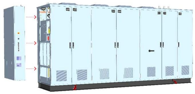
Core application: PCS6000 is a medium voltage frequency converter (3.3 kV level) designed specifically for large wind turbines and tidal energy equipment, supporting full power conversion and suitable for grid connected and off grid applications.
Topology structure:
1CL (single conversion line): Compact structure, suitable for conventional working conditions.
2CL (Dual Conversion Line): Supports "Restricted Mode", which allows for single line operation when one line fails, improving system availability and reducing downtime.
2. Detailed explanation of modular components
(1) Power Unit (POU)
Function: Implement AC-DC-AC conversion of electrical energy, including three 3-level neutral point clamp (NPC) phase bridge arms, using integrated gate commutated thyristors (IGCT), supporting high voltage and high current operating conditions.
Design features:
Semiconductor devices are integrated into a single stacked structure to improve heat dissipation efficiency.
The main circuit interface board is responsible for controlling signal processing and status monitoring, and supports real-time fault diagnosis.
(2) DC Link Unit (DLU)
Core module:
Neutral Connection Module (NCM): Grounding the neutral point through an RC network, limiting the rate of change in ground voltage (dv/dt), allowing for short-term operation under single ground faults, and rapid shutdown after fault detection.
Voltage limiting module (VLM): When the DC link voltage exceeds the threshold, energy is released through the braking resistor, and the capacitor is discharged during shutdown to ensure maintenance safety.
Dv/dt filtering module (VFM): suppresses high-frequency oscillations generated by IGCT switches, protects transformer and generator windings, and reduces electromagnetic interference (EMI).
Generator Isolation Switch Module (GDM): Three position electric isolation switch (closed/open/grounded), supports manual operation (equipped with a rotating handle), isolates the generator in case of a fault.
(3) Grid Circuit Breaker Unit (GBU)
Function integration:
Circuit breaker: It realizes the on/off and short-circuit protection of the grid side circuit, and supports vacuum circuit breakers or SF ₆ circuit breakers.
Three position switch: including "connection", "test", and "grounding" positions. When grounding, it is necessary to operate under zero current to ensure personnel safety.
Operation method: Manually operated by hand crank, equipped with mechanical interlocking to prevent misoperation.
(4) Other key units
Water cooling unit (WCU): maintains constant water temperature (≥ 0 ° C) and flow rate, supports external heat exchanger connection, built-in ion exchanger purifies cooling medium, and pump set supports soft start to reduce impact.
Filter Unit (FIU): It includes a High Pass Filter Module (HFM) and a Filter Reactor Module (FRM), which meet the harmonic limit standards of the power grid (such as IEC 61000-3-6).
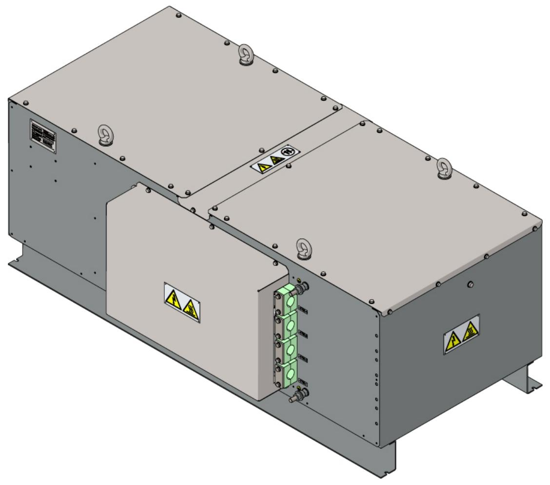
Braking Resistance Unit (BRU): Modular design, supports roof installation, maximum cable length of 10 meters, monitors heat dissipation through temperature models, optional BRU51/52/72 models, thermal capacity 7.5-15 MJ.
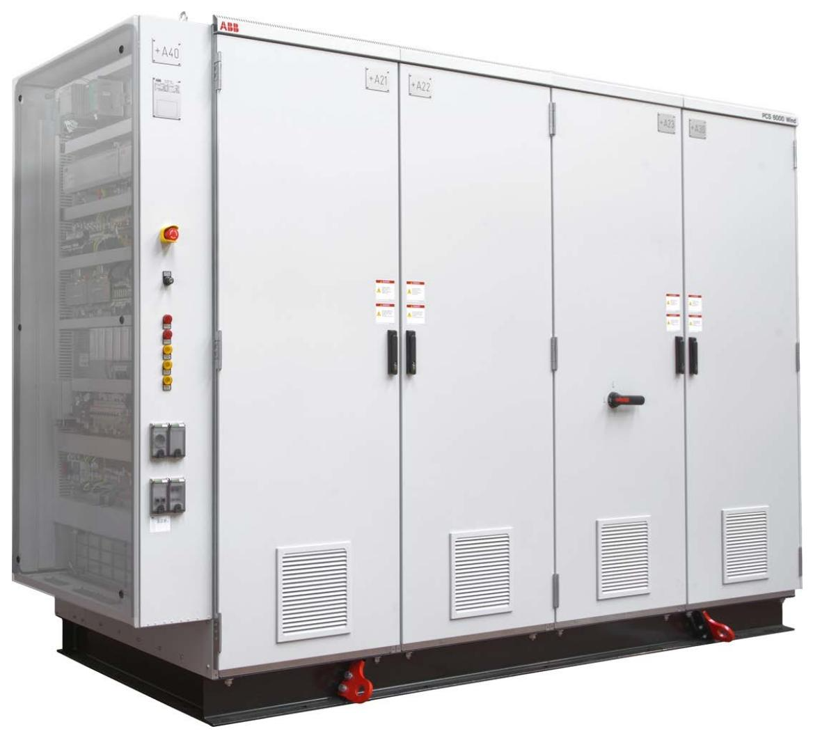
3. Cabinet design and protection
Mechanical structure:
Galvanized steel frame+1.5mm powder coated steel plate, protection level IP54, resistant to dust and water spray.
Modular design supports back-to-back and series layout, saving installation space and suitable for narrow environments such as wind turbine cabins.
Electromagnetic compatibility (EMC):
The cabinet doors and side panels are sealed with conductive gaskets, and the internal panels are not painted to enhance the metal grounding effect.
The cable entry is equipped with EMC shielding strips to ensure that radio frequency interference (RFI) suppression complies with EN 61000-6-4 standard.
Environmental adaptability:
Working temperature: -10 ° C~+40 ° C (when the water cooling system is running), storage temperature: -25 ° C~+55 ° C.
Vibration protection: Compliant with IEC 60068-2-6 standard, suitable for the vibration environment of wind turbines.
Installation and commissioning process
1. Transportation and Storage Standards
Packaging requirements:
Land transportation: Wooden pallets (thickness 5 cm, length and width exceeding the cabinet by 30/60 cm)+polyethylene film (0.12 mm thickness), fixed with a winding machine applying 20-38 units of tension.
Sea freight: wooden box+aluminum foil moisture-proof film (three-layer structure, middle layer aluminum foil isolates water vapor), desiccant (in accordance with DIN 55474) placed inside, humidity indicator monitors environmental humidity.
Precautions for handling:
Using a crane or forklift, it is prohibited to directly lift the top of the cabinet, and force must be applied through the bottom lifting ring.
The fork distance of the forklift should be greater than 1500 mm, and the driving speed should be limited to walking speed to avoid tilting more than 30 degrees.
2. Mechanical and electrical installation
(1) Mechanical installation
Basic requirements: The cabinet is fixed to the horizontal floor with M16 bolts, and the bottom sealing plate can serve as a water collection tray to prevent internal water leakage from spreading.
Environmental control: The installation area should be dust-free, and the equipment should be covered with plastic sheeting during construction to prevent dust from entering; Paint damage needs to be repaired with polyurethane coating to ensure anti-corrosion and insulation performance.
(2) Electrical installation
EMC cabling principles:
Cable classification:
Class 1: Sensitive signals (such as 4-20 mA analog signals) require twisted pair shielding, with both ends of the shielding layer grounded.
Class 4: High interference lines (such as motor start stop signals), with a distance of ≥ 600 mm from other cables, laid vertically when crossing.
Shielding grounding: The shielding layer of the power cable needs to be connected to the grounding busbar near the frequency converter. If the cross-sectional area of the shielding layer is less than 50% of the phase conductor, equipotential bonding wires need to be laid in parallel.
High voltage connection:
Using Pfister ® PLUG P3 series connectors (such as P3SC straight type, P3EC1/2 curved type), code AF01 to ensure correct pairing, cable cross-sectional area of 70-240 mm ², maximum length of 150 m (grid side)/100 m (generator side).
When connecting, ensure that the plug is aligned with the socket and the torque meets the manufacturer's requirements to avoid overheating caused by poor contact.
(3) Grounding system
Protective grounding (PE): The cabinet is connected to the main grounding grid through bottom M12 bolts, and the cross-sectional area of the grounding conductor is ≥ 95 mm ² (calculated based on a fault current of 16.2 kA and a breaking time of 0.5 seconds).
Functional grounding (FE): Used to discharge the common mode current generated by switch devices, separated from PE, and connected through an independent grounding bar to ensure EMC performance.
3. Debugging and Startup
prerequisite:
Complete mechanical alignment, bolt tightening, and cooling system water injection (deionized water+ethylene glycol).
The electrical connection is correct and the insulation test is qualified (the insulation resistance of cables, transformers, and generators meets the specifications).
Anti exposure activation sequence:
When the device is powered off for a long time and restarted, the control unit heater needs to be started first. When the internal temperature is ≥ 5 ° C and there is no condensation, the water-cooled pump is started for circulating heating. The entire process may last for 12 hours (in a low-temperature environment).
Pre startup inspection:
Confirm that all cabinet doors are closed, door lock switches are functioning properly, and there are no fault alarms (such as when the DC link grounding switch is in the "ungrounded" position and the LED indicator light is off).
Set the key switch to "ON", the auxiliary power supply (3AC 400V/24VDC) is supplying power normally, and the pressure and flow rate of the water cooling system meet the standards.
Operation and Maintenance Guide
1. Daily operation interface
Local control device (located on the side of CCU):
Emergency stop button: Immediately disconnect the MCB after pressing, block the IGCT pulse, discharge the DC link through VLM, manually reset and clear the fault before recovery.
Key switch: controls the "start disable" or "local/remote" mode switching to prevent unauthorized operation.
Status indicator light: displays grid/generator voltage, grounding status, DC link status, etc. For example, if the "ISOLATOR CLOSED" light is on, it indicates that the DC link has been grounded and can be safely maintained.
Remote control: Connected to the higher-level control system through fieldbus (such as Profibus, Ethernet), supporting real-time monitoring of parameters such as voltage, current, temperature, etc., receiving start stop commands and fault alarms.
2. Maintenance strategy and cycle
Preventive Maintenance Plan (Refer to PCS6000 Preventive Maintenance Plan 3BHS600000 E88):
Daily: Check the operating status, cooling system leaks, and whether there are any abnormal noises or odors.
Quarter: Clean the dust inside the cabinet (blow with compressed air, avoid using damp cloth), check the tightness of bolts and cable wear.
Year: Test MCB trip circuit, insulation resistance, grounding resistance, replace aging components (such as capacitors and fans), and record maintenance logs.
Key maintenance tasks:
Water cooling system: Replace ion exchange resin annually, check the conductivity of the coolant (≤ 5 μ S/cm), and clean the surface dirt of the heat exchanger.
IGCT inspection: Dynamic testing is conducted every two years to confirm that the switch characteristics meet the factory standards and avoid faults caused by device aging.
3. Fault diagnosis and handling
Fault classification:
Alarm: Do not interrupt operation. If the cooling water temperature is too high or the fan fails, the cause should be promptly investigated.
Fault: Forced shutdown, such as overvoltage, short circuit, IGCT fault, should be reset and repaired according to the "Fault Manual" (Appendix A09).
Processing procedure:
Record fault code: Obtain fault information through remote interface or local display screen, such as "F001: DC Link Overvoltage".
Preliminary investigation: Check the power supply voltage, brake resistor connection, VLM function, and confirm whether it is caused by power grid fluctuations or sudden load changes.
Professional maintenance: If it is a hardware failure (such as capacitor rupture, IGCT damage), ABB authorized personnel must replace the components. Non professionals are prohibited from disassembling high-voltage components.
Spare parts management: Key spare parts (such as IGCT and control board) need to be stored in anti-static packaging, with a storage environment temperature of 5 ° C~40 ° C and humidity ≤ 60%.
Documentation and Compliance
1. Supporting documents
Manual and drawings:
PCS6000 Service Manual (3BHS600000 E80): Detailed disassembly steps and component replacement guide.
EMC and Grounding Plan (3BHS856856 E62): Guide cable layout and grounding system design.
Electrical Drawings (Appendix A03): Includes schematic diagrams, wiring diagrams, and terminal block definitions.
Electronic documents: USB storage devices are provided with the device, including interface files, firmware upgrade programs, and fault diagnosis tools.
2. Compliance and Certification
Safety certification: CE certification (compliant with Low Voltage Directive, EMC Directive), some markets require UL/cUL, T Ü V and other certifications.
Standard compliance:
EMC: The emission limit complies with EN 61000-6-4, and the immunity complies with EN 61000-6-2.
Environment: RoHS Directive (Restriction of Hazardous Substance Use), WEEE Directive (Waste Management Requirements).
Summary
The ABB PCS6000 user manual focuses on safety and ensures the reliable operation of medium voltage inverters in the field of renewable energy through modular design, strict installation procedures, and full lifecycle maintenance strategies. Users need to strictly follow the safety regulations in the manual, combined with professional training and regular maintenance, to maximize the energy efficiency and service life of the equipment. If further support is needed, technical support and spare parts supply can be obtained through ABB's global service network.
- YOKOGAWA
- Reliance
- ADVANCED
- SEW
- ProSoft
- WATLOW
- Kongsberg
- FANUC
- VSD
- DCS
- PLC
- man-machine
- Covid-19
- Energy and Gender
- Energy Access
- Renewable Integration
- Energy Subsidies
- Energy and Water
- Net zero emission
- Energy Security
- Critical Minerals
- A-B
- petroleum
- Mine scale
- Sewage treatment
- cement
- architecture
- Industrial information
- New energy
- Automobile market
- electricity
- Construction site
- HIMA
- ABB
- Rockwell
- Schneider Modicon
- Siemens
- xYCOM
- Yaskawa
- Woodward
- BOSCH Rexroth
- MOOG
- General Electric
- American NI
- Rolls-Royce
- CTI
- Honeywell
- EMERSON
- MAN
- GE
- TRICONEX
- Control Wave
- ALSTOM
- AMAT
- STUDER
- KONGSBERG
- MOTOROLA
- DANAHER MOTION
- Bentley
- Galil
- EATON
- MOLEX
- Triconex
- DEIF
- B&W
- ZYGO
- Aerotech
- DANFOSS
- KOLLMORGEN
- Beijer
- Endress+Hauser
- schneider
- Foxboro
- KB
- REXROTH
- YAMAHA
- Johnson
- Westinghouse
- WAGO
- TOSHIBA
- TEKTRONIX
- BENDER
- BMCM
- SMC
- HITACHI
- HIRSCHMANN
- XP POWER
- Baldor
- Meggitt
- SHINKAWA
- Other Brands
- UniOP
- KUKA
- IBA
- Beckhoff
- ADLINK
-
ADLINK HPCI-14S12U - Industrial Control Backplane 12PCI Backplane PCI-14S Passive Backplane
-
ADLINK PCIe-GIE74C - image acquisition card 4-CH GigE Vision PoE+ Frame Grabber
-
ADLINK PCI-8164 - control card 4-Axis Advanced Motion Controller Board
-
ADLINK PCIe-U304 - 4 Port USB3 PCIe Frame Grabbers USB Screw Hole Card
-
ADLINK PCI-9112 - Multi-Function Data Acquisition Card DAQ Card
-
ADLINK PCI-7432 - 51-12013-0A50 4-CH Isolated Numérique I/O PCI Cartes Digital I/O Card
-
ADLINK PCA-6106P3-0C1 REV.C1 - backplane 6-Slot Passive Backplane Board
-
ADLINK PCI-7224 - 24-CH Opto-Isolated Digital I/O PCI Board
-
ADLINK CPCI-7433R(G) - Digital Input Board Rear I/O CompactPCI Card
-
ADLINK EBP-13E4 - 51-46703-0A30 Industrial PC Backplane Passive Backplane
-
ADLINK PCIE-HDV62 - Image acquisition card High Definition Video Frame Grabber
-
ADLINK EBP-13E4 - 51-46703-0A30 Industrial Backplane Board Passive Backplane
-
ADLINK 90111-B1 / CPCI-6770 - PCB CPU MODULE CompactPCI Single Board Computer
-
ADLINK PCI-7248 - DATA ACQUISITION PCI CARD 48-CH Parallel Digital I/O Board
-
ADLINK PCI-7230 - 51-12003-0a50 board PCI7230 32-CH Isolated Digital I/O Card
-
ADLINK PCI2A000CB - 51-20000-0B30 Multi-Function DAQ Card Baseboard
-
ADLINK PCI-8134-005 - 4-Axis Motion Controller Card
-
ADLINK PCI-7224 - 24-CH Opto-Isolated Digital I/O PCI Card
-
ADLINK PCI-7434 - 64-CH Isolated Digital Output Card
-
ADLINK PCI-8132 - motion control card 2-Axis Servo & Stepper Controller
-
ADLINK PCI-8134 - Motion Controller PCI Card 4-Axis Controller Board
-
ADLINK PCI-8164 - Motion Control Card 51-12406-0A40 4-Axis Controller
-
ADLINK 51-12001-0C20 - Circuit Board Data Acquisition Interface Module Hardware
-
ADLINK NuPR0-840 - industrial control motherboard Full-Size PICMG CPU Board
-
ADLINK PCI-7444 - 51-12023-0A10 card 128-CH Isolated Digital Output Board
-
ADLINK PCI-1612B - data acquisition card 4-Port RS-232/422/485 Serial Communication Card
-
ADLINK PCI-6208V 009 - 8/16-CH 16-Bit Analog Output Cards PCB-I-E-482=6BX3
-
ADLINK NUPRO-935A/LV - industrial control motherboard Full-Size PICMG SBC Board
-
ADLINK PCI-9114DG - Multi-Function DAQ Card Data Acquisition PCI Card
-
ADLINK ACL-7130 - Data acquisition card Isolated Digital I/O Board
-
ADLINK ABX-6300D-4E1-BP - board ABX6300D4E1BP Video Interface Expansion Card
-
ADLINK CPCI-6940 - CPCI-6940/D1539/M16-0(EA)-000E 6U CompactPCI Processor Board
-
ADLINK NuPRO-760 - industrial control motherboard Half-Size PICMG SBC CPU Board
-
ADLINK IMB-M42H (G)-0020 - industrial control motherboard LGA1155 Micro-ATX Mainboard
-
ADLINK RTV-24 / PCI-MP4S - 51-12519-1C30 4-Channel Real Time Video Capture Board
-
ADLINK PCI-8134 - 4-Axis Servo & Stepper Motion Controller Card
-
ADLINK MXC-6101D - V.PC000.002.ST.00 Box PC Configurable Embedded Computer
-
ADLINK PCI-8134A - 51-12421-0A10 Motion Control Card 4-Axis Controller Card
-
ADLINK DIN-100S / DIN-100SA1 - Technology SCSI-II TB 100-PIN Terminal Block Board
-
ADLINK DIN-812M001 / DIN812M001 - 51-14034-0A1 51140340A1 Terminal Module Breakout Interface
-
ADLINK PCI-8164 - Servo motion control 4-Axis Advanced Controller Card
-
ADLINK PCIe-GIE64 - Acquisition card GigE Vision PoE+ Frame Grabber
-
ADLINK M-302 - Industrial control motherboard ATX PC Board Mainboard
-
ADLINK PCI-8134 - Motion Controller PCI Card 4-Axis Controller Board
-
ADLINK PCI-RTV24 - Image capture card Analog Video Frame Grabber
-
ADLINK PCI-8102 - Motion control card 2-Axis Servo & Stepper Controller Board
-
ADLINK PCI-9112 REV.B1 - Card Multi-Function Data Acquisition Card
-
ADLINK HSI-DI32-M-N / HSL-TB32-M-DIN - Discrete I/O MODULE Distributed Automation Module System
-
ADLINK PCI-7296 - IO card REV.A3 96-CH Parallel Digital I/O Card
-
ADLINK DIN-814P-A4 / 814Y - terminal board Motion Control Interface Block
-
ADLINK DIN-814P-A4 - 51-14056-0A10 PCB-I-E-2736=ZA01 Screw Terminal Board Breakout
-
ADLINK M-322 - motherboard Industrial Control Computer Mainboard
-
ADLINK NUPRO-406 REV:B1 - industrial control motherboard Full-Size PICMG CPU Board
-
ADLINK AMP-204C - card DSP-Based 4-Axis Advanced Pulse-Train Controller
-
ADLINK HPCI14S REV.B1 - industrial computer baseboard 14-Slot Passive Backplane
-
ADLINK PCI-7250 - 8-CH Relay Output & 8-CH Isolated DI PCI Card
-
ADLINK EBP-13E2 - baseplate Passive Backplane Industrial Computer Chassis Board
-
ADLINK LPCI-3488A - PCI-GPIB card 51-12801-0A30 acquisition card IEEE-488 Interface Board
-
ADLINK PCI-6216V-GL - 51-12201-0C30 16-CH 16-Bit Voltage Analog Output Card
-
ADLINK ACL-8454 - 16-CH Isolated Digital I/O & 4-CH Counter Card
-
ADLINK HPCI-9S7U - backplane Passive Backplane Compatible with NuPRO-A301 852 841 842
-
ADLINK DAQ-2010-007 - Simultaneous-Sampling Multi-Function Data Acquisition Card
-
ADLINK MP-C154 - 51-64205-0A10 Motion Control Card 4-Axis Controller Board
-
ADLINK MXE-202/mSSD16B/WiFi-BT - Matrix Rugged I/O Platform Embedded Fanless Computer
-
ADLINK CM-920-R-17 - PC/104-Plus Single Board Computer Module Intel Celeron M
-
ADLINK PCI-7250 NSMP - 8-CH Relay Output & 8-CH Isolated DI Card
-
ADLINK PCI-8164 - 4-Axis Motion Controller PCI Card W/ Cable and Breakout Box
-
ADLINK EMX-100 - Ethernet-based 4-axis Motion Controllers Distributed Motion Module
-
ADLINK PCI-8134A - Press control card 4-Axis Motion Controller Board
-
ADLINK M-845EG REV:3.2 - industrial motherboard Pentium 4 Socket 478 Micro-ATX
-
ADLINK PCI-9114A Rev A2 DG - card High-Resolution Multi-Function Data Acquisition Board
-
ADLINK IEC-915GV - REV 1.1 Industrial motherboard Socket 478 CPU Board
-
ADLINK PCI-9111DG(G) - Data Acquisition Card Multi-Function DAQ Card
-
ADLINK HPCI-15S10 REV:B2 - Industrial computer base plate Passive Backplane Board
-
ADLINK NuPR0-840 / NuPR0-840DV - industrial control motherboard Full-size PICMG CPU Board
-
ADLINK RTV-24 / PCI-MP4S - 51-12519-1C30 4-Channel Real Time Video Capture Board
-
ADLINK NUPRO-780 - industrial control motherboard Pentium III Single Board Computer
-
ADLINK PCI-7296 - 0050 card 96-CH Opto-Isolated Parallel DIO Card Set
-
ADLINK NUPRO-780 - industrial control motherboard PICMG Full-Size SBC
-
ADLINK PCI-7248 - 51-12006-0A3 002 Pci 7248 48-CH Parallel Digital I/O Card
-
ADLINK PCI-7230 - 32-CH Isolated Digital I/O Card
-
ADLINK AMP-204C - motion control card 4-Axis Advanced Controller Board
-
ADLINK PCI-1714UL - Card Ultra High-Speed 4-CH Simultaneous Sampling DAQ
-
ADLINK NuPRO-E330 - industrial computer equipment motherboard PICMG 1.3 SHB SBC
-
ADLINK AMP-204C - DSP-Based 4-Axis Advanced Pulse-Train Motion Controller Module
-
ADLINK PCI-7256 - 001 51-12206-0A2 REV.A2 LPCI-7256 16-CH Latching Relay Output Card
-
ADLINK ND6050 - NUDAM DIGITAL I/0 MODULE Distributed I/O Unit
-
ASEM BM100 - Box PC Embedded Fanless Industrial Computer
-
ADLINK PCI-7250 - PCI Acquisition Card 8-CH Relay Output & Isolated DI Board
-
ADLINK PCI-8164 - Servo motion control 4-Axis Controller Card
-
ADLINK NuPRO-A40H - Industrial Motherboard 51-41807-1A30 OSP LGA1155 H61
-
ADLINK ADMAX X300 SERVER - 51066010-0A30 motherboard Multi-Processor Mainboard
-
ADLINK CMe-GIE62+ - 51-32903-0A30 control card PC/104-Plus GigE Vision Frame Grabber
-
ADLINK NUPRO-780 - industrial control motherboard Full-Size PICMG SBC CPU Board
-
ADLINK ETX-AT-N270-18/GKTEL - 51-71111-OB10 motherboard ETX CPU Module Board
-
ADLINK DIN-812M - interface module Terminal Block Connection Board
-
ADLINK IMB-M42H - industrial control motherboard LGA1155 Micro-ATX Mainboard
-
ADLINK PXIS-2508 - 8-slot 3U PXI Instrument Chassis Power Hardware Assembly
-
ADLINK AMP-208C - Motion Control card DSP-Based 8-Axis Pulse-Train Controller
-
ADLINK PCI-9111 / PCI-9111DG - Multi-Function Data Acquisition Card DAQ Board
-
ADLINK IEEE-488 GPIB card - Bus Interface Controller Communication Board
-
ADLINK RTV-24 - 51-12519-1C30 image acquisition card Video Frame Grabber Card
-
ADLINK TB-24P/24-01 - Board 24 Way Screw Terminal Breakout Board
-
ADLINK HSL-DI16DO16-DB-NN - 51-23015-0A40 Distributed Discrete I/O Module Set
-
ADLINK PCI-7442 - switch quantity card data acquisition card 64-CH Isolated Card
-
ADLINK ACL-7130 REV. B2 - industrial control capture card Isolated Digital I/O PCI Card
-
ADLINK PCI-6S / PCI6S - Backplane 6-Slot Passive Backplane Chassis Board
-
ADLINK ACL-8113A - card Isolated Digital Input Card
-
ADLINK CPCI-6208V-003 - board cPCI CompactPCI 8-CH Analog Output Card
-
ADLINK DIN-100S-01(G) - SCSI 100-Pin Terminal Block Interface Board
-
ADLINK PCI-7433 - Isolated Digital Input Card 64-CH
-
ADLINK PCI-9812 - Synchronous sampling analog input card High-Speed DAQ Board
-
ADLINK PCI-7434 REV.B1 - PLOTECH PCB-I-E-1182=6EX2 64-CH Isolated Digital Output Card
-
ADLINK PCIe-RTV24 - 51-18016-0A20 4-CH Real-Time Video Capture Card PCIe Frame Grabber
-
ADLINK PCI-8144 / PCI-8144N - Motion control card 4-Axis Stepper Motor Controller
-
ADLINK DIN-68S-01 - terminal board 68-Pin Connector Terminal Block
-
ADLINK MP-C154 - Motion control card 4-Axis Advanced Controller Card
-
ADLINK PCI-7248 (G) - Motherboard 48-CH Parallel Digital I/O Card
-
ADLINK MXE-1301(G) - Intel Atom D2550+NM10 MXE 1300 Series 93-4130-0030 Embedded Computer
-
ADLINK PRO-841 Rev 2.0 / PRO-060907000670 - CPU 2.26GHz & RAM Industrial PC Board
-
ADLINK NuPRO-E330 - Industrial Motherboard System Host Board PICMG 1.3 SHB
-
ADLINK EBP-13E2 - Passive Backplane Industrial Chassis Baseboard
-
ADLINK PCI-8154 - 4-axis Motion Control Card Servo & Stepper Controller Board
-
ADLINK NuPrO-596 REV.B1 - industrial control motherboard Half-size PICMG CPU Board
-
ADLINK PCI-7852 / PCI-7851 - PLOTECH High-Speed Link Control Card Interface Board
-
ADLINK PCI-9112 - 51-12252-0D20 data acquisition card Multi-Function DAQ
-
ADLINK PCI-9112 - Circuit Board 51-12252-0C20 Multi-Function Data Acquisition Card
-
ADLINK NUPRO-761 REV:1.1 - industrial control motherboard PICMG Full-Size CPU Board

K-JIANG

Add: Jimei North Road, Jimei District, Xiamen, Fujian, China
Tell:+86-15305925923