
K-WANG


SCHNEIDER PowerPact ™ H. Modbus Communication User Guide for J and L-type Circuit Breakers
SCHNEIDER PowerPact ™ H. Modbus Communication User Guide for J and L-type Circuit Breakers
Schneider PowerPact ™ H. The Modbus communication user guide for J and L-type circuit breakers covers four core contents: communication interfaces (IFM/IFE), Modbus protocol specifications, module registers and commands, and data acquisition and control. It clarifies the hardware configuration and communication parameters of IFM (RS-485 serial line) and IFE (Ethernet) interfaces, and lists in detail the register addresses, data types, and read-write rules of standard/old datasets, MicroLogic trip units, BSCM modules, and IO modules. It provides the execution process of remote commands such as circuit breaker opening and closing, parameter configuration, etc., while emphasizing safety operation standards (such as password management and permission control), suitable for remote monitoring and control in industrial distribution scenarios.
Document Overview
(1) Core positioning and scope of application
Category key information
Document Purpose: PowerPact ™ H. Installation, configuration, and operation guide for Modbus communication of J and L-type circuit breakers
Circuit breakers with firmware versions that meet the requirements (such as IMU module firmware ≥ V001.003.000)
The core value is to achieve remote reading of measurement data, diagnostic information, control of circuit breaker opening and closing, and configuration of protection parameters
Safe operation must be carried out by qualified electrical personnel, strictly following password management and permission control
(2) Compliance and reference standards
International standards: IEC/EN 60947-4-1, UL 508, CSA C22.2 No.14
Network Security: First use requires changing default password, disabling unused ports, deploying multi-layer network defense
Related documents: PowerPact Circuit Breaker User Guide, MicroLogic Release Unit User Guide, ULP System User Guide
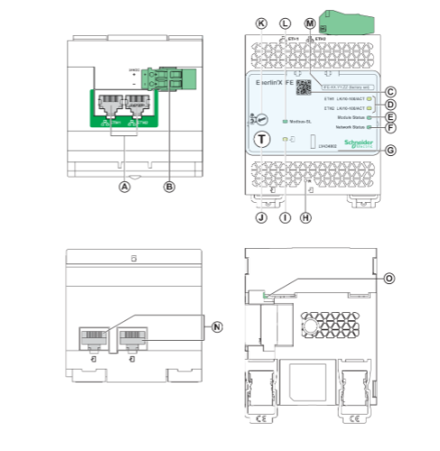
Communication interface configuration
(1) IFM interface (Modbus SL)
Detailed parameters of configuration items
Part number LV434000 (replaces TRV00210/STRV00210)
Communication interface RJ45 port (Modbus SL), stacking interface (optional TRV00217)
Address setting rotary switch definition (1-99), default address 99, address 0 reserved for broadcasting
The power requirement is 24Vdc. It is recommended to use UL certified Level 2 power supply (maximum 3A) and only connect with copper wires
Padlock function enabled: Enable remote control command; Closed: Disabled (except for the 'Set Time' command only)
Automatic configuration method: detect baud rate (4800/9600/19200/38400) and parity; Manual configuration: through EcoStruxure Power Commission software
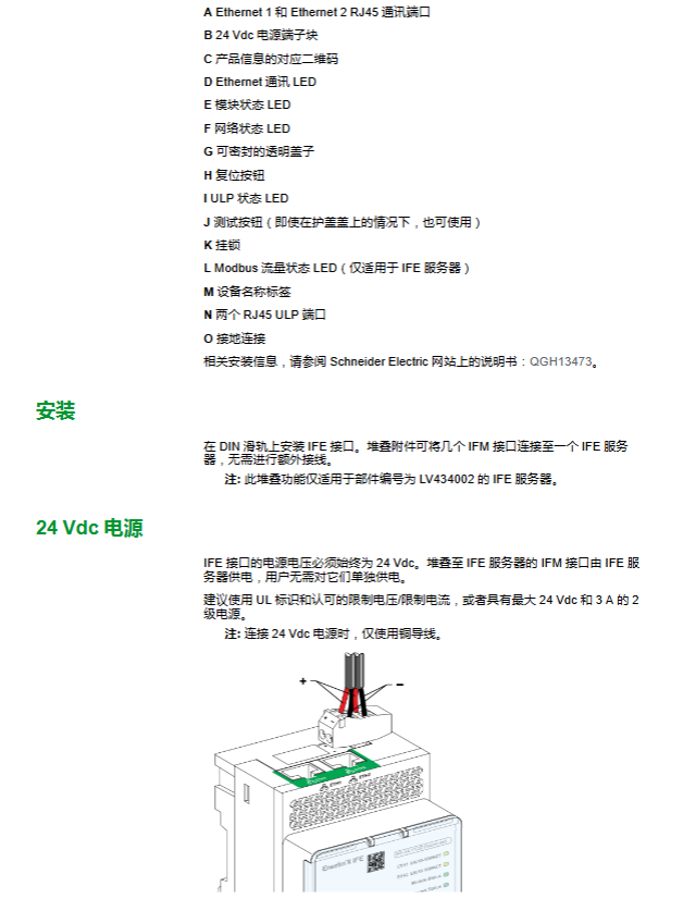
(2) IFE interface (Ethernet)
Detailed parameters of configuration items
Type and Part Number Single Circuit Breaker Interface (LV434001/LV434010), Ethernet Server (LV434002/LV434011)
Communication interface dual RJ45 ports (supporting daisy chain connection), no ring topology protection
IP configuration defaults to DHCP, which can be restored to default by pressing the reset button (1-5 seconds)
The power requirement is 24Vdc, and the stacked IFM interface is powered by the IFE server
The padlock function is the same as the IFM interface, only the "set time" command is not restricted
Featured features include embedded configuration/monitoring of web pages, device discovery services, email alert notifications
Modbus protocol specification
(1) Basic rules of communication
Master slave mode: 1 master device (monitor/PLC), up to 31 slave devices (circuit breakers)
Frame structure: Device address (1 byte) → Function code (1-2 bytes) → Data (n registers) → CRC16 checksum (2 bytes)
Response time: Typical<10ms, maximum value 700ms, recommended request interval ≥ 1 second
Data storage: INT32/64 type adopts Big Endian format (the most significant bit is transmitted first)
(2) Core functional code
Function code name usage restrictions
0x03 Read Hold Register Read Output/Internal Register (such as measurement value, status) Up to 52 registers
0x04 Read Input Register Read Input Register (such as sensor data) Up to 52 registers
0x06 Preset a register to write a single parameter (such as protection threshold)-
0x10 Preset multiple register batch write parameters (such as multiple protection settings) up to 52 registers
0x2B (sub function 0x0F/0x10) Get/set date and time synchronization from device time support broadcast synchronization
0x08 Diagnostic Function Management Counter (such as Bus Error Count)-
(3) Exception code description
Common reasons for the meaning of abnormal codes
0x01 The function code for the illegal function request is not supported
0x02 Illegal data address register address does not exist or is not compatible with firmware version
0x03 Illegal data value written to parameter exceeds allowed range
0x06 Busy device processing other commands
0x07 Negative confirmation programming request cannot be executed
Data collection and registers
(1) Dataset classification
Dataset type, register range, core content advantages
Standard dataset 32000-32341: Circuit breaker status, tripping reasons, current/voltage/power/energy, fast response to harmonic distortion, including high-precision data
The old dataset 12000-12165 is compatible with old devices and includes basic measurement values and status. A single request can read 114 registers
(2) Core module register
① MicroLogic trip unit (key register)
Register type, address range, core data update frequency
Real time measurement of 1000-1146 phase current (IA/IB/IC), line voltage (VAB/VBC/VCA), frequency of 1 second
Electricity measurement 2000-2031 Total active energy (kWh), total reactive energy (kVARh) 5 seconds
Protection parameter 8754-8930: Long delay Ir, short delay Isd, and instantaneous Ii settings are updated as needed
Log register 5732-29549 alarm logs (10 entries), trip logs (17 entries), maintenance logs (10 entries) event triggers
② BSCM module (circuit breaker status control)
Register type, address range, core data function
Status registers 563-564 Real time monitoring of circuit breaker opening and closing status and electric mechanism mode
Counter 571-582 opening and closing times, command execution times, threshold setting (default 5000), maintenance warning
Event log 602-652 10 event records (including timestamp and event type) fault tracing
③ IO module
Register Type Address Range (IO1) Core Data Function
Analog input 13824-13929 Pt100 temperature (-50~250 ℃), data validity, environmental monitoring
Digital input/output 13930-14000 6-channel input status, 3-channel output status switch control
Alarm status 203-205 User defined alarm (201-210) Activation status abnormal warning
Remote Command and Control
(1) Command execution process
Load command parameters into buffer (registers 8000-8015)
Send requests through Modbus function 16 (write multiple registers)
Read command status register 8021 and confirm if it is being executed (0x0003)
Verify if the command code of register 8020 matches the request
Read error code (register 8021 least significant bit), 0 indicates successful execution
(2) Example of Key Commands
Command Name Command Code Permission Requirements Core Parameters
Circuit breaker opening 904 administrator/operator has no additional parameters
Circuit breaker closing 905 administrator/operator has no additional parameters
Reset minimum/maximum value 46728 Administrators/operators need to specify the reset object (current/voltage/power, etc.)
Long delay protection setting 45192 administrator Ir setting value, tr delay (500~16000ms)
Password Modification - Administrator Old Password+New Password (4 ASCII characters)
(3) Permission and Security Control
User profiles: Administrator (highest authority), Service, Engineer, Operator (hierarchical authority)
Password rule: Default password (0000/111/2222/3333), must be changed for the first use
Write protection: dual protection of hardware padlock and software password to prevent illegal modification of protection parameters
Log audit: All operations (command execution, parameter modification) are recorded with timestamp logs
Safety and Maintenance Standards
Operation requirements: Installation and maintenance must be carried out by qualified electrical personnel, and wiring specifications must be strictly followed
Network Security: Disable unused ports/accounts, deploy firewalls, network segmentation
Firmware update: Ensure compatibility through EcoStruxure Power Commission software update
Maintenance indicator: By reading the usage time, contact wear rate, and tripping times of the circuit breaker through the register, a maintenance warning is triggered
- YOKOGAWA
- Reliance
- ADVANCED
- SEW
- ProSoft
- WATLOW
- Kongsberg
- FANUC
- VSD
- DCS
- PLC
- man-machine
- Covid-19
- Energy and Gender
- Energy Access
- Renewable Integration
- Energy Subsidies
- Energy and Water
- Net zero emission
- Energy Security
- Critical Minerals
- A-B
- petroleum
- Mine scale
- Sewage treatment
- cement
- architecture
- Industrial information
- New energy
- Automobile market
- electricity
- Construction site
- HIMA
- ABB
- Rockwell
- Schneider Modicon
- Siemens
- xYCOM
- Yaskawa
- Woodward
- BOSCH Rexroth
- MOOG
- General Electric
- American NI
- Rolls-Royce
- CTI
- Honeywell
- EMERSON
- MAN
- GE
- TRICONEX
- Control Wave
- ALSTOM
- AMAT
- STUDER
- KONGSBERG
- MOTOROLA
- DANAHER MOTION
- Bentley
- Galil
- EATON
- MOLEX
- Triconex
- DEIF
- B&W
- ZYGO
- Aerotech
- DANFOSS
- KOLLMORGEN
- Beijer
- Endress+Hauser
- schneider
- Foxboro
- KB
- REXROTH
- YAMAHA
- Johnson
- Westinghouse
- WAGO
- TOSHIBA
- TEKTRONIX
- BENDER
- BMCM
- SMC
- HITACHI
- HIRSCHMANN
- XP POWER
- Baldor
- Meggitt
- SHINKAWA
- Other Brands
- UniOP
- KUKA
- IBA
- Beckhoff
-
LTI SC52.0040.0012.0000.0 - Servo Drive
-
Lti SC52.0040.0012.0000.0 - Servo Drive
-
Milton Industries LTI Tool By Milton LT1240 - 1/2" Drive Lugnut Remover
-
LTi Drives SO84.200.P030.0000.0-W - Servo Spindle Drive
-
LTI DRIVES LSP08-035-320-30-B0R1PY170 - Servo Motor
-
LTI DRIVES SE84.200.SC00.0001.0-W - Servo Drive
-
Lust CDE34.005.W2.2 - Lti Drives Controller
-
LTi SO84.012.0030.0011.2 - ServoOne Servo Drive
-
LTi Drives SO CM-P.0010.11.00.0 - Servo Drive Controller
-
LTi CDE34.017.W3.0 - Servo Drive
-
LTI Drives CDB32.004, C2.0,SH - Positioning Controller
-
LUST CM-CAN1 - LTi DRIVES Communication Module
-
LTi SO84.012.1030.0000.2 - Servo Drive
-
LTI MOOG CDE54.044 - PITCHMASTER FREQUENCY CONVERTER 181-01019
-
MOOG LTI 181-01019 CDE54.044 - PITCHMASTER FREQUENCY CONVERTER
-
Lust LTi Drives CDE34.010,D2.0 - Servo Drive Controller
-
LTI SO84.032.0003.0101.2 - Servo Drive
-
Seagate 9CC132-302 Harris LTI-CS IRT-34-0021-01 - Hard Drive 160GB
-
LTI SO84.032.0003.0001.2 - Servo Drive
-
LTI SO24.007.0070.0000.1 - SERVO CONTROLLER
-
LTi drive CDA32.003.C3.0.H05-01.PC1 - Servo Drive
-
LTI SO84.016.0030.0000.2 - SERVO CONTROLLER
-
LUST LTI CD A34.008,W1.4, BR - SERVO DRIVE
-
MOOG LTI 181-01019 CDE54.044 - PITCHMASTER FREQUENCY CONVERTER
-
LTI MOOG 181-01019 - PITCH Master Servo Drive CDE54.044
-
LTI SERVO ONE SO84.045.0030.0001.2-W - Drive
-
LUST LTi SO84.032.0040.0000.2 - SERVO ONE DRIVE
-
LTi Drives LSH-074-2-30-3 20/T1,G6.1M - SERVO MOTOR
-
LTI SO84.016.0000.0101.2 - servo drive
-
LTI SA54.0550.0033.0000.0 - Servo Drive
-
LTI SA54.0550.0033.0000.0 - Servo Drive
-
LTI LT 4850 - 3/8" Drive 3-Pc Twist Socket Transmission Drain Plug Removal System
-
LTI Tools LT4400-30 Lock Technology - 3/4" Twist Socket 1/2" Drive Lugnut Remover
-
LTI Tools LT-1400C - 1/2 Drive Wheel Torque Extension Tool
-
LTI Tools LT1250 - 1/2" Drive Dual Sided Socket Lug Nut Remover Tool
-
LTI SO84.032.0003.0101.2 - Servo Drive
-
LTI MOOG 181-01019 - PITCH Master Servo Drive CDE54.044
-
MOOG LTI 181-01019 CDE54.044 - PITCHMASTER FREQUENCY CONVERTER
-
MOOG LTI 181-01019 CDE54.044 - PITCHMASTER FREQUENCY CONVERTER
-
MOOG LTI 181-01019 CDE54.044 - PITCHMASTER FREQUENCY CONVERTER
-
LTI SA54.0550.0033.0000.0 - Servo Drive
-
LTI Tools LT-4800 - 7 Piece Twist Socket 3/8" Drive Oil Drain Plug Removal Set
-
LTI SA54.0550.0033.0000.0 - Servo Drive
-
LTI Drive SO24.007.00300000.0 - Servo Drive
-
LTI TOOLS LTI 1400-I - Drive Wheel Torque Extension
-
LTI Tools LT4400-3 - 3/4" 19mm Twist Socket 1/2" Drive Lugnut
-
LTI TOOLS LTI 1400-BB - Drive Wheel Torque Extension
-
LTI SO84.032.0003.0101.2 - Servo Drive
-
LTI Tools LT-4512 - 3/8" Drive 12mm Twist Socket
-
LTI MOTION Luster SO84.032.0003.0001.2 - Servo Drive
-
LTI Tool By Milton LT1600P - 1" Drive Torx Stick
-
LTI Lust VF1424L,HF,OP2,S56 - Variable Frequency Drive
-
LUST CDA32.004,C1.4,H08,B0 - SERVO DFRIVE CM-CAN1 Module
-
LTI SO84.045.0002.0001.2-W - Drive
-
LTI Lust VF1404M,C9,PT1,BR1 - Inverter Type VF1404M
-
LTI SA54.0550.0033.0000.0 - Servo Drive
-
LTI Tools LT-1400C - 1/2" Drive Wheel Torque Extension
-
Lust LTI DRiVES CDA32.006, C3.0, H09 - Variateur De Fr茅quence Frequency Inverter
-
LTI MOOG CDE54.044 - PITCH master SERVO DRIVE
-
LTI MOOG CDE54.044 - PITCH master SERVO DRIVE
-
LTI SO84.143.0020.0101.2-W - servo drive
-
LTI MOTION SC34.0200.0011.0000.0 - Servo drives
-
LTI SO84.032.0003.0001.2 - Servo Drive
-
LTI DRIVES GmbH MS100 - Assembly Set Mounting Kit
-
LTI SO84.032.0003.0001.2 - Servo Drive
-
LTI SO84.032.0003.0001.2 - Servo Drive
-
LTI MOTION SO84.032.0003.0101.2 - servo drive
-
LTI SO84.032.0003.0101.2 - Servo Drive
-
LTI MOOG CDE54.044 - PITCH master SERVO DRIVE
-
LTI MOTION CDE32.004.C2.4 - Servo drives
-
LTI CDD34.032锛學x.x锛孊R锛孭C1 - Servo Drive
-
Lust LTI DRiVES CDA32.006, C3.0, H09 - Inversor De Frecuencia Frequency Inverter
-
Lust SO84.008.0030.1000.0 - Servo One LTi Drive
-
LTI MOTION SO84.032.0003.0101.2 - Servo drives
-
LUST LTi CDA32.004,C1.4 - SERVO DRIVE
-
LTI MOOG CDE54.044 - PITCH Master SERVO DRIVE
-
LTI KEBA CDB32.004 C2.7, SH - PN: 08673530 Frequency Inverter
-
LTI Tools LT-1400C - 1/2" Drive Wheel Torque Extension
-
LTI LT1400-E - 1/2" Drive Wheel Torque Extension
-
LTI MOOG 181-01019 - PITCH master SERVO DRIVE CDE54.044
-
LTI LSN-097-0510-30-560/T1 - Actuator Motor
-
LTI Tools LT 4800 - 7 Piece 3/8" Drive Twist Socket Oil Drain Plug Removal System
-
LTI DRIVES GmbH MS100 - MONTAGESET Assembly Set Mounting Kit
-
Lti SC52.0040.0012.0000.0 - Servo Drive
-
LTI DRIVES GmbH MS100 - Juego De Montaje Assembly Set Mounting Kit
-
LTi DSM4-14.2-21R83-200 - Drives servomoteur Servo Motor
-
MOOG CDE 54.044.GDA - Pitch Master Industrielle Turbine Lti Drive
-
LTI SO24.004.0030.1000.0 - Servo Drive Controller
-
Lti MOOG CDE54.044 - Pitch Master Servo Drive
-
Lust LTI DRiVES CDA32.006, C3.0, H09 - Inverter
-
LTI MOTION GMBH CDB34.006,W3.0,PC1,H39 - Frequency inverter
-
LTI SO84.032.0003.0001.2 - Servo Drive
-
MOOG CDE 54.044.D - Pitch Master Industrielle Turbine Lti Drive
-
LTI TOOLS LT-1460 - 1/2" DRIVE WHEEL TORQUE EXTENSION KIT 5 PIECE SET
-
Lust Cdb32.003, C2.4 - Lti Drives Servoregulador Frecuencia Servo Controller Inverter
-
Lust LTI DRIVES CDA32.006, C3.0, H09 - Frequency Inverter
-
Lust Lti SO82.004.0030.0000.2 - Servo Drive
-
LTI MOTION SC34.0200.0011.0000.0-SL - Servo drives
-
LTI MOTION SA54.0075.0033.0000.0 - Servo drives
-
LTI MOTION SC32.0075.1011.0000.0 - Servo drives
-
LTI Servo-One Junior SO22.006.0080.1000.0 - Servo Controller Servoregler
-
LUST CDA32.004, C1.4, H08, B0 - Servo Drive & LTI CM-CAN1 Module
-
LTI DRIVES LSP08-035-320-30-B0R1PY170 - Servo Motor
-
LUST LTI CDA32.004,C1.4.H08.B0 - SERVO CONTROLLER DRIVES
-
LUST LTi DRiVES CDS44.072LC1.2 - Servo Drive
-
Lti Servo-One Junior SO22.006.0082.1000.0 - Servo Controller Servoregler
-
LUST CDA32.008,C2.0,HF - Lti DRIVES Spindle Drive Inverter
-
LTI SO22.003.0082.0000.0 - Servo Drives One junior Servo Controller Servoregler
-
Lust Lti Drives CM-CAN1 - Communication Module
-
LUST Lti Drives Vf1202s, G8, I6 - Frequency Inverter Drive
-
LTI DRIVES BR-090.03.540.UR.H38 - Bremswiderstand Brake Resistor
-
LTi DRIVES PM-E40.2DRA054P - Wind Turbine Pitch Control Inverter
-
LTi Drives GmbH br-110.01.540-UR - Brake Resistor
-
LTI Drives LSN-097-0960-30-0560/T1,S4,B - Servo Motor
-
LUST CDA34.006.C2.0 - LTI Drives Servoregler
-
LUST LTI DRIVES SERVO ONE JUNIOR SO24.002.0020.0000.1 - Servo Drive Controller
-
LTI MOTION SO84.032.0003.0001.2 - Servo drives
-
LTI DDTD750V2-120 - IBOP ACTUATOR CYLINDER FOR TOP DRIVE
-
LTI CDE32.004, C2.4 - SERVO DRIVE
-
LUST LTI DRIVES CDD34.017 W3.4PC1 - Servo Drive Controller
-
LTI CDA3208,C3,0,HF - AC SERVO DRIVE
-
LUST LTI DRIVES LSH-074-3-30-560/T1,G6.1S - SERVO MOTOR
-
LUST Lti CDB32.004.C2.4.SH - AC Servo Drive
-
LTi CDA32.006, C3.0, H09 - Servo Drive
-
LTI SO22.003.0010.0000.0 - Servo Drive Servo one junior Servoregler Controller
-
LTi Drives DSM4-14.2-21R83-200 - Servo Motor
-
LUST Lti Drives Lsh-097-1-30-560/T1, 1R - Servomotor
-
LTI 1237 - 7 Piece 1/2" Drive Flip Socket Set

K-JIANG

Add: Jimei North Road, Jimei District, Xiamen, Fujian, China
Tell:+86-15305925923