
K-WANG


User Guide for SCHNEIDER Service Interface (Part Number LV485500)
User Guide for SCHNEIDER Service Interface (Part Number LV485500)
The user guide for Schneider Service Interface (part number LV485500) is primarily used for on-site testing and configuration of MasterPact NT/NW, ComPacT, PowerPacT, and EasyPact series circuit breakers. It supports automatic trip curve testing, zone selection interlock (ZSI) testing, forced trip testing, primary injection testing preparation, and Enerlin'X equipment configuration for communication/non communication MicroLogic trip units through EcoStruxure Power Commission (EPC) software. It requires the use of dedicated cables (such as LV485512SP/LV485513SP) for power supply (24Vdc). The operation must be performed by qualified personnel and comply with safety regulations such as password management and power-off protection. After testing, a project report can be generated to verify the effectiveness of equipment protection functions. Sex.
Document Overview
(1) Core positioning and scope of application
Category key information
Document Usage: Installation, Connection, Testing, Configuration, and Troubleshooting Guide for Service Interface
Applicable tool Service Interface (part number LV485500, firmware ≥ 001.001.040)+EPC software
Applicable equipment circuit breakers: MasterPact NT/NW, EasyPact MVS, ComPacT NS/NSX, PowerPacT P/R/H/J/L series
Release unit: MicroLogic 2.0~7.0 series (communication/non communication), ET release system
Enerlin'X devices: IO modules, FDM121 displays, IFE/IFM interfaces, etc
Core Value: On site verification of circuit breaker protection function, configuration of equipment parameters, firmware updates, and generation of test reports for acceptance
(2) Safety and compliance requirements
Personnel qualifications: Only qualified electrical personnel are required to perform installation, testing, and maintenance, and must have the ability to operate equipment and identify risks
Network Security: First use must change default password, disable unused ports/services/default accounts, deploy firewalls and network segmentation
Electrical safety: During testing, the circuit breaker may trip, causing downstream power outages, and preventive measures need to be planned in advance; To avoid the risk of arc flash and electric shock, execute the operation after confirming that there is no danger involved
Compliance standards: Complies with IEC 61010-1, IEC 60947-6-2, UL 61010-1 and other standards, with certification covering cULus, CE, etc
Service Interface Hardware and Technical Parameters
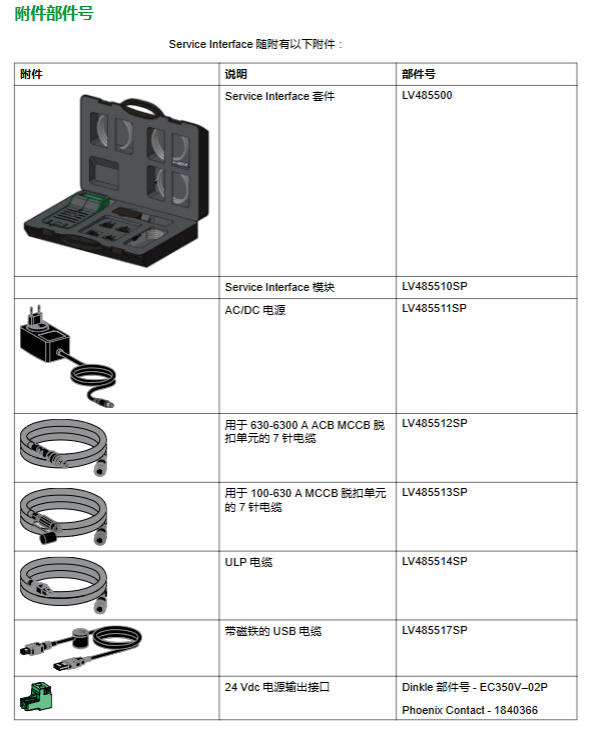
(1) Hardware composition and accessories
Specific specifications of component types
Core interface 24Vdc power input port, 24Vdc power output port (120mA), Mini-B USB port, test port, magnetic mount (magnetic installation)
Indicator light power LED (green: powered on), USB LED (green: connected), status LED (orange: boot mode), test port LED (green/blue/orange: corresponding to different device connections)
Special accessory 7-pin cable (LV485512SP: 630-6300A trip unit; LV485513SP: 100-630A trip unit, ULP cable (LV485514SP: Enerlin'X equipment), AC/DC power adapter (110-230Vac to 24Vdc), USB cable with magnet (LV485517SP)
(2) Key technical parameters
Specific numerical values for parameter categories
Electrical parameter input voltage: 24Vdc (-20%~+10%), maximum 525mA
Output voltage: 24Vdc (-20%~+10%), maximum 120mA
Rated power: Service Interface 10W, Adapter 12W
Environmental parameters Operating temperature: -10 ℃~+55 ℃ (14 ° F~+131 ° F)
Storage temperature: -40 ℃~+85 ℃ (-40 ° F~+185 ° F)
Protection level: ULV0 (compliant with IEC/EN 60068-2-30)
Pollution level: Level 3
Mechanical parameters Mechanical impact: Complies with IEC 62262 IK07
Installation methods: wall mounted, countertop, magnetic suction
Core testing functions (classified by circuit breaker type)
(1) MasterPact NT/NW, EasyPact MVS, ComPacT NS, PowerPacT P/R circuit breakers
Compatibility of release unit
The type of trip unit supports testing function
Communication type (such as MicroLogic 2.0A/E, 5.0P/H, 6.0 series) automatic trip curve testing, ZSI testing, forced trip testing, primary injection testing preparation, configuration
Non communication type (such as MicroLogic 2.0/3.0, ET 2. I) automatic trip curve test, forced trip test (without configuration/firmware update function)
Core testing process (taking communication unit as an example)
Connection: Connect the Service Interface to the test port of the trip unit using LV485512SP cable, and connect the 24Vdc power supply
Device discovery: EPC software → Start device discovery → USB/SRIAL → Select device → Enter project information → Connect device
Test execution:
Automatic trip curve test: Select pre configured/custom test points → Enter administrator password → Reset closing circuit breaker → Execute test (can be aborted) → Repeat test → View results
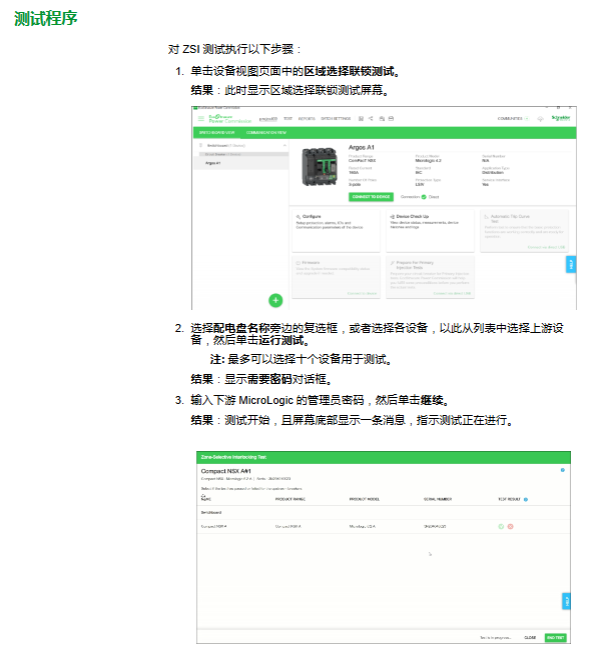
ZSI test: Select upstream devices (≤ 10 units) → Enter password → Run test → Confirm LED flashing status → End test
Forced tripping test: Equipment inspection → Confirm closing → Enter password → Confirm tripping → Generate results
Primary injection preparation: Select test type → Enter password → Suppress thermal memory/ground fault → Manually inject current → Test completed → Restore normal mode
Report generation: EPC software → Report → Project Report → Save/Print
(2) ComPacT NSX, PowerPacT H/J/L circuit breakers
Compatibility of release unit
MicroLogic release unit supports functions
1.2/1.3/2.2/3.2/4.3 series automatic trip curve test, forced trip test, primary injection preparation
5.2/5.3 B/A/E, 6.2/6.3 A/E, 7.2/7.3 E series automatic trip curve testing, ZSI testing, forced trip testing, primary injection preparation, alarm simulation, configuration, firmware update
Featured feature: Alarm simulation
Simulated objects: warning (PAL Ir/IG/I Δ n), 10 user-defined alarms
Verification scenario: FDM121 display (LED flashing/constant, pop-up, alarm history), communication network (Modbus register), SDx module (output status change)
Process: EPC Configuration → Alarm Tab → Select Activate Alarm → Enter Password → Simulate → Verify Results
Enerlin'X device configuration
(1) Compatible devices and functions
Equipment Name Part Number Example Support Function
IO input/output module LV434063 configuration, firmware update
FDM121 Front Display Module TRV00121/STRV00121 Firmware Update
IFE Ethernet interface LV434001 firmware update
IFM Modbus SL interface LV434000 configuration, firmware update
BSCM Circuit Breaker Status Control Module LV434205- (only compatible with connections)
(2) Connection and operation
Connection method: Use ULP cable (LV485514SP) to connect the Service Interface to the RJ45 ULP port of the device
Core operation: EPC software → Configure device parameters (some models), update firmware → Synchronize to other Enerlin'X devices in IMU
Firmware updates and troubleshooting
(1) Firmware update process
EPC software → Connect devices directly → Analyze firmware status → Check Service Interface → Next step
Enter password → click 'Upgrade' → wait for completion (cannot be disconnected)
View current/latest firmware version → Close window
Attention: The firmware adopts Schneider digital signature, and the validity of the certificate needs to be checked regularly
(2) Common troubleshooting
Possible causes and solutions for the fault phenomenon
Unrecognized release unit test interval<5 seconds, disconnect → wait for 5 seconds → reconnect
The primary injection test tripped too early, and the suppression function was not disabled before stopping and restarting the suppression function after tripping
Ground fault test without tripping injection current insufficient/MDGF/SGR configuration increases current → Check compatibility → Switch to primary injection test
Automatic tripping test failed (tripping<10ms), closing lock/instantaneous override protection ensures circuit breaker closing → verify protection level
- YOKOGAWA
- Reliance
- ADVANCED
- SEW
- ProSoft
- WATLOW
- Kongsberg
- FANUC
- VSD
- DCS
- PLC
- man-machine
- Covid-19
- Energy and Gender
- Energy Access
- Renewable Integration
- Energy Subsidies
- Energy and Water
- Net zero emission
- Energy Security
- Critical Minerals
- A-B
- petroleum
- Mine scale
- Sewage treatment
- cement
- architecture
- Industrial information
- New energy
- Automobile market
- electricity
- Construction site
- HIMA
- ABB
- Rockwell
- Schneider Modicon
- Siemens
- xYCOM
- Yaskawa
- Woodward
- BOSCH Rexroth
- MOOG
- General Electric
- American NI
- Rolls-Royce
- CTI
- Honeywell
- EMERSON
- MAN
- GE
- TRICONEX
- Control Wave
- ALSTOM
- AMAT
- STUDER
- KONGSBERG
- MOTOROLA
- DANAHER MOTION
- Bentley
- Galil
- EATON
- MOLEX
- Triconex
- DEIF
- B&W
- ZYGO
- Aerotech
- DANFOSS
- KOLLMORGEN
- Beijer
- Endress+Hauser
- schneider
- Foxboro
- KB
- REXROTH
- YAMAHA
- Johnson
- Westinghouse
- WAGO
- TOSHIBA
- TEKTRONIX
- BENDER
- BMCM
- SMC
- HITACHI
- HIRSCHMANN
- XP POWER
- Baldor
- Meggitt
- SHINKAWA
- Other Brands
- UniOP
- KUKA
- IBA
- Beckhoff
-
LTI SC52.0040.0012.0000.0 - Servo Drive
-
Lti SC52.0040.0012.0000.0 - Servo Drive
-
Milton Industries LTI Tool By Milton LT1240 - 1/2" Drive Lugnut Remover
-
LTi Drives SO84.200.P030.0000.0-W - Servo Spindle Drive
-
LTI DRIVES LSP08-035-320-30-B0R1PY170 - Servo Motor
-
LTI DRIVES SE84.200.SC00.0001.0-W - Servo Drive
-
Lust CDE34.005.W2.2 - Lti Drives Controller
-
LTi SO84.012.0030.0011.2 - ServoOne Servo Drive
-
LTi Drives SO CM-P.0010.11.00.0 - Servo Drive Controller
-
LTi CDE34.017.W3.0 - Servo Drive
-
LTI Drives CDB32.004, C2.0,SH - Positioning Controller
-
LUST CM-CAN1 - LTi DRIVES Communication Module
-
LTi SO84.012.1030.0000.2 - Servo Drive
-
LTI MOOG CDE54.044 - PITCHMASTER FREQUENCY CONVERTER 181-01019
-
MOOG LTI 181-01019 CDE54.044 - PITCHMASTER FREQUENCY CONVERTER
-
Lust LTi Drives CDE34.010,D2.0 - Servo Drive Controller
-
LTI SO84.032.0003.0101.2 - Servo Drive
-
Seagate 9CC132-302 Harris LTI-CS IRT-34-0021-01 - Hard Drive 160GB
-
LTI SO84.032.0003.0001.2 - Servo Drive
-
LTI SO24.007.0070.0000.1 - SERVO CONTROLLER
-
LTi drive CDA32.003.C3.0.H05-01.PC1 - Servo Drive
-
LTI SO84.016.0030.0000.2 - SERVO CONTROLLER
-
LUST LTI CD A34.008,W1.4, BR - SERVO DRIVE
-
MOOG LTI 181-01019 CDE54.044 - PITCHMASTER FREQUENCY CONVERTER
-
LTI MOOG 181-01019 - PITCH Master Servo Drive CDE54.044
-
LTI SERVO ONE SO84.045.0030.0001.2-W - Drive
-
LUST LTi SO84.032.0040.0000.2 - SERVO ONE DRIVE
-
LTi Drives LSH-074-2-30-3 20/T1,G6.1M - SERVO MOTOR
-
LTI SO84.016.0000.0101.2 - servo drive
-
LTI SA54.0550.0033.0000.0 - Servo Drive
-
LTI SA54.0550.0033.0000.0 - Servo Drive
-
LTI LT 4850 - 3/8" Drive 3-Pc Twist Socket Transmission Drain Plug Removal System
-
LTI Tools LT4400-30 Lock Technology - 3/4" Twist Socket 1/2" Drive Lugnut Remover
-
LTI Tools LT-1400C - 1/2 Drive Wheel Torque Extension Tool
-
LTI Tools LT1250 - 1/2" Drive Dual Sided Socket Lug Nut Remover Tool
-
LTI SO84.032.0003.0101.2 - Servo Drive
-
LTI MOOG 181-01019 - PITCH Master Servo Drive CDE54.044
-
MOOG LTI 181-01019 CDE54.044 - PITCHMASTER FREQUENCY CONVERTER
-
MOOG LTI 181-01019 CDE54.044 - PITCHMASTER FREQUENCY CONVERTER
-
MOOG LTI 181-01019 CDE54.044 - PITCHMASTER FREQUENCY CONVERTER
-
LTI SA54.0550.0033.0000.0 - Servo Drive
-
LTI Tools LT-4800 - 7 Piece Twist Socket 3/8" Drive Oil Drain Plug Removal Set
-
LTI SA54.0550.0033.0000.0 - Servo Drive
-
LTI Drive SO24.007.00300000.0 - Servo Drive
-
LTI TOOLS LTI 1400-I - Drive Wheel Torque Extension
-
LTI Tools LT4400-3 - 3/4" 19mm Twist Socket 1/2" Drive Lugnut
-
LTI TOOLS LTI 1400-BB - Drive Wheel Torque Extension
-
LTI SO84.032.0003.0101.2 - Servo Drive
-
LTI Tools LT-4512 - 3/8" Drive 12mm Twist Socket
-
LTI MOTION Luster SO84.032.0003.0001.2 - Servo Drive
-
LTI Tool By Milton LT1600P - 1" Drive Torx Stick
-
LTI Lust VF1424L,HF,OP2,S56 - Variable Frequency Drive
-
LUST CDA32.004,C1.4,H08,B0 - SERVO DFRIVE CM-CAN1 Module
-
LTI SO84.045.0002.0001.2-W - Drive
-
LTI Lust VF1404M,C9,PT1,BR1 - Inverter Type VF1404M
-
LTI SA54.0550.0033.0000.0 - Servo Drive
-
LTI Tools LT-1400C - 1/2" Drive Wheel Torque Extension
-
Lust LTI DRiVES CDA32.006, C3.0, H09 - Variateur De Fr茅quence Frequency Inverter
-
LTI MOOG CDE54.044 - PITCH master SERVO DRIVE
-
LTI MOOG CDE54.044 - PITCH master SERVO DRIVE
-
LTI SO84.143.0020.0101.2-W - servo drive
-
LTI MOTION SC34.0200.0011.0000.0 - Servo drives
-
LTI SO84.032.0003.0001.2 - Servo Drive
-
LTI DRIVES GmbH MS100 - Assembly Set Mounting Kit
-
LTI SO84.032.0003.0001.2 - Servo Drive
-
LTI SO84.032.0003.0001.2 - Servo Drive
-
LTI MOTION SO84.032.0003.0101.2 - servo drive
-
LTI SO84.032.0003.0101.2 - Servo Drive
-
LTI MOOG CDE54.044 - PITCH master SERVO DRIVE
-
LTI MOTION CDE32.004.C2.4 - Servo drives
-
LTI CDD34.032锛學x.x锛孊R锛孭C1 - Servo Drive
-
Lust LTI DRiVES CDA32.006, C3.0, H09 - Inversor De Frecuencia Frequency Inverter
-
Lust SO84.008.0030.1000.0 - Servo One LTi Drive
-
LTI MOTION SO84.032.0003.0101.2 - Servo drives
-
LUST LTi CDA32.004,C1.4 - SERVO DRIVE
-
LTI MOOG CDE54.044 - PITCH Master SERVO DRIVE
-
LTI KEBA CDB32.004 C2.7, SH - PN: 08673530 Frequency Inverter
-
LTI Tools LT-1400C - 1/2" Drive Wheel Torque Extension
-
LTI LT1400-E - 1/2" Drive Wheel Torque Extension
-
LTI MOOG 181-01019 - PITCH master SERVO DRIVE CDE54.044
-
LTI LSN-097-0510-30-560/T1 - Actuator Motor
-
LTI Tools LT 4800 - 7 Piece 3/8" Drive Twist Socket Oil Drain Plug Removal System
-
LTI DRIVES GmbH MS100 - MONTAGESET Assembly Set Mounting Kit
-
Lti SC52.0040.0012.0000.0 - Servo Drive
-
LTI DRIVES GmbH MS100 - Juego De Montaje Assembly Set Mounting Kit
-
LTi DSM4-14.2-21R83-200 - Drives servomoteur Servo Motor
-
MOOG CDE 54.044.GDA - Pitch Master Industrielle Turbine Lti Drive
-
LTI SO24.004.0030.1000.0 - Servo Drive Controller
-
Lti MOOG CDE54.044 - Pitch Master Servo Drive
-
Lust LTI DRiVES CDA32.006, C3.0, H09 - Inverter
-
LTI MOTION GMBH CDB34.006,W3.0,PC1,H39 - Frequency inverter
-
LTI SO84.032.0003.0001.2 - Servo Drive
-
MOOG CDE 54.044.D - Pitch Master Industrielle Turbine Lti Drive
-
LTI TOOLS LT-1460 - 1/2" DRIVE WHEEL TORQUE EXTENSION KIT 5 PIECE SET
-
Lust Cdb32.003, C2.4 - Lti Drives Servoregulador Frecuencia Servo Controller Inverter
-
Lust LTI DRIVES CDA32.006, C3.0, H09 - Frequency Inverter
-
Lust Lti SO82.004.0030.0000.2 - Servo Drive
-
LTI MOTION SC34.0200.0011.0000.0-SL - Servo drives
-
LTI MOTION SA54.0075.0033.0000.0 - Servo drives
-
LTI MOTION SC32.0075.1011.0000.0 - Servo drives
-
LTI Servo-One Junior SO22.006.0080.1000.0 - Servo Controller Servoregler
-
LUST CDA32.004, C1.4, H08, B0 - Servo Drive & LTI CM-CAN1 Module
-
LTI DRIVES LSP08-035-320-30-B0R1PY170 - Servo Motor
-
LUST LTI CDA32.004,C1.4.H08.B0 - SERVO CONTROLLER DRIVES
-
LUST LTi DRiVES CDS44.072LC1.2 - Servo Drive
-
Lti Servo-One Junior SO22.006.0082.1000.0 - Servo Controller Servoregler
-
LUST CDA32.008,C2.0,HF - Lti DRIVES Spindle Drive Inverter
-
LTI SO22.003.0082.0000.0 - Servo Drives One junior Servo Controller Servoregler
-
Lust Lti Drives CM-CAN1 - Communication Module
-
LUST Lti Drives Vf1202s, G8, I6 - Frequency Inverter Drive
-
LTI DRIVES BR-090.03.540.UR.H38 - Bremswiderstand Brake Resistor
-
LTi DRIVES PM-E40.2DRA054P - Wind Turbine Pitch Control Inverter
-
LTi Drives GmbH br-110.01.540-UR - Brake Resistor
-
LTI Drives LSN-097-0960-30-0560/T1,S4,B - Servo Motor
-
LUST CDA34.006.C2.0 - LTI Drives Servoregler
-
LUST LTI DRIVES SERVO ONE JUNIOR SO24.002.0020.0000.1 - Servo Drive Controller
-
LTI MOTION SO84.032.0003.0001.2 - Servo drives
-
LTI DDTD750V2-120 - IBOP ACTUATOR CYLINDER FOR TOP DRIVE
-
LTI CDE32.004, C2.4 - SERVO DRIVE
-
LUST LTI DRIVES CDD34.017 W3.4PC1 - Servo Drive Controller
-
LTI CDA3208,C3,0,HF - AC SERVO DRIVE
-
LUST LTI DRIVES LSH-074-3-30-560/T1,G6.1S - SERVO MOTOR
-
LUST Lti CDB32.004.C2.4.SH - AC Servo Drive
-
LTi CDA32.006, C3.0, H09 - Servo Drive
-
LTI SO22.003.0010.0000.0 - Servo Drive Servo one junior Servoregler Controller
-
LTi Drives DSM4-14.2-21R83-200 - Servo Motor
-
LUST Lti Drives Lsh-097-1-30-560/T1, 1R - Servomotor
-
LTI 1237 - 7 Piece 1/2" Drive Flip Socket Set

K-JIANG

Add: Jimei North Road, Jimei District, Xiamen, Fujian, China
Tell:+86-15305925923