
K-WANG


ProSoft MVI56-PDPMV1 Module: PROFIBUS DPV1 Master Integration Complete Guide
ProSoft MVI56-PDPMV1 module: Profound analysis of PROFIBUS DPV1 master station integration on ControlLogix platform
In today's highly integrated industrial automation field, seamless and reliable communication between devices is the core of efficient system operation. Rockwell Automation's ControlLogix platform is renowned for its powerful processing capabilities and flexible architecture, while PROFIBUS DP, as one of the world's leading industrial fieldbus standards, is widely used in distributed I/O, drive systems, and intelligent instruments. The MVI56-PDPMV1 module, as a dedicated communication solution launched by ProSoft Technology, serves as a bridge connecting the ControlLogix processor with the PROFIBUS DPV1 network. This guide will be based on the official manual, comprehensively analyzing the technical characteristics, installation configuration, advanced functional applications, and fault diagnosis of the module, providing engineers with a detailed and professional integrated reference.
System Overview and Hardware Preparation
The MVI56-PDPMV1 module is a single slot communication module designed specifically for ControlLogix backplanes. It plays the role of a PROFIBUS DPV1 master station, capable of managing communication with up to 125 PROFIBUS slave devices, supporting advanced functions such as periodic data exchange, non periodic access (DPV1 service), and alarm processing. The introduction of this module enables the ControlLogix processor to easily integrate a wide range of PROFIBUS devices, greatly expanding the system's device access capabilities.
Hardware specifications and requirements
The module itself has clear hardware requirements for the ControlLogix rack. Firstly, the module needs to be installed in a vacant slot of the rack and is required to provide sufficient backplane current. Specifically, the module requires backplane power support of 800 mA @ 5 VDC and 3 mA @ 24 VDC. Engineers must fully consider this requirement when selecting power sources and planning rack layouts to ensure stable power supply for the system. Secondly, the module supports installation in the local rack (same rack as the processor) or remote rack. For remote rack applications, modules communicate with processors through EtherNet/IP or ControlNet networks, which requires the system to have the corresponding network infrastructure and configuration.
Environmental and safety regulations
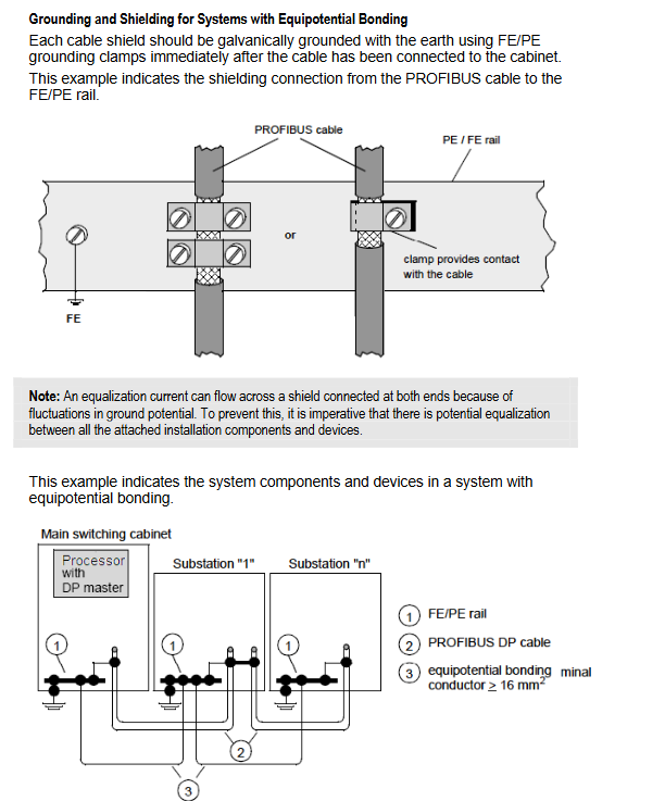
Safety is always the primary consideration in the installation of industrial equipment. The manual clearly states that the module is suitable for hazardous or non hazardous environments of Class I, Division 2, Groups A, B, C, and D. When installing, wiring, and replacing modules, relevant explosion-proof safety regulations must be strictly followed. For example, in hazardous areas, power must be cut off before operation. In addition, the module is equipped with dedicated serial port cables (RS-232 NULL modem cable and RJ45-DB9 adapter) for configuration and debugging at the factory, which are essential tools for initial configuration and later diagnosis.
Software Configuration and Project Establishment
After the hardware installation is completed, software configuration is a key step in putting the module into operation. This process mainly relies on ProSoft Configuration Builder (PCB) software, which is the core tool for managing the MVI56-PDPMV1 module.
1. Installation and project initialization
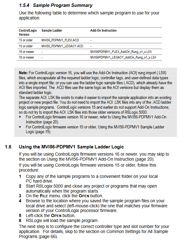
Engineers need to download and install the latest version of PCB software from the ProSoft Technology official website. When using it for the first time, it is necessary to create a project in the software and add the MVI56-PDPMV1 module object. The most basic configuration in module parameter settings is to determine the input and output data word size required for the PROFIBUS network. This value should be set based on the actual total amount of I/O data generated by the connected slave devices. For modules with firmware versions 1.21 and above, a crucial choice is the "working mode": Legacy Mode or Flex Mode. The Legacy Mode mode has a fixed input block size of 250 words and an output block size of 248 words, compatible with early firmware and easy to configure; The Flex Mode mode allows users to flexibly adjust the size of the backplane I/O block based on the actual amount of data (input 12-250 words, output 5-248 words), which is particularly suitable for remote rack applications and can effectively optimize network bandwidth and backplane performance. This selection must strictly match the sample program or add instruction (AOI) type imported later in RSLogix 5000.
2. PROFIBUS network configuration
The configuration of PROFIBUS master and slave is the core function of PCB. Engineers first need to install the GSD file of the slave station equipment, which is provided by the equipment manufacturer and defines the communication characteristics of the slave station. In the "Bus Configuration" window of the PCB, engineers can graphically add master and various slave nodes. For each slave station, it is necessary to configure its PROFIBUS address (usually starting from 3), select its data exchange module (determining the I/O data type and length), and assign it a starting address in the module's internal database. One powerful feature of PCB is the ability to automatically calculate and display "processor network memory mapping", clearly listing the label address range corresponding to all slave I/O data in the ControlLogix processor, providing a direct basis for subsequent PLC logic writing.
For complex networks, the "automatic scanning" function of PCB can greatly improve configuration efficiency. This function can scan all online slave stations on the PROFIBUS network, automatically identify their device identification and configuration information, and attempt to match the installed GSD file to generate a network configuration draft for engineers to review and modify.
Logical integration with ControlLogix processors
After completing the hardware configuration, the module must be logically bound to the ControlLogix processor to achieve data exchange. This is mainly achieved by configuring modules and importing sample code or adding instructions (AOI) in the RSLogix 5000 software.
1. Module configuration
In the I/O configuration tree of RSLogix 5000, a "Generic 1756 Module" needs to be added to represent MVI56-PDPMV1. The key parameters of the configuration must be consistent with the settings in the PCB, especially the communication format (Data-INT), input/output size, and RPI time. RPI time defines the refresh cycle of backplane data between processors and modules. For local racks or EtherNet/IP remote racks, it is recommended to set the RPI to a maximum value of 750ms in Flex mode, as the AOI logic in this mode will use IOT (immediate output) instructions for fast data updates, and a too short RPI will actually increase the burden on the processor.
2. Import example logic and AOI
To simplify integration, ProSoft provides comprehensive sample programs and AOIs. For ControlLogix processors with firmware 16 and above, AOI is strongly recommended. The AOI file (. L5X format) encapsulates data types, controller labels, functional block logic, and call ladder diagrams. After importing, simply configure the module connection path to use it. AOI greatly reduces programming workload and ensures the correctness of communication logic with modules.
Whether using Legacy or Flex mode, AOI provides standardized data interfaces:
PROFIBUSData array: carries periodic input and output data.
Command structure: used to trigger non periodic mailbox commands.
Mailbox structure: Stores parameters and response data for mailbox commands.
Status structure: Contains information such as module status, network status, and slave diagnostics.
Config structure: Stores module configuration information.
Engineers only need to operate these tags in the application to achieve comprehensive monitoring and control of the PROFIBUS network.
Advanced features: Email messaging and non periodic communication
As the main station of DPV1, MVI56-PDPMV1's powerful non periodic communication capability is achieved through the "email message" mechanism. This enables the processor to not only exchange periodic I/O data with the slave station, but also perform advanced operations such as device parameter settings, reading diagnostic information, and handling alarms.
Email message process
The execution of email messages follows a request response mechanism:
Processor sends request: Set command parameters (such as slave address, read-write length, etc.) in the control logic, and then set the corresponding command trigger bit (e.g. MVI56PDPMV1.Command.GetSlaveDiagnostics).
Module processing and response: After receiving the request, the module executes the corresponding DPV1 service with the target slave through the PROFIBUS network and stores the response result in the designated email input tag.
Processor processing response: After the logic detects the completion of the response (such as the corresponding counter increment or status bit change), it reads the result from the email input label.
Example of Key Email Command
Get Slave Diagnostics: Obtaining detailed diagnostic information of a specified slave station is crucial for quickly locating network fault points.
Class 1 Acyclic Read/Write: This is the core service of DPV1, allowing non periodic data read and write to slave stations that support DPV1, commonly used for reading drive parameters, writing configuration data, etc.
Set Slave Address: Modify the PROFIBUS address of the slave station that supports this feature online for network debugging purposes.
Get Live List: Get a list of all active nodes on the current network and their types (master/slave), which is a powerful tool for network diagnosis.
Alarm Handling: The module can automatically receive and cache alarm information sent by DPV1 slave stations, and the processor can query and confirm these alarms through email messages.
By making reasonable use of these email commands, powerful device management, predictive maintenance, and human-computer interaction functions can be developed.
Diagnosis, maintenance, and troubleshooting
A reliable system cannot do without effective diagnostic methods. The MVI56-PDPMV1 module provides multi-level diagnostic tools.
1. Front panel LED indicator light
The front panel of the module integrates a series of status LEDs, which can quickly indicate the health status of the system:
OK: The green light indicates that the module is functioning properly; The red light indicates a program error or configuration mismatch, which may be caused by incompatible example logic.
BP ACT: Amber light on indicates successful backplane communication; Extinguishing indicates a failed connection to the processor.
APP STATION: Amber light on usually indicates that the checksum of the input/output block does not match, and it is necessary to check the PCB configuration and the checksum in RSLogix.
PROFIBUS Master LEDs: located behind the module door, providing more detailed PROFIBUS network status. COM STAT green light indicates normal communication with all configured slave stations; DBASE STAT green light indicates that the configuration database has been downloaded; The green light of MSTR STAT indicates that the main station is in operation mode.
2. Serial port debugging menu
By connecting the CFG port of the PC and module through the accompanying serial cable, a powerful text-based debugging menu can be accessed in the "Diagnosis" window of the PCB. By using command keys (such as [?] to display the main menu, [2] to view PROFIBUS data), engineers can directly view the internal database, operation status, slave configuration list (SLAVE CFG LIST), and actual communication slave list (TRANSFER LIST) bitmap comparison of the module. These raw data are the most direct basis for diagnosing issues such as PROFIBUS network disconnections, slave disconnections, and address conflicts.
3. Online monitoring and MSG commands
In the online state of RSLogix 5000, monitoring the Status tag structure provided by AOI can obtain real-time module status, communication status of each slave station, and diagnostic flags. In addition, sending the UWP iveList or Gets laveDiagnostics email command and observing the returned results in the tag window is a practical method for online network scanning and in-depth diagnosis.
4. Common problem troubleshooting
Module unable to communicate with processor: Check if the module is installed in the correct slot, if the module configuration slot numbers in RSLogix match, if the RPI settings are reasonable, and if the processor is running. Check the status of BP ACT LED.
PROFIBUS communication failure: Check if the PROFIBUS cable wiring, terminal resistance settings, and baud rate are consistent with the slave station. Use the serial port menu or view the slave status list online. Ensure that the slave address matches the PCB configuration.
Email command unresponsive: Check if the command triggering logic is executed correctly and if the slave station supports the DPV1 service. Check the error code in the email response.
Configuration mismatch error: After modifying the PROFIBUS configuration in the PCB, it is necessary to re download the configuration to the module and follow the manual instructions to delete the old AOI and related labels and data types in RSLogix, and then re import the new one exported from the PCB L5X file.
Summary and Best Practices
The MVI56-PDPMV1 module is a specialized tool for achieving efficient interconnection between the ControlLogix system and PROFIBUS DPV1 worldwide. Its successful integration relies on a systematic understanding of hardware specifications, software configuration processes, communication modes, and diagnostic methods. To ensure the smooth implementation and long-term stable operation of the project, it is recommended to follow the following best practices:
Planning first: Conduct a detailed evaluation of the number of network nodes, data volume, and functional requirements before procurement, and determine the number of modules and working modes.
Version matching: Ensure compatibility between PCB software, module firmware, ControlLogix firmware, and the sample program versions used.
Configuration synchronization: Strictly ensure that the parameters (data size, checksum) in the PCB are completely consistent with the module configuration in RSLogix 5000.
Make good use of tools: make full use of PCB's memory mapping report, AOI's standardized interface, and serial port debugging menu to simplify development and diagnosis.
Standardized documentation: Timely backup PCB project files, GSD files, and final generated processor import files, and establish complete engineering documentation.
- YOKOGAWA
- Reliance
- ADVANCED
- SEW
- ProSoft
- WATLOW
- Kongsberg
- FANUC
- VSD
- DCS
- PLC
- man-machine
- Covid-19
- Energy and Gender
- Energy Access
- Renewable Integration
- Energy Subsidies
- Energy and Water
- Net zero emission
- Energy Security
- Critical Minerals
- A-B
- petroleum
- Mine scale
- Sewage treatment
- cement
- architecture
- Industrial information
- New energy
- Automobile market
- electricity
- Construction site
- HIMA
- ABB
- Rockwell
- Schneider Modicon
- Siemens
- xYCOM
- Yaskawa
- Woodward
- BOSCH Rexroth
- MOOG
- General Electric
- American NI
- Rolls-Royce
- CTI
- Honeywell
- EMERSON
- MAN
- GE
- TRICONEX
- Control Wave
- ALSTOM
- AMAT
- STUDER
- KONGSBERG
- MOTOROLA
- DANAHER MOTION
- Bentley
- Galil
- EATON
- MOLEX
- Triconex
- DEIF
- B&W
- ZYGO
- Aerotech
- DANFOSS
- KOLLMORGEN
- Beijer
- Endress+Hauser
- schneider
- Foxboro
- KB
- REXROTH
- YAMAHA
- Johnson
- Westinghouse
- WAGO
- TOSHIBA
- TEKTRONIX
- BENDER
- BMCM
- SMC
- HITACHI
- HIRSCHMANN
- XP POWER
- Baldor
- Meggitt
- SHINKAWA
- Other Brands
- UniOP
- KUKA
- IBA
- Beckhoff
-
Basler Electric DECS-250-CN1SN1N Automatic Voltage Regulator for Generator Excitation Control
-
ADLINK CPCI-6860A - 51-31310-OB10 industrial motherboard CompactPCI SBC
-
ADLINK AmITX-SL-G-H110 - 51-7A104-0A30 Mini-ITX Industrial Motherboard
-
ADLINK PXI-2005-003 - CPCI Industrial PC Data Acquisition Card Multi-Function DAQ
-
ADLINK DININ-814M - 51-14032-0A3D SCSI-100P cable connection Interface Terminal Board
-
ADLINK CPCI-3920NA/C2D15/M1G - 3U CompactPCI Intel Core 2 Duo Single Board Computer
-
ADLINK PCIE-8560 - 51-18014-0A20 Communication Card High Speed DAQ
-
ADLINK PCI-C154+ - Motion Control Card 4-axis Motion Controller Board
-
ADLINK PCI-RTV24 - image capture card Analog Video Frame Grabber
-
ADLINK NuPRO-842LV/P - 51-41360-0B30 Industrial Motherboard CPU Board
-
ADLINK cBP-3208/3208R - CPCI Board 3U 8-Slot CompactPCI Backplane
-
ADLINK PCI-8164 - 4-Axis Motion Controller PCI Card 51-12406-0A40
-
ADLINK PCIe-GIE64+ - 4-CH GigE Vision PoE+ Frame Grabber Video Capture Card
-
ADLINK CPCI-6860 / 6860A - CompactPCI Dual Xeon Single Board Computer
-
ADLINK IEC-915GV - REV 1.1 Industrial motherboard CPU Board
-
ADLINK ND-6520 - Technology RS-232 to RS-422RS-485 Converter NuDAM Module
-
ADLINK RTV-24 / PCI-MP4S - 51-12519-1C30 4-Channel Real Time Video Capture Board
-
ADLINK cPCI-6910 / cPCI-6910AM/M1G - cPCI-6910AM/DXL16/M1G/S80G(G)-3120 BOARD CompactPCI SBC
-
ADLINK NUPRO-A40H - Linghua 51-41807-1A30 Industrial Control Computer Motherboard
-
ADLINK USB-3488A - USB to GPIB INTERFACE USB-3488A(G) Controller Module
-
ADLINK PCI-8134A - motion control card 4-Axis Controller Card
-
ADLINK PCI-7432 - Board 32-Channel input / 32-output Isolated Digital I/O PCI Card
-
ADLINK PCI-8134A - 51-12421-0A10 motion controller card tested
-
ADLINK LPCIe-7230 - 32 CH Isolated Input/output Card 2 Interrupts Low Profile PCIe
-
ADLINK NuPRO-E340 - industrial computer motherboard 51-47807-0A30 PICMG 1.3 SHB
-
ADLINK PCI-7434 - High-speed Digital Acquisition Card 64-CH Isolated DO Card
-
ADLINK NuPRO-E330 - 51-41805-0A20 Indsutrial Board SHB Single Board Computer
-
ADLINK PCI-7248 - OPTO-22 48 CHANNEL DIO DIGITAL TTL/DTL I/O 51-12006-0A40 GP
-
ADLINK PCI-8134 - Motion control card 4-Axis Controller Card
-
ADLINK AMP-208C - Movimiento Control Tarjeta 51-12420-1A20 W/Expansión & Breakout
-
ADLINK PCI-8164 - 51-12406-0A40 PCB Board 4-Axis Motion Controller Card
-
ADLINK DIN-68Y-SGII / DIN-68M-J3A - Terminal Board Connector Interface Block
-
ADLINK PCIe-7432 - Technology 51-18402-0A10 PCIe Card With High Input Range
-
ADLINK PCI-8144 / PCI-8144N - Motion control card 4-Axis Stepper Controller Card
-
ADLINK HSL-HUB3/REPEATER - HIGH SPEED LINK EXTENSION MODULES Distributed Hub Module
-
ADLINK ND-6017 - Data Logging + Acquisition 8CH A/D input Mod NuDAM Module
-
ADLINK LPCIe-7250 - data acquisition card Low Profile 8-CH Relay Output Card
-
ADLINK PCI-7432 - I/O card 64-CH Isolated Digital Input Output PCI Card
-
ADLINK IMB-M43H - industrial control computer motherboard Q87 Chip Micro-ATX
-
ADLINK MP-C154 - Motion control Card 4-Axis Motion Controller Board
-
ADLINK PCI-RTV24 - image capture card Video Frame Grabber Card
-
ADLINK PCI-7250 - 8-CH Relay Output & 8-CH Isolated DI Card
-
ADLINK PCI-6308V - 8-CH 12-Bit Isolated Analog Output PCI Card PCB-I-E-1148=6EX2
-
ADLINK PCI-7248 - capture card 48-CH Opto-22 Compatible DIO Card
-
ADLINK HSL-AI16A02-M-VV - Analog Input Output Distributed Module
-
ADLINK NuPRO-A301 - Rev:1.4 NUPRO-A301 PICMG Full-Size Single Board Computer
-
ADLINK PCI-6208V-GL - 8-CH Voltage Analog Output PCI Card
-
ADLINK PCI-8134A - 51-12421-0A10 4-Axis Motion Controller Card
-
ADLINK MNET-S23 - TECHNOLOGY MNET S23 - SERVO DRIVER CONTROL MODULE
-
ADLINK M-342 - ATX I3 I5 I7 Q67 Industrial Motherboard
-
ADLINK NUPRO-780 - Industrial Motherboard CPU Board PICMG SBC
-
ADLINK MP-C154 / MP-C152 - 4-Axis Motion Control Card Pulse-Train Controller
-
ADLINK NuPRO-935A/LV10B0 - Motherboard 51-41802-0A10 GP w/RAM Industrial Control Board
-
ADLINK MP-C154 - Motion control card 4-Axis Motion Controller Mainboard
-
ADLINK PCI-7250 - PCI Acquisition Card 8-CH Relay Output Isolated DI Card
-
ADLINK ACL-7124 - Technology Inc.24 DIO Card Digital Input Output Card
-
ADLINK PCI-8554 A2 - Timer/Counter Data Acquisition Card
-
ADLINK DIN-825-GP4 - Terminal Block Interface Board Breakout Module
-
ADLINK NuPR0-761 - REV:1.1 Industrial motherboard Full-Size PICMG SBC
-
ADLINK MXE-1401/M8G (G) - Matrix Fanless Embedded Computer Industrial PC
-
ADLINK HSL-DI16DO16-UD-NN - Digital 16 Channel I/O Mod Distributed I/O Module
-
ADLINK ND6520 - NUDAM INTELLIGENT DA&C MODULE RS232-RS-422/RS485 CONVERTOR
-
ADLINK NUPRO-761 - REV:1.1 Industrial Motherboard CPU Board
-
ADLINK AMP-208C - Motion Control Card 51-12420-1A20 DSP-based 8-axis
-
ADLINK NuPRO-A301REV 1.4 - with packaging industrial computer motherboard PICMG SBC
-
ADLINK PCM-9112+ - 51-12300-0A2 industrial motherboard Multi-Function DAQ PC/104 Module
-
ADLINK PCM-7250+ - 8-CH Relay Outputs & 8-CH Isolated DI Module PC/104
-
ADLINK PCI-RTV24 - Image capture card Analog Video Frame Grabber
-
ADLINK PCI-8134 - Motion Controller PCI Card 4-Axis Controller Board
-
ADLINK PCI-7432 - Isolated Digital I/O PCI Card
-
ADLINK PCI-8554 A2 - acquisition card Timer/Counter Card
-
ADLINK PCI-8132 - Rev.A2 2-Axis Servo & Stepper Motion Controller Card
-
ADLINK PCI-8132 - Data Acquisition card 2-Axis Motion Controller Card
-
ADLINK EBP-13E4 - 51-46703-0A30 Industrial Backplane Board Passive Backplane
-
ADLINK PCI-800L - Electronic Card Interface Controller Card
-
ADLINK PCIe-GIE72 - 51-18531-0A10 PCB Board GigE Vision Frame Grabber
-
ADLINK DAQ-2010(G)-OOBO - Simultaneous-Sampling Multi-Function DAQ Card
-
ADLINK PCI-9112 - REV.B1 Multifunction DAQ Card Data Acquisition Card
-
ADLINK PCI-7230 - 51-12003-DA60 32-CH Isolated Digital I/O Card
-
ADLINK PCI-7432 - Data Acquisition Card Isolated Digital I/O PCI Card
-
ADLINK ETX-AT-N270-18/LXE - 51-71111-0A20 ETX CPU Module Motherboard
-
ADLINK HSL-DI32-UD-N - DIGITAL INPUT 32 POINTS MODULE Distributed I/O
-
ADLINK AMP-204C - Motion Control card DSP-Based 4-Axis Advanced Controller
-
ADLINK MNET-4XMOG-0050 - Four-axis Motion Controller Distributed Motion Module
-
ADLINK AMP-204C - Motion control card DSP-Based 4-Axis Pulse-Train Controller
-
ADLINK PCI-7442 - Switch card 64-Channel Datalogging & Acquisition Card
-
ADLINK M-302 - Industrial control motherboard ATX PC Board
-
ADLINK NUPRO-852 / NUPRO-852LV - Industrial motherboard Single Board Computer
-
ADLINK PCI-8134 - REV.B1. 4-Axis Motion Controller Card
-
ADLINK PCI-GIE62 + - 51-18502-0A20 2-CH GigE Vision Frame Grabber PoE Card
-
ADLINK PCI-MPG24 - 51-12523-0B20 MPEG4 Card Video Compression Hardware
-
ADLINK HSL-TB32-M-DIN - 32-CH I/O TERMINAL W/ HSL-AI16AO2-M-VV MODULE
-
ADLINK PCI-M114-GL - PCB Ver 2.1 Motion Controller Axis Card
-
ADLINK IMB-M40H - SYM76996H61 motherboard Industrial Computer Mainboard
-
ADLINK NUPRO-A40H - 51-41807-1A20 industrial control motherboard H61 Chip
-
ADLINK PCI-M114-GL - Axis Card Data Acquisition Card PCB VER2.2 Motion Controller
-
ADLINK PCI-8134 - Motion Controller PCI Card 4-Axis Controller Board
-
ADLINK PCI-8102 - Motion control card 2-Axis Servo & Stepper Controller
-
ADLINK NuPRO-841REV:3.0 - motherboard Industrial Control PC Board
-
ADLINK HSL-TB32-U-DIN REV A1 - Breakout Terminal Board Field I/O Module
-
ADLINK AMP-204C - Motion Control card DSP-Based 4-Axis Pulse-Train Controller
-
ADLINK NUPRO-A40H - 51-41807-1A20 industrial control motherboard H61 PC Board
-
ADLINK PCI-6308A / PCI-6308V - 51-12202-0A50 Isolated Analog Output Card
-
ADLINK AMP-204C - DSP-Based 4-Axis Advanced Pulse-Train Motion Controller
-
ADLINK PCI-7434 - Technology 64-Channel Isolated Digital I/O PCI Cards
-
ADLINK CPCI-6840 / CPCI-6840V / PM16/M1G-12G0 - CompactPCI Single Board Computer CPU Module
-
ADLINK PCIE-GIE74 - Motherboard Video Capture Card 51-18531-0A10 Frame Grabber
-
ADLINK NuPRO-E330 - industrial computer equipment motherboard Control Mainboard
-
ADLINK AMP-208C / 51-12420-1A20 - Motion Control Card W/ Expansion & Breakout Board
-
ADLINK HPCI-14S12U - industrial computer baseboard Passive Backplane 14 Slots
-
ADLINK PCI-8164 - 4-Axis Motion Controller PCI Card W/ 1x Cable, 1x Breakout Box
-
ADLINK PCIe-RTV24 - 51-18016-0A20 Image Acquisition Video Capture Card
-
ADLINK M-342 - 5 PCI ATX Motherboard Industrial PC Mainboard
-
ADLINK PCI-FIW64 - 4/2 Channel IEEE1394B Image Capture Card FireWire Frame Grabber
-
ADLINK PCI-7432 - digital IO card 64-CH Isolated Digital Input Output Card
-
ADLINK 51-12001-0C20 - Circuit Board PCI-7200 Data Acquisition Controller Card
-
ADLINK PXI-3920 - PXI 3U cPCI Industrial Controller Embedded System CPU Board
-
ADLINK NuPRO-841REV:2.0 - motherboard Industrial Control PC Board
-
ADLINK NuPro-E330 - 51-41805-0A20 PCB Industrial Control Computer Motherboard
-
ADLINK PCI-RTV24 - Image capture card Analog Video Frame Grabber
-
ADLINK PCI-7442 - Switch card 64-Channel Datalogging & Acquisition Card
-
ADLINK HPX-13S4 - device baseboard Passive Backplane Riser Card
-
ADLINK PCI-9112 REV A.1 - Multi Function DA&C Board Data Acquisition Card
-
ADLINK PCI-7248 - 51-12006-0A40 Card Control 48-CH Digital I/O Module
-
ADLINK CPCI-6860 / 6860A - motherboard CompactPCI Dual Xeon Single Board Computer
-
ADLINK DPAC-3020-11(G) - Embedded PC Automation Controller Machine Control Board
-
ADLINK NuPRO-841 REV:1.0 - industrial control motherboard CPU Board
-
ADLINK MNET-4XMOG-0050 - Four-axis Motion Controller MNET Motion Control Card

K-JIANG

Add: Jimei North Road, Jimei District, Xiamen, Fujian, China
Tell:+86-15305925923