
K-WANG


SIEMENS QFM31xx series air duct sensor
SIEMENS QFM31xx series air duct sensor
Product basic information
1. Product model
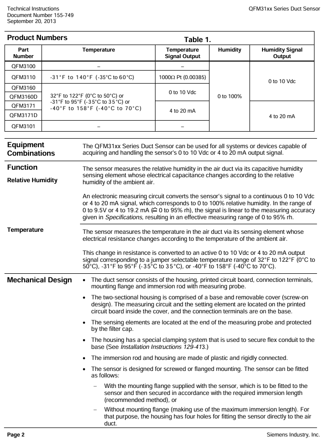
Covering sub models such as QFM3100 (basic version), QFM3160 (with display), QFM3171D (4-20mA output), etc., collectively referred to as the QFM31xx series, it provides high-precision measurement of air duct temperature and humidity.
2. Application scenarios
Sensors are suitable for ventilation and air conditioning systems with high requirements for temperature and humidity accuracy and response speed. Typical installation scenarios include:
Industrial scenarios: storage and production workshops in paper mills, textile factories, pharmaceutical factories, food factories, and electronic factories;
Special venues: laboratories, hospitals, computer data centers, indoor swimming pools, greenhouses;
Functional roles: Air supply/return control sensor, humidity limit sensor after steam humidifier, building automation system (BAS) access sensor.
Core technical characteristics of the product
1. Power supply and signal output
Category parameter content, key data
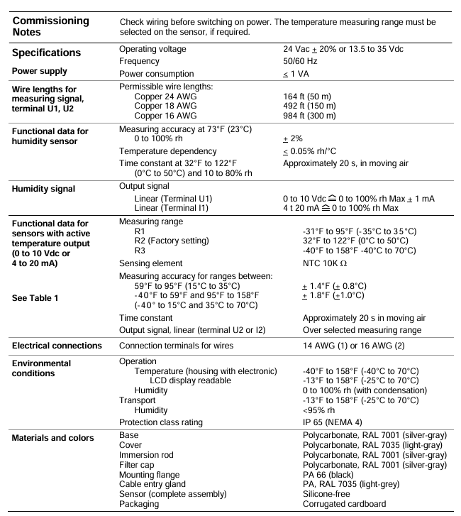
Supply voltage AC/DC dual compatible 24 Vac (± 20%, 50/60Hz); 13.5-35 Vdc
Low power consumption design<1 VA
Humidity output with two signal types: 0-10 Vdc (corresponding to 0-100% RH, maximum current 1mA); 4-20 mA (corresponding to 0-100% RH)
The temperature output range can be selected from 0-10 Vdc/4-20 mA, and the range can be selected through jumper wires (see Table 2)
Cable lengths are classified by wire diameter as 24 AWG (50m), 18 AWG (150m), and 16 AWG (300m)
2. Measurement performance (accuracy and response)
Measurement Type Accuracy Index Response Characteristics Remarks
± 2% RH at relative humidity of 23 ℃; temperature coefficient<0.05% RH/℃ Time constant of about 20s (in flowing air) Effective measurement range 0-95% RH (0-9.5V/4-19.2mA linear)
± 0.8 ℃ at a temperature of 15-35 ℃; -The time constant of ± 1.0 ℃ at 40-15 ℃/35-70 ℃ is about 20 seconds (in flowing air). The sensing element is NTC 10K Ω
3. Protection and environmental adaptability
Protection level: IP65 (NEMA 4), dustproof and water-resistant, suitable for humid air duct environments;
Work environment: Adapt to the air temperature inside the duct (consistent with the selected temperature range), humidity 0-100% RH;
Material compatibility: The shell is made of polycarbonate (impact resistant), the filter cap is made of the same material, and the overall silicon free design avoids polluting sensitive environments (such as electronic factories).
Mechanical Design and Installation Specification
1. Mechanical structure
Overall composition: consisting of a housing (base+detachable cover plate), a printed circuit board (PCB), wiring terminals, mounting flanges, and an immersion probe (including sensing elements and filter caps);
Shell design:
Base: Integrated wiring terminal and conduit clamping system (fixing flexible conduit), color RAL 7001 (silver gray);
Cover plate: Built in measurement circuit and jumper (range configuration), color RAL 7035 (light gray), fixed with screws;
Probe: Made of polycarbonate material (RAL 7001), the end sensing element is protected by a filter cap to prevent dust contamination.
2. Installation method and requirements
Key requirements for installation method and operation steps
Install flange (recommended) 1. Assemble the flange with the sensor; 2. Fix the flange to the air duct according to the required immersion length; 3. Insert the sensor and tighten it to adjust the immersion length as needed. The flange material is PA66 (black)
No installation flange 1. Use 4 mounting holes on the shell; 2. Directly screw the sensor onto the air duct using the maximum immersion length to ensure measurement representativeness
Special scenario (dew point offset) 1. Only fix the flange to the air duct wall; 2. Insert the sensor from the flange and clamp it tightly. It must be installed in the return air duct to avoid measurement deviation
Installation taboos:
Avoid probe impact: Sensing components are easily damaged by impact and should be handled gently during installation;
Distance between steam humidifiers: The minimum distance from the humidifier should be ≥ 3m (recommended ≤ 10m) to prevent sudden humidity changes from affecting accuracy;
Sealing protection: It is forbidden to remove the seal between the shell and the cover plate to prevent water vapor from entering and damaging the circuit.
Parameter configuration and debugging
1. Jumper configuration (on PCB, under cover)
The jumper has 6 pins and 1 jumper cap, which is used to select temperature range, display unit, and activate testing functions. The specific configuration is as follows:
Configure the parameters corresponding to the jumper position of the configuration function
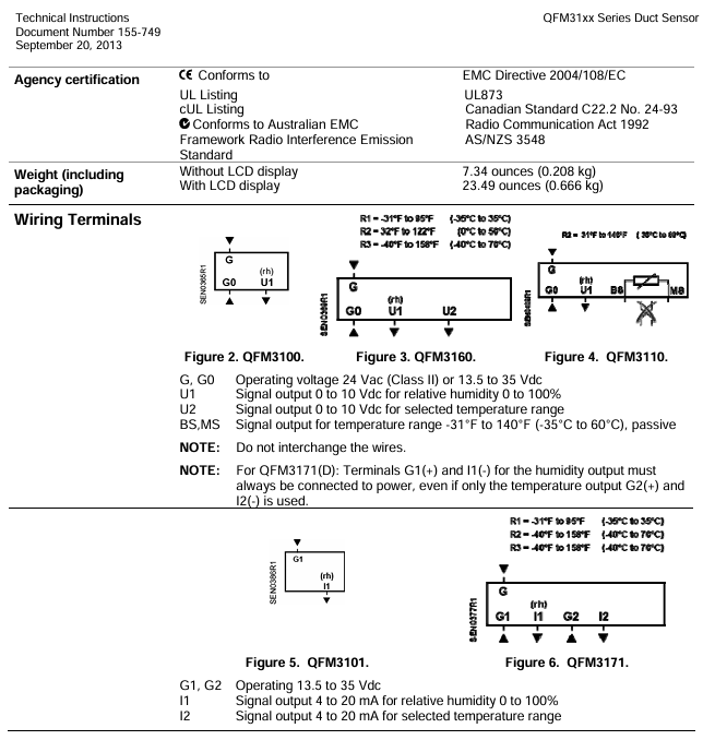
Temperature range selection left (1) -31 ° F~95 ° F (-35 ℃~35 ℃)
Right position (3) -40 ° F~158 ° F (-40 ℃~70 ℃)
Display unit selection (with LCD model) vertical right position Celsius (℃, factory default)
Vertical left Fahrenheit (℉)
Test function activation level signal output specific values (such as 0V/10V, 4mA/20mA) for troubleshooting
2. Debugging steps
Wiring inspection: Confirm that the power and signal lines are connected correctly (refer to the terminal definition in Figure 2-6, for example, QFM3171 needs to ensure that G1/I1 is powered on, even if only temperature output is used);
Range configuration: According to on-site requirements, set the temperature range and display unit through jumper wires;
Power on verification: Connect the power supply and check if the output signal (humidity 0-10V/4-20mA, temperature corresponding range signal) is normal. For models with LCD, it is necessary to confirm the alternating display of temperature and humidity (5-second interval).
Fault diagnosis and spare parts
1. Fault diagnosis (output characteristics when sensor failure occurs)
Fault type: Humidity signal output (U1/I1) Temperature signal output (U2/I2) Remarks
Temperature sensor fault rises to 10V (0-10V output) or corresponding 20mA (4-20mA output) drops to 0V (0-10V output) or corresponding 4mA (4-20mA output). The fault is immediately triggered
The humidity sensor malfunctions for 60 seconds and then rises to 10V/20mA to maintain normal output with a delay of 60 seconds, making it easier for the system to identify
2. Spare parts list (for replacement)
Spare part model, spare part name, and purpose
The AQF3101 filter cap protects the sensing elements inside the probe, preventing dust from entering
Replace damaged temperature and humidity sensing components with AQF3150 sensing head
74 662 01040 1/2 inch rigid conduit adapter for connecting conduit to sensor base
Compliance and physical specifications
1. Certification and Standards
Compliance Directive: Complies with EMC Directive 2004/108/EC (Electromagnetic Compatibility) and AS/NZS 3548 (Radio Interference Emission Framework Standard);
Electrical specifications: The power supply requires the use of a Class II transformer (independent winding, 100% duty cycle), and the selection should consider sensor power consumption and local electrical regulations.
2. Physical specifications
Project specification parameters
Material base/probe: polycarbonate (RAL 7001); Cover plate: polycarbonate (RAL 7035); Flange: PA66 (black)
Protection level IP65 (NEMA 4)
Weight (including packaging) without LCD display: 7.34 ounces (0.208kg); With LCD display: 23.49 ounces (0.666kg)
The wiring terminal is compatible with 14 AWG (1 way) or 16 AWG (2 ways) wires
Engineering precautions
Power selection: Class II transformers must be used with independent winding design to ensure safe isolation;
Cable selection: Shielded twisted pair cables are required for EMC interference environments, and secondary power lines and signal lines need to be twisted to reduce interference;
Wiring specifications: Avoid long-distance parallel laying of cables (too small spacing can easily cause interference), strictly follow the allowed cable length (distinguished by wire diameter);
Maintenance requirements: Regularly check the cleanliness of the filter cap (contamination can affect response speed), and replace it promptly if it is damaged.
- YOKOGAWA
- Reliance
- ADVANCED
- SEW
- ProSoft
- WATLOW
- Kongsberg
- FANUC
- VSD
- DCS
- PLC
- man-machine
- Covid-19
- Energy and Gender
- Energy Access
- Renewable Integration
- Energy Subsidies
- Energy and Water
- Net zero emission
- Energy Security
- Critical Minerals
- A-B
- petroleum
- Mine scale
- Sewage treatment
- cement
- architecture
- Industrial information
- New energy
- Automobile market
- electricity
- Construction site
- HIMA
- ABB
- Rockwell
- Schneider Modicon
- Siemens
- xYCOM
- Yaskawa
- Woodward
- BOSCH Rexroth
- MOOG
- General Electric
- American NI
- Rolls-Royce
- CTI
- Honeywell
- EMERSON
- MAN
- GE
- TRICONEX
- Control Wave
- ALSTOM
- AMAT
- STUDER
- KONGSBERG
- MOTOROLA
- DANAHER MOTION
- Bentley
- Galil
- EATON
- MOLEX
- Triconex
- DEIF
- B&W
- ZYGO
- Aerotech
- DANFOSS
- KOLLMORGEN
- Beijer
- Endress+Hauser
- schneider
- Foxboro
- KB
- REXROTH
- YAMAHA
- Johnson
- Westinghouse
- WAGO
- TOSHIBA
- TEKTRONIX
- BENDER
- BMCM
- SMC
- HITACHI
- HIRSCHMANN
- XP POWER
- Baldor
- Meggitt
- SHINKAWA
- Other Brands
- UniOP
- KUKA
- IBA
- Beckhoff
-
LTI SC52.0040.0012.0000.0 - Servo Drive
-
Lti SC52.0040.0012.0000.0 - Servo Drive
-
Milton Industries LTI Tool By Milton LT1240 - 1/2" Drive Lugnut Remover
-
LTi Drives SO84.200.P030.0000.0-W - Servo Spindle Drive
-
LTI DRIVES LSP08-035-320-30-B0R1PY170 - Servo Motor
-
LTI DRIVES SE84.200.SC00.0001.0-W - Servo Drive
-
Lust CDE34.005.W2.2 - Lti Drives Controller
-
LTi SO84.012.0030.0011.2 - ServoOne Servo Drive
-
LTi Drives SO CM-P.0010.11.00.0 - Servo Drive Controller
-
LTi CDE34.017.W3.0 - Servo Drive
-
LTI Drives CDB32.004, C2.0,SH - Positioning Controller
-
LUST CM-CAN1 - LTi DRIVES Communication Module
-
LTi SO84.012.1030.0000.2 - Servo Drive
-
LTI MOOG CDE54.044 - PITCHMASTER FREQUENCY CONVERTER 181-01019
-
MOOG LTI 181-01019 CDE54.044 - PITCHMASTER FREQUENCY CONVERTER
-
Lust LTi Drives CDE34.010,D2.0 - Servo Drive Controller
-
LTI SO84.032.0003.0101.2 - Servo Drive
-
Seagate 9CC132-302 Harris LTI-CS IRT-34-0021-01 - Hard Drive 160GB
-
LTI SO84.032.0003.0001.2 - Servo Drive
-
LTI SO24.007.0070.0000.1 - SERVO CONTROLLER
-
LTi drive CDA32.003.C3.0.H05-01.PC1 - Servo Drive
-
LTI SO84.016.0030.0000.2 - SERVO CONTROLLER
-
LUST LTI CD A34.008,W1.4, BR - SERVO DRIVE
-
MOOG LTI 181-01019 CDE54.044 - PITCHMASTER FREQUENCY CONVERTER
-
LTI MOOG 181-01019 - PITCH Master Servo Drive CDE54.044
-
LTI SERVO ONE SO84.045.0030.0001.2-W - Drive
-
LUST LTi SO84.032.0040.0000.2 - SERVO ONE DRIVE
-
LTi Drives LSH-074-2-30-3 20/T1,G6.1M - SERVO MOTOR
-
LTI SO84.016.0000.0101.2 - servo drive
-
LTI SA54.0550.0033.0000.0 - Servo Drive
-
LTI SA54.0550.0033.0000.0 - Servo Drive
-
LTI LT 4850 - 3/8" Drive 3-Pc Twist Socket Transmission Drain Plug Removal System
-
LTI Tools LT4400-30 Lock Technology - 3/4" Twist Socket 1/2" Drive Lugnut Remover
-
LTI Tools LT-1400C - 1/2 Drive Wheel Torque Extension Tool
-
LTI Tools LT1250 - 1/2" Drive Dual Sided Socket Lug Nut Remover Tool
-
LTI SO84.032.0003.0101.2 - Servo Drive
-
LTI MOOG 181-01019 - PITCH Master Servo Drive CDE54.044
-
MOOG LTI 181-01019 CDE54.044 - PITCHMASTER FREQUENCY CONVERTER
-
MOOG LTI 181-01019 CDE54.044 - PITCHMASTER FREQUENCY CONVERTER
-
MOOG LTI 181-01019 CDE54.044 - PITCHMASTER FREQUENCY CONVERTER
-
LTI SA54.0550.0033.0000.0 - Servo Drive
-
LTI Tools LT-4800 - 7 Piece Twist Socket 3/8" Drive Oil Drain Plug Removal Set
-
LTI SA54.0550.0033.0000.0 - Servo Drive
-
LTI Drive SO24.007.00300000.0 - Servo Drive
-
LTI TOOLS LTI 1400-I - Drive Wheel Torque Extension
-
LTI Tools LT4400-3 - 3/4" 19mm Twist Socket 1/2" Drive Lugnut
-
LTI TOOLS LTI 1400-BB - Drive Wheel Torque Extension
-
LTI SO84.032.0003.0101.2 - Servo Drive
-
LTI Tools LT-4512 - 3/8" Drive 12mm Twist Socket
-
LTI MOTION Luster SO84.032.0003.0001.2 - Servo Drive
-
LTI Tool By Milton LT1600P - 1" Drive Torx Stick
-
LTI Lust VF1424L,HF,OP2,S56 - Variable Frequency Drive
-
LUST CDA32.004,C1.4,H08,B0 - SERVO DFRIVE CM-CAN1 Module
-
LTI SO84.045.0002.0001.2-W - Drive
-
LTI Lust VF1404M,C9,PT1,BR1 - Inverter Type VF1404M
-
LTI SA54.0550.0033.0000.0 - Servo Drive
-
LTI Tools LT-1400C - 1/2" Drive Wheel Torque Extension
-
Lust LTI DRiVES CDA32.006, C3.0, H09 - Variateur De Fr茅quence Frequency Inverter
-
LTI MOOG CDE54.044 - PITCH master SERVO DRIVE
-
LTI MOOG CDE54.044 - PITCH master SERVO DRIVE
-
LTI SO84.143.0020.0101.2-W - servo drive
-
LTI MOTION SC34.0200.0011.0000.0 - Servo drives
-
LTI SO84.032.0003.0001.2 - Servo Drive
-
LTI DRIVES GmbH MS100 - Assembly Set Mounting Kit
-
LTI SO84.032.0003.0001.2 - Servo Drive
-
LTI SO84.032.0003.0001.2 - Servo Drive
-
LTI MOTION SO84.032.0003.0101.2 - servo drive
-
LTI SO84.032.0003.0101.2 - Servo Drive
-
LTI MOOG CDE54.044 - PITCH master SERVO DRIVE
-
LTI MOTION CDE32.004.C2.4 - Servo drives
-
LTI CDD34.032锛學x.x锛孊R锛孭C1 - Servo Drive
-
Lust LTI DRiVES CDA32.006, C3.0, H09 - Inversor De Frecuencia Frequency Inverter
-
Lust SO84.008.0030.1000.0 - Servo One LTi Drive
-
LTI MOTION SO84.032.0003.0101.2 - Servo drives
-
LUST LTi CDA32.004,C1.4 - SERVO DRIVE
-
LTI MOOG CDE54.044 - PITCH Master SERVO DRIVE
-
LTI KEBA CDB32.004 C2.7, SH - PN: 08673530 Frequency Inverter
-
LTI Tools LT-1400C - 1/2" Drive Wheel Torque Extension
-
LTI LT1400-E - 1/2" Drive Wheel Torque Extension
-
LTI MOOG 181-01019 - PITCH master SERVO DRIVE CDE54.044
-
LTI LSN-097-0510-30-560/T1 - Actuator Motor
-
LTI Tools LT 4800 - 7 Piece 3/8" Drive Twist Socket Oil Drain Plug Removal System
-
LTI DRIVES GmbH MS100 - MONTAGESET Assembly Set Mounting Kit
-
Lti SC52.0040.0012.0000.0 - Servo Drive
-
LTI DRIVES GmbH MS100 - Juego De Montaje Assembly Set Mounting Kit
-
LTi DSM4-14.2-21R83-200 - Drives servomoteur Servo Motor
-
MOOG CDE 54.044.GDA - Pitch Master Industrielle Turbine Lti Drive
-
LTI SO24.004.0030.1000.0 - Servo Drive Controller
-
Lti MOOG CDE54.044 - Pitch Master Servo Drive
-
Lust LTI DRiVES CDA32.006, C3.0, H09 - Inverter
-
LTI MOTION GMBH CDB34.006,W3.0,PC1,H39 - Frequency inverter
-
LTI SO84.032.0003.0001.2 - Servo Drive
-
MOOG CDE 54.044.D - Pitch Master Industrielle Turbine Lti Drive
-
LTI TOOLS LT-1460 - 1/2" DRIVE WHEEL TORQUE EXTENSION KIT 5 PIECE SET
-
Lust Cdb32.003, C2.4 - Lti Drives Servoregulador Frecuencia Servo Controller Inverter
-
Lust LTI DRIVES CDA32.006, C3.0, H09 - Frequency Inverter
-
Lust Lti SO82.004.0030.0000.2 - Servo Drive
-
LTI MOTION SC34.0200.0011.0000.0-SL - Servo drives
-
LTI MOTION SA54.0075.0033.0000.0 - Servo drives
-
LTI MOTION SC32.0075.1011.0000.0 - Servo drives
-
Lust Cdb32.003, C2.4 - Lti Drives Servo Controller Frequency Inverter
-
LTI MOOG CDE54.044 - PITCH master SERVO DRIVE
-
Lust Lti Cde34.006,W2.0,Br - Servo Drive
-
Lust LTi MOTION CDE34.044,W2.4,H13 - Servo Drive
-
Lust LTi Drives Cde32.008, W2.2.br - Positionierregler Posici贸n Mando Positioning Controller
-
LTI MOOG CDE54.044 - PITCH master SERVO DRIVE
-
LUST Antriebstechnik B-DS 125.1 - LTi DRiVES Accessories Drive Component
-
LTi LSMM13-100-4N-001 - servo motor
-
Lti CDA32.004 C1.4, H08, B0 - PN: 3084456 Frequency Inverter
-
LTI MOTION CDE34.006.WXX.PC1 - Servo drives
-
LTI MOTION SO24.007.0030.1000.0 - Servo drives
-
Lust CDD34.005.C2.1 - LTI Drive
-
Lti SC52.0040.0012.0000.0 - Servo Drive
-
LTI Tools LT4400-30 - 1/2" Drive 19mm 3/4" Twist Socket
-
Lust LTi Drives Cde32.008, W2.2.br - Positionierregler Posici贸n Mando Positioning Controller
-
LTI MOOG CDE54.044 - PITCH master SERVO DRIVE
-
LUST Antriebstechnik B-DS 125.1 - LTi DRiVES Accessories Drive Component
-
LTI DRIVES GmbH MS100 - MONTAGESET Assembly Set Mounting Kit
-
Lust LTi SO84.032.0043.0000.2 - Servo one Drive
-
LUST LTi Drives CM-CAN1 - Modulo Di Comunicazione Communication Module
-
LTI drive CDF 30.008.C3.6 - Servo Drive
-
LTI MOOG 181-01019 - PITCH master SERVO DRIVE
-
LTI CDB34.014,W2.4,BR,SH - Servo Driver
-
Lti SC52.0040.0012.0000.0 - Servo Drive
-
LTi Drive CDF30.002 - Power Supply Fuse
-
LTI Tools LT-4621-D - Deep Well Twist Socket 3/8" Drive 1/2"
-
LTI MOOG PITCH master CDE54.044 - SERVO DRIVE Frequency Converter
-
LTI SO84.076.S030.0001.2-W - Servo One Drive

K-JIANG

Add: Jimei North Road, Jimei District, Xiamen, Fujian, China
Tell:+86-15305925923