
K-WANG


SIEMENS SIMOTICS SD 1LE7 series low-voltage motor (shaft height 71-315)
SIEMENS SIMOTICS SD 1LE7 series low-voltage motor (shaft height 71-315)
Product positioning: Three phase asynchronous induction motor, with a shaft height coverage of 71-315mm, available in self ventilated (IC411) and forced ventilated (IC416) versions, suitable for industrial drive scenarios, supporting direct grid operation (50/60Hz) and variable frequency drive (such as SINAMICS G/S series).
Typical applications: Industrial equipment such as fans, pumps, compressors, and conveyors, suitable for continuous and intermittent operation.
Safety warning system (core emphasis)
1. Risk grading standards
Adopting a four level risk warning system to clarify the level of risk and response requirements, with a focus on electric shock and injuries to rotating parts
Warning level identification, risk description, typical scenarios
DANGER red safety symbol. Failure to protect may result in death/serious injury. Contact with live parts and rotor falling (when installed vertically)
Warning: The red safety symbol does not provide protection and may cause death/serious injury. Contact with rotating parts and burns on high-temperature surfaces
CAUTION yellow safety symbol may cause minor injury if not protected. Foreign objects may splash during compressed air cleaning
NOTICE unsigned and unprotected may cause property damage, cable shielding errors, and loose bolts
2. Special hazard prevention and control
Electric shock hazard:
Risk: When live parts are exposed, the contact voltage can be fatal, and there may still be residual voltage of ≥ 60V at the terminals after power failure;
Prevention and control: Strictly follow the "5 safety rules" (power-off → anti misoperation → electricity inspection → grounding → protection of adjacent live parts), and match the PE wire cross-section with the phase wire (PE=S when S ≤ 25mm ², PE=0.5S when S>50mm ²).
Danger of rotating parts:
Risk: unprotected rotating components such as fans and couplings can easily cause entanglement injuries;
Prevention and control: It is necessary to install a protective cover. After stopping the machine, wait for the rotor to come to a complete stop (≥ 5 minutes) before removing the protective cover.
High temperature hazard:
Risk: The temperature of the winding/bearing during motor operation may exceed 100 ℃, and the temperature may further increase during anti condensation heating operation;
Prevention and control: Stick a "hot surface" label, cool for at least 30 minutes before maintenance, and interlock the anti condensation heating with the main motor (heating is turned off when the motor is running).
Product Core Features
1. Structure and composition
Component Function Description Key Parameters/Requirements
The stator contains three-phase windings and provides magnetic field insulation level Class 155 (F level). The winding temperature monitoring can be selected from PTC/KTY84/Pt1000
The rotor induced current generates torque dynamic balance level A (optional level B), and the balance methods are divided into "H" (half key), "F" (full key), and "N" (no key)
Bearing supports the rotor, transmits radial/axial force through rolling bearings, with a shaft height of ≤ 200 for permanent lubrication, ≥ 225 with M10 oil injection nozzle, and a design life of ≥ 50000 hours (horizontal coupling)
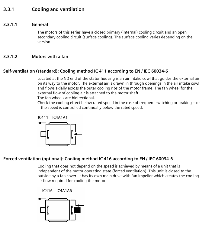
Cooling system export loss heat self ventilation IC411 (standard, fan installed at the shaft end), forced ventilation IC416 (optional, independently driven fan)
The electrical connection interface of the terminal box can rotate 4 × 90 °, with a protection level of IP65, and the cable entry is compatible with M16-M63 cable glass
2. Key technical parameters
Environmental adaptability:
Operating temperature: -20~+50 ℃ (beyond which capacity reduction is required);
Installation altitude: ≤ 1000m (power reduction of 10% for every 1000m above sea level);
Humidity: ≤ 60% (no condensation), condensation environment requires optional anti condensation heating (power ≤ 50W).
Electrical performance:
Voltage range: Complies with IEC 60034-1 Zone A (voltage fluctuation ± 5%, frequency fluctuation ± 2%);
Insulation resistance: New motor ≥ 100M Ω, during operation ≥ 30M Ω (500V DC test);
Bearing current protection: Insulated bearings (NDE end) can be selected when driving the frequency converter, and EMC grounding (shielded cable double end grounding) is required.
Vibration and noise:
Vibration level: Standard A (compliant with ISO 10816-3), optional B level;
Noise emissions: ≤ 70dB (A) (at rated power), textile industry specific motors require regular cleaning of fan cover fluff.
Full lifecycle operating standards
1. Transportation and Storage
Transportation requirements:
Packaging: Wooden packaging complies with ISPM 15 and is labeled with "Fragile", "Moisture proof", and "This Side Up" signs;
Lifting: Use the motor's built-in lifting ring (with M16 lifting ring for shaft height ≥ 180), with a 2-point lifting angle ≤ 45 °. Single motor lifting of the unit is prohibited.
Storage requirements:
Environment: Indoor dry, dust-free, vibration free, temperature -20~+50 ℃, humidity ≤ 60%;
Protection: Apply rust inhibitor (such as Tectyl) to the shaft end/flange surface. For long-term storage (>12 months), rotate the rotor monthly (to avoid bearing indentation), drain the cooling system, and lock the interface;
Rotor fixing: During transportation, rotor fixing components need to be installed, and vertically installed motors need to be stored in a vertical position.
2. Mechanical installation
General rules:
Bolt: Only use new bolts of grade 8.8 or above, with no oil/paint on the fixing surface and a surface roughness of Rz 10-40 μ m;
Tightening torque: M5=5Nm, M6=8Nm, M8=20Nm, M10=40Nm, optional Loctite 243 anti loosening.
Installation in different scenarios:
Horizontal foot installation (IM B3): Adjust the levelness with shims, with a support surface flatness of ≤ 0.2mm (shaft height ≥ 180);
Flange installation (IM B5): The flange centering surface is coated with paste, and the bolts are pre tightened in a 120 ° distribution, and finally tightened in diagonal order;
Vertical installation (IM V1): The rotor needs to be supported (to avoid bearing overload), and a protective cover should be added when the shaft end is facing downwards (to prevent foreign objects from falling in).
Alignment requirements:
Speed (rpm) Parallel deviation (mm) Angular deviation (mm/100mm Coupling diameter)
750 0.09 0.09
1500 0.06 0.05
3000 0.03 0.025
3. Electrical connection
Safety requirements:
Power supply: Only connect to the matching frequency converter or power grid, and do not directly connect to the three-phase AC power grid (frequency converter drives the motor);
Grounding: The PE wire is directly connected to the power module, and the grounding terminal inside the terminal box needs to be fastened with M5 bolts (torque 1.8-2.5Nm).
Specific connection:
Power cable: 4-core (PE=green yellow, U=black, V=black, W=black), core wire cross-section selected according to rated current (2.5mm ² corresponds to 21A, 16mm ² corresponds to 66A);
Control cable: The temperature sensor/anti condensation heating cable needs to be wired separately from the power cable, and the shielding layer should be grounded at one end;
Terminal marking: According to EN/IEC 60034-8, U/V/W corresponds to L1/L2/L3, and swapping any two phases can change the direction of rotation.
4. Debugging
Debugging premise:
Mechanical: Complete installation alignment, manually rotate the rotor without any obstruction;
Electrical: Insulation resistance ≥ 30M Ω, reliable PE grounding, cable gland tightened (M20 gland torque 12Nm).
Key steps:
No load test run: Power on and run for 5 minutes, check the steering (clockwise is U-V-W phase sequence) and vibration (≤ 4.5mm/s);
Load trial operation: gradually load to rated load, monitor current (≤ rated current), bearing temperature (≤ 115 ℃ alarm, ≤ 120 ℃ shutdown);
Variable frequency drive debugging: Parameterize the variable frequency drive (input motor rated current, speed, number of poles), set the avoidance frequency (38-48Hz, shaft height 315 two pole motor).
5. Operation and maintenance
Operation monitoring:
Normal parameters: current ≤ rated value, bearing temperature ≤ 90 ℃, vibration ≤ 4.5mm/s;
Troubleshooting: Motor cannot start (check for overload/phase loss), overheating (check for cooling/load), abnormal noise (check for bearings/alignment), please refer to the fault table for details.
Maintenance cycle:
Maintain project cycle content
Initial inspection: 500 operating hours/6 months. Check bolt tightness, bearing temperature, and insulation resistance
Regularly inspect 16000 operating hours/2 years, clean the cooling air duct, grease (with oil nozzle bearings), and check the grounding
Bearing replacement: 50000 operating hours (horizontal)/20000 hours (vertical). Replace bearings and shaft seals, clean the bearing chamber
Insulation testing measures insulation resistance (≥ 30M Ω) and polarization index (≥ 2) every year/after shutdown for more than 3 months
6. Scrapping and disposal
Scrap steps:
Power off → wait for capacitor discharge → cool down for 30 minutes;
Dismantle the cable and drain the coolant (compliant treatment);
Remove the fixing bolts of the motor and disassemble it in reverse order (first remove the fan cover, then remove the end cover).
Waste disposal:
Metal components: classified recycling of steel, aluminum, and copper (winding copper can be melted and recycled);
Insulation material: incineration (in compliance with environmental requirements);
Hazardous substance: Lead (CAS 7439-92-1, content ≤ 0.1%) must be disposed of in accordance with the REACH directive, and packaging materials (PE/PP) are recyclable.
Appendix and Compliance
1. Key Appendix Resources
Spare parts list: including end caps (1.40), bearings (1.60), cable glass (5.03), fans (7.04) and other spare parts models and explosion diagrams;
Tightening torque table: specify the tightening torque for different thread specifications (such as M12 bolt 70Nm, M16 cable glass 170Nm);
Terminal box dimensions: Axis height 71-90 Terminal box TB7 D04 (dimensions A=89mm, B=111mm), Axis height 250-280 Terminal box TB1 NO1 (dimensions A=233mm, B=319mm).
2. Compliance standards
Following standards: EN/IEC 60034 (Rotating Electrical Machinery), EN/IEC 60204-1 (Mechanical and Electrical Equipment), EMC 2014/30/EU (Electromagnetic Compatibility);
Environmental directives: RoHS (Restriction of Hazardous Substances), REACH (Control of Substances of Very High Concern, such as Lead Content ≤ 0.1%)
- YOKOGAWA
- Reliance
- ADVANCED
- SEW
- ProSoft
- WATLOW
- Kongsberg
- FANUC
- VSD
- DCS
- PLC
- man-machine
- Covid-19
- Energy and Gender
- Energy Access
- Renewable Integration
- Energy Subsidies
- Energy and Water
- Net zero emission
- Energy Security
- Critical Minerals
- A-B
- petroleum
- Mine scale
- Sewage treatment
- cement
- architecture
- Industrial information
- New energy
- Automobile market
- electricity
- Construction site
- HIMA
- ABB
- Rockwell
- Schneider Modicon
- Siemens
- xYCOM
- Yaskawa
- Woodward
- BOSCH Rexroth
- MOOG
- General Electric
- American NI
- Rolls-Royce
- CTI
- Honeywell
- EMERSON
- MAN
- GE
- TRICONEX
- Control Wave
- ALSTOM
- AMAT
- STUDER
- KONGSBERG
- MOTOROLA
- DANAHER MOTION
- Bentley
- Galil
- EATON
- MOLEX
- Triconex
- DEIF
- B&W
- ZYGO
- Aerotech
- DANFOSS
- KOLLMORGEN
- Beijer
- Endress+Hauser
- schneider
- Foxboro
- KB
- REXROTH
- YAMAHA
- Johnson
- Westinghouse
- WAGO
- TOSHIBA
- TEKTRONIX
- BENDER
- BMCM
- SMC
- HITACHI
- HIRSCHMANN
- XP POWER
- Baldor
- Meggitt
- SHINKAWA
- Other Brands
- UniOP
- KUKA
- IBA
- Beckhoff
-
LTI SC52.0040.0012.0000.0 - Servo Drive
-
Lti SC52.0040.0012.0000.0 - Servo Drive
-
Milton Industries LTI Tool By Milton LT1240 - 1/2" Drive Lugnut Remover
-
LTi Drives SO84.200.P030.0000.0-W - Servo Spindle Drive
-
LTI DRIVES LSP08-035-320-30-B0R1PY170 - Servo Motor
-
LTI DRIVES SE84.200.SC00.0001.0-W - Servo Drive
-
Lust CDE34.005.W2.2 - Lti Drives Controller
-
LTi SO84.012.0030.0011.2 - ServoOne Servo Drive
-
LTi Drives SO CM-P.0010.11.00.0 - Servo Drive Controller
-
LTi CDE34.017.W3.0 - Servo Drive
-
LTI Drives CDB32.004, C2.0,SH - Positioning Controller
-
LUST CM-CAN1 - LTi DRIVES Communication Module
-
LTi SO84.012.1030.0000.2 - Servo Drive
-
LTI MOOG CDE54.044 - PITCHMASTER FREQUENCY CONVERTER 181-01019
-
MOOG LTI 181-01019 CDE54.044 - PITCHMASTER FREQUENCY CONVERTER
-
Lust LTi Drives CDE34.010,D2.0 - Servo Drive Controller
-
LTI SO84.032.0003.0101.2 - Servo Drive
-
Seagate 9CC132-302 Harris LTI-CS IRT-34-0021-01 - Hard Drive 160GB
-
LTI SO84.032.0003.0001.2 - Servo Drive
-
LTI SO24.007.0070.0000.1 - SERVO CONTROLLER
-
LTi drive CDA32.003.C3.0.H05-01.PC1 - Servo Drive
-
LTI SO84.016.0030.0000.2 - SERVO CONTROLLER
-
LUST LTI CD A34.008,W1.4, BR - SERVO DRIVE
-
MOOG LTI 181-01019 CDE54.044 - PITCHMASTER FREQUENCY CONVERTER
-
LTI MOOG 181-01019 - PITCH Master Servo Drive CDE54.044
-
LTI SERVO ONE SO84.045.0030.0001.2-W - Drive
-
LUST LTi SO84.032.0040.0000.2 - SERVO ONE DRIVE
-
LTi Drives LSH-074-2-30-3 20/T1,G6.1M - SERVO MOTOR
-
LTI SO84.016.0000.0101.2 - servo drive
-
LTI SA54.0550.0033.0000.0 - Servo Drive
-
LTI SA54.0550.0033.0000.0 - Servo Drive
-
LTI LT 4850 - 3/8" Drive 3-Pc Twist Socket Transmission Drain Plug Removal System
-
LTI Tools LT4400-30 Lock Technology - 3/4" Twist Socket 1/2" Drive Lugnut Remover
-
LTI Tools LT-1400C - 1/2 Drive Wheel Torque Extension Tool
-
LTI Tools LT1250 - 1/2" Drive Dual Sided Socket Lug Nut Remover Tool
-
LTI SO84.032.0003.0101.2 - Servo Drive
-
LTI MOOG 181-01019 - PITCH Master Servo Drive CDE54.044
-
MOOG LTI 181-01019 CDE54.044 - PITCHMASTER FREQUENCY CONVERTER
-
MOOG LTI 181-01019 CDE54.044 - PITCHMASTER FREQUENCY CONVERTER
-
MOOG LTI 181-01019 CDE54.044 - PITCHMASTER FREQUENCY CONVERTER
-
LTI SA54.0550.0033.0000.0 - Servo Drive
-
LTI Tools LT-4800 - 7 Piece Twist Socket 3/8" Drive Oil Drain Plug Removal Set
-
LTI SA54.0550.0033.0000.0 - Servo Drive
-
LTI Drive SO24.007.00300000.0 - Servo Drive
-
LTI TOOLS LTI 1400-I - Drive Wheel Torque Extension
-
LTI Tools LT4400-3 - 3/4" 19mm Twist Socket 1/2" Drive Lugnut
-
LTI TOOLS LTI 1400-BB - Drive Wheel Torque Extension
-
LTI SO84.032.0003.0101.2 - Servo Drive
-
LTI Tools LT-4512 - 3/8" Drive 12mm Twist Socket
-
LTI MOTION Luster SO84.032.0003.0001.2 - Servo Drive
-
LTI Tool By Milton LT1600P - 1" Drive Torx Stick
-
LTI Lust VF1424L,HF,OP2,S56 - Variable Frequency Drive
-
LUST CDA32.004,C1.4,H08,B0 - SERVO DFRIVE CM-CAN1 Module
-
LTI SO84.045.0002.0001.2-W - Drive
-
LTI Lust VF1404M,C9,PT1,BR1 - Inverter Type VF1404M
-
LTI SA54.0550.0033.0000.0 - Servo Drive
-
LTI Tools LT-1400C - 1/2" Drive Wheel Torque Extension
-
Lust LTI DRiVES CDA32.006, C3.0, H09 - Variateur De Fr茅quence Frequency Inverter
-
LTI MOOG CDE54.044 - PITCH master SERVO DRIVE
-
LTI MOOG CDE54.044 - PITCH master SERVO DRIVE
-
LTI SO84.143.0020.0101.2-W - servo drive
-
LTI MOTION SC34.0200.0011.0000.0 - Servo drives
-
LTI SO84.032.0003.0001.2 - Servo Drive
-
LTI DRIVES GmbH MS100 - Assembly Set Mounting Kit
-
LTI SO84.032.0003.0001.2 - Servo Drive
-
LTI SO84.032.0003.0001.2 - Servo Drive
-
LTI MOTION SO84.032.0003.0101.2 - servo drive
-
LTI SO84.032.0003.0101.2 - Servo Drive
-
LTI MOOG CDE54.044 - PITCH master SERVO DRIVE
-
LTI MOTION CDE32.004.C2.4 - Servo drives
-
LTI CDD34.032锛學x.x锛孊R锛孭C1 - Servo Drive
-
Lust LTI DRiVES CDA32.006, C3.0, H09 - Inversor De Frecuencia Frequency Inverter
-
Lust SO84.008.0030.1000.0 - Servo One LTi Drive
-
LTI MOTION SO84.032.0003.0101.2 - Servo drives
-
LUST LTi CDA32.004,C1.4 - SERVO DRIVE
-
LTI MOOG CDE54.044 - PITCH Master SERVO DRIVE
-
LTI KEBA CDB32.004 C2.7, SH - PN: 08673530 Frequency Inverter
-
LTI Tools LT-1400C - 1/2" Drive Wheel Torque Extension
-
LTI LT1400-E - 1/2" Drive Wheel Torque Extension
-
LTI MOOG 181-01019 - PITCH master SERVO DRIVE CDE54.044
-
LTI LSN-097-0510-30-560/T1 - Actuator Motor
-
LTI Tools LT 4800 - 7 Piece 3/8" Drive Twist Socket Oil Drain Plug Removal System
-
LTI DRIVES GmbH MS100 - MONTAGESET Assembly Set Mounting Kit
-
Lti SC52.0040.0012.0000.0 - Servo Drive
-
LTI DRIVES GmbH MS100 - Juego De Montaje Assembly Set Mounting Kit
-
LTi DSM4-14.2-21R83-200 - Drives servomoteur Servo Motor
-
MOOG CDE 54.044.GDA - Pitch Master Industrielle Turbine Lti Drive
-
LTI SO24.004.0030.1000.0 - Servo Drive Controller
-
Lti MOOG CDE54.044 - Pitch Master Servo Drive
-
Lust LTI DRiVES CDA32.006, C3.0, H09 - Inverter
-
LTI MOTION GMBH CDB34.006,W3.0,PC1,H39 - Frequency inverter
-
LTI SO84.032.0003.0001.2 - Servo Drive
-
MOOG CDE 54.044.D - Pitch Master Industrielle Turbine Lti Drive
-
LTI TOOLS LT-1460 - 1/2" DRIVE WHEEL TORQUE EXTENSION KIT 5 PIECE SET
-
Lust Cdb32.003, C2.4 - Lti Drives Servoregulador Frecuencia Servo Controller Inverter
-
Lust LTI DRIVES CDA32.006, C3.0, H09 - Frequency Inverter
-
Lust Lti SO82.004.0030.0000.2 - Servo Drive
-
LTI MOTION SC34.0200.0011.0000.0-SL - Servo drives
-
LTI MOTION SA54.0075.0033.0000.0 - Servo drives
-
LTI MOTION SC32.0075.1011.0000.0 - Servo drives
-
Lust Cdb32.003, C2.4 - Lti Drives Servo Controller Frequency Inverter
-
LTI MOOG CDE54.044 - PITCH master SERVO DRIVE
-
Lust Lti Cde34.006,W2.0,Br - Servo Drive
-
Lust LTi MOTION CDE34.044,W2.4,H13 - Servo Drive
-
Lust LTi Drives Cde32.008, W2.2.br - Positionierregler Posici贸n Mando Positioning Controller
-
LTI MOOG CDE54.044 - PITCH master SERVO DRIVE
-
LUST Antriebstechnik B-DS 125.1 - LTi DRiVES Accessories Drive Component
-
LTi LSMM13-100-4N-001 - servo motor
-
Lti CDA32.004 C1.4, H08, B0 - PN: 3084456 Frequency Inverter
-
LTI MOTION CDE34.006.WXX.PC1 - Servo drives
-
LTI MOTION SO24.007.0030.1000.0 - Servo drives
-
Lust CDD34.005.C2.1 - LTI Drive
-
Lti SC52.0040.0012.0000.0 - Servo Drive
-
LTI Tools LT4400-30 - 1/2" Drive 19mm 3/4" Twist Socket
-
Lust LTi Drives Cde32.008, W2.2.br - Positionierregler Posici贸n Mando Positioning Controller
-
LTI MOOG CDE54.044 - PITCH master SERVO DRIVE
-
LUST Antriebstechnik B-DS 125.1 - LTi DRiVES Accessories Drive Component
-
LTI DRIVES GmbH MS100 - MONTAGESET Assembly Set Mounting Kit
-
Lust LTi SO84.032.0043.0000.2 - Servo one Drive
-
LUST LTi Drives CM-CAN1 - Modulo Di Comunicazione Communication Module
-
LTI drive CDF 30.008.C3.6 - Servo Drive
-
LTI MOOG 181-01019 - PITCH master SERVO DRIVE
-
LTI CDB34.014,W2.4,BR,SH - Servo Driver
-
Lti SC52.0040.0012.0000.0 - Servo Drive
-
LTi Drive CDF30.002 - Power Supply Fuse
-
LTI Tools LT-4621-D - Deep Well Twist Socket 3/8" Drive 1/2"
-
LTI MOOG PITCH master CDE54.044 - SERVO DRIVE Frequency Converter
-
LTI SO84.076.S030.0001.2-W - Servo One Drive

K-JIANG

Add: Jimei North Road, Jimei District, Xiamen, Fujian, China
Tell:+86-15305925923