
K-WANG


REXROTH EcoDrive Cs series AC servo drive system
REXROTH EcoDrive Cs series AC servo drive system
The REXROTH EcoDrive Cs series AC servo drive system is a low-power drive solution covering a power range of 100~750 W. It includes a DKC series drive controller (supporting multiple buses such as PROFIBUS DP/CANopen) and an MSM series servo motor (IP65 protection, optional brake/absolute encoder), suitable for single/three-phase power supply of 200~240 V, supporting position/speed closed-loop control, with IP20 (controller)/IP65 (motor) protection level, suitable for industrial scenarios such as handling, packaging, and machine tools. The system needs to be built with dedicated cables and accessories, and installation and commissioning must comply with EMC and safety regulations.
Product Overview
System composition: EcoDrive Cs is a low-power AC servo drive system launched by Bosch Rexroth, consisting of DKC series drive controller and MSM series permanent magnet synchronous servo motor, matched with dedicated cables, braking resistors, encoders and other accessories, forming a complete drive solution.
Core positioning: Targeting power requirements of 100~750 W, suitable for single axis or multi axis industrial equipment, achieving precise position and speed closed-loop control, it is the core driving component for handling, packaging, machine tools and other scenarios.
Core strengths
Bus compatibility: Supports various industrial buses such as PROFIBUS DP, CANopen, DeviceNet, SERCOS, etc., and is compatible with multiple brands of control systems.
Flexible configuration: The motor can be equipped with optional brake, incremental/absolute encoder, optical axis/key axis, and the controller supports expansion modules.
Safe and reliable: Complies with EN 50178 safety standards, with overvoltage, overload, emergency stop protection, and leakage current protection.
Easy installation: The controller supports rail installation, the motor is compatible with multiple installation postures, and the cable is connected in a plug-in manner.
Core technical parameters
(1) Key parameters of drive controller (DKC series)
Specific indicators for parameter categories
Power range: 100 W (DKCxx. 3-004), 200 W (008), 400 W (012), 750 W (018)
Power supply specification single/three-phase AC 200~240 V (± 10%/-15%), frequency 50/60 Hz
Continuous output current of 1.0~4.3 A, peak value of 3.0~12.9 A (400ms)
Control interface analog (± 10V/4-20mA), digital I/O (7-in, 3-out), encoder interface (incremental/absolute)
Protection level IP20 (installed inside the control cabinet)
Environmental conditions: working temperature of 0-40 ℃, storage temperature of -20~80 ℃, relative humidity ≤ 90% (no condensation)
Size, weight, weight 1.4~2.1 kg, length 70~170 mm (depending on model)
(2) Key parameters of servo motor (MSM series)
Model, Power, Continuous Torque, Peak Torque, Rated Speed, Maximum Speed, Moment of Inertia (kg · m ²), Weight (kg)
MSM020B 100W 0.3 Nm 0.95 Nm 3000 min ⁻¹ 5000 min ⁻¹ 0.032 × 10 ⁻⁴ 0.5 (0.7 with brake)
MSM030B 200W 0.64 Nm 1.91 Nm 3000 min ⁻¹ 5000 min ⁻¹ 0.1 × 10 ⁻⁴ 0.96 (1.36 with brake)
MSM030C 400W 1.2 Nm 3.8 Nm 3000 min ⁻¹ 5000 min ⁻¹ 0.17 × 10 ⁻⁴ 1.5 (1.9 with brake)
MSM040B 750W 2.4 Nm 7.1 Nm 3000 min ⁻¹ 4500 min ⁻¹ 0.67 × 10 ⁻⁴ 3.1 (3.8 with brake)
Common parameters --
Protection level - IP65 (enclosure), IP40 (output shaft)
Insulation level - Class B (up to 130 ℃)
Encoder - Incremental (10000 resolution), Absolute Value (17 bit single loop+16 bit multi loop)
Core configuration and selection
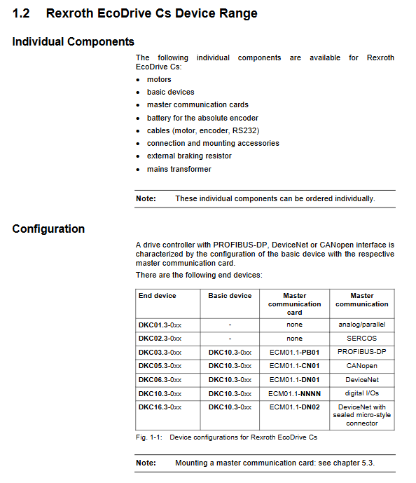
Controller classification and interface
Basic type (DKC10.3): No bus module, supports digital I/O control.
Bus type (DKC03.3/05.3/06.3): Supports PROFIBUS DP, CANopen, and DeviceNet respectively.
SERCOS type (DKC02.3): Fiber optic interface, switchable transmission power, maximum transmission 500m (glass fiber).
Analog/Parallel (DKC01.3): Supports ± 10V/4-20mA instructions, encoder simulation output.
Optional motor configuration
Encoder: incremental (relative position), absolute value (absolute position, battery backup required).
Axis type: optical axis (friction locking connection), key shaft (DIN 6885 standard).
Brake: 24VDC electric release type, brake torque 0.29~2.45 Nm, used for vertical axis anti fall.
List of Key Accessories
|Accessory type | Model example | Purpose|
|Motor cable | IKG0331 | Controller and motor power connection|
|Encoder cable | IKS0230 | Encoder signal transmission|
|Braking resistor | EBR01-0100-100R-V-D | Absorbs regenerative energy to avoid overvoltage|
|NTC Thermistor | SUP-E05-DCCS-SURGEP | Reduce Starting Impulse Current|
|Encoder adapter | SUP-E04-DKCCS-ENCODR | 1Vess encoder adapter|
Installation and wiring specifications
Controller installation requirements
Installation method: 35mm standard top cap guide rail, vertically installed (utilizing natural convection heat dissipation).
Space requirement: Reserve a heat dissipation gap of ≥ 40mm around the perimeter to avoid close placement with power electronic components.
Fixed torque: The installation screw torque is matched according to the model (such as using M4 screws for DKC02.3, with a torque of 3.1 Nm).
Core wiring specifications
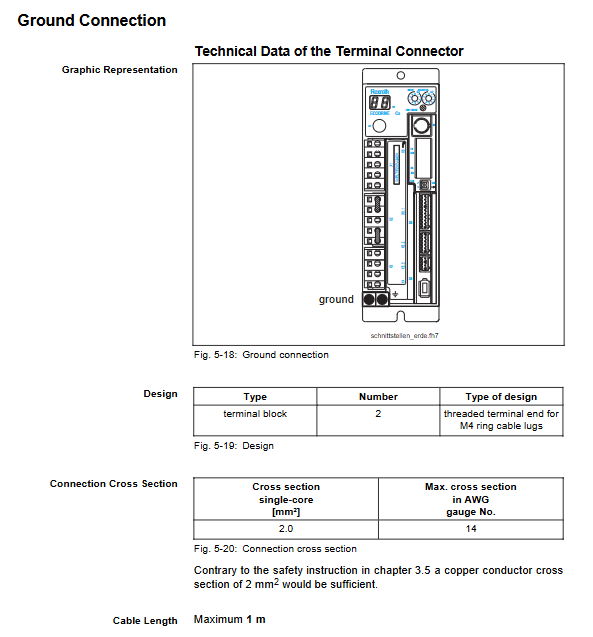
Power wiring: Single/three-phase power supply needs to match the voltage range, with a PE wire cross-section of ≥ 10 mm ² and a grounding resistance of ≤ 4 Ω.
Cable selection: The cross-sectional area of the power cable should be ≥ 0.75 mm ², and the encoder cable should be double shielded with a distance of ≥ 100mm from the power cable.
Bus wiring: A 121 Ω terminal resistor is required to be connected at both ends of the PROFIBUS DP bus, and the CANopen bus supports addresses 1-127.
EMC compliance requirements
Cable shielding: The shielding layer of power cables is grounded at one end, and the shielding layer of signal cables is grounded at both ends.
Filter configuration: A dedicated power filter (such as NFE01.1) needs to be installed to suppress electromagnetic interference.
Debugging and maintenance
Debugging process
Hardware connection: Use RS232 cable (IKB0041) to connect the PC and controller, and check the wiring before powering on.
Software configuration: Set motor parameters, control mode, and bus address through DriveTop software.
Trial operation: First test the speed/steering with no load, then verify the position accuracy with load, and confirm that the emergency stop function is effective.
routine maintenance
Motor maintenance: bearings are maintenance free (with a lifespan of 30000 hours), and the brake is activated for rust prevention every 48 hours.
Encoder maintenance: The battery life of the absolute value encoder is about 5 years, and it needs to be replaced with load to avoid position loss.
Controller maintenance: Check the wiring tightness annually, clean the dust on the heat sink, and avoid overload operation.
Fault handling
Diagnosis display: The H1 indicator light displays an error code, and the S1 button can reset non fatal errors.
Common faults: overvoltage (check brake resistance), overload (reduce load or prolong acceleration time), communication failure (check bus parameters).
Application scenarios and limitations
Applicable scenarios
Industrial equipment: handling and assembly systems, packaging and food machinery, printing machines, small machine tools.
Control requirements: Low power loads that require precise position/speed control, for single or multi axis synchronous applications.
Usage restrictions
Prohibited for use in personnel transportation equipment, medical equipment, and explosion-proof environments (non explosion-proof models).
If it exceeds the ambient temperature (0-40 ℃) or altitude (>1000m), it needs to be downgraded for use (2% for every 1 ℃ increase).
If the power supply voltage exceeds the range of 200~240V, an autotransformer (such as DST series) should be configured.
- YOKOGAWA
- Reliance
- ADVANCED
- SEW
- ProSoft
- WATLOW
- Kongsberg
- FANUC
- VSD
- DCS
- PLC
- man-machine
- Covid-19
- Energy and Gender
- Energy Access
- Renewable Integration
- Energy Subsidies
- Energy and Water
- Net zero emission
- Energy Security
- Critical Minerals
- A-B
- petroleum
- Mine scale
- Sewage treatment
- cement
- architecture
- Industrial information
- New energy
- Automobile market
- electricity
- Construction site
- HIMA
- ABB
- Rockwell
- Schneider Modicon
- Siemens
- xYCOM
- Yaskawa
- Woodward
- BOSCH Rexroth
- MOOG
- General Electric
- American NI
- Rolls-Royce
- CTI
- Honeywell
- EMERSON
- MAN
- GE
- TRICONEX
- Control Wave
- ALSTOM
- AMAT
- STUDER
- KONGSBERG
- MOTOROLA
- DANAHER MOTION
- Bentley
- Galil
- EATON
- MOLEX
- Triconex
- DEIF
- B&W
- ZYGO
- Aerotech
- DANFOSS
- KOLLMORGEN
- Beijer
- Endress+Hauser
- schneider
- Foxboro
- KB
- REXROTH
- YAMAHA
- Johnson
- Westinghouse
- WAGO
- TOSHIBA
- TEKTRONIX
- BENDER
- BMCM
- SMC
- HITACHI
- HIRSCHMANN
- XP POWER
- Baldor
- Meggitt
- SHINKAWA
- Other Brands
- UniOP
- KUKA
- IBA
- Beckhoff
-
Basler Electric DECS-250-CN1SN1N Automatic Voltage Regulator for Generator Excitation Control
-
ADLINK CPCI-6860A - 51-31310-OB10 industrial motherboard CompactPCI SBC
-
ADLINK AmITX-SL-G-H110 - 51-7A104-0A30 Mini-ITX Industrial Motherboard
-
ADLINK PXI-2005-003 - CPCI Industrial PC Data Acquisition Card Multi-Function DAQ
-
ADLINK DININ-814M - 51-14032-0A3D SCSI-100P cable connection Interface Terminal Board
-
ADLINK CPCI-3920NA/C2D15/M1G - 3U CompactPCI Intel Core 2 Duo Single Board Computer
-
ADLINK PCIE-8560 - 51-18014-0A20 Communication Card High Speed DAQ
-
ADLINK PCI-C154+ - Motion Control Card 4-axis Motion Controller Board
-
ADLINK PCI-RTV24 - image capture card Analog Video Frame Grabber
-
ADLINK NuPRO-842LV/P - 51-41360-0B30 Industrial Motherboard CPU Board
-
ADLINK cBP-3208/3208R - CPCI Board 3U 8-Slot CompactPCI Backplane
-
ADLINK PCI-8164 - 4-Axis Motion Controller PCI Card 51-12406-0A40
-
ADLINK PCIe-GIE64+ - 4-CH GigE Vision PoE+ Frame Grabber Video Capture Card
-
ADLINK CPCI-6860 / 6860A - CompactPCI Dual Xeon Single Board Computer
-
ADLINK IEC-915GV - REV 1.1 Industrial motherboard CPU Board
-
ADLINK ND-6520 - Technology RS-232 to RS-422RS-485 Converter NuDAM Module
-
ADLINK RTV-24 / PCI-MP4S - 51-12519-1C30 4-Channel Real Time Video Capture Board
-
ADLINK cPCI-6910 / cPCI-6910AM/M1G - cPCI-6910AM/DXL16/M1G/S80G(G)-3120 BOARD CompactPCI SBC
-
ADLINK NUPRO-A40H - Linghua 51-41807-1A30 Industrial Control Computer Motherboard
-
ADLINK USB-3488A - USB to GPIB INTERFACE USB-3488A(G) Controller Module
-
ADLINK PCI-8134A - motion control card 4-Axis Controller Card
-
ADLINK PCI-7432 - Board 32-Channel input / 32-output Isolated Digital I/O PCI Card
-
ADLINK PCI-8134A - 51-12421-0A10 motion controller card tested
-
ADLINK LPCIe-7230 - 32 CH Isolated Input/output Card 2 Interrupts Low Profile PCIe
-
ADLINK NuPRO-E340 - industrial computer motherboard 51-47807-0A30 PICMG 1.3 SHB
-
ADLINK PCI-7434 - High-speed Digital Acquisition Card 64-CH Isolated DO Card
-
ADLINK NuPRO-E330 - 51-41805-0A20 Indsutrial Board SHB Single Board Computer
-
ADLINK PCI-7248 - OPTO-22 48 CHANNEL DIO DIGITAL TTL/DTL I/O 51-12006-0A40 GP
-
ADLINK PCI-8134 - Motion control card 4-Axis Controller Card
-
ADLINK AMP-208C - Movimiento Control Tarjeta 51-12420-1A20 W/Expansión & Breakout
-
ADLINK PCI-8164 - 51-12406-0A40 PCB Board 4-Axis Motion Controller Card
-
ADLINK DIN-68Y-SGII / DIN-68M-J3A - Terminal Board Connector Interface Block
-
ADLINK PCIe-7432 - Technology 51-18402-0A10 PCIe Card With High Input Range
-
ADLINK PCI-8144 / PCI-8144N - Motion control card 4-Axis Stepper Controller Card
-
ADLINK HSL-HUB3/REPEATER - HIGH SPEED LINK EXTENSION MODULES Distributed Hub Module
-
ADLINK ND-6017 - Data Logging + Acquisition 8CH A/D input Mod NuDAM Module
-
ADLINK LPCIe-7250 - data acquisition card Low Profile 8-CH Relay Output Card
-
ADLINK PCI-7432 - I/O card 64-CH Isolated Digital Input Output PCI Card
-
ADLINK IMB-M43H - industrial control computer motherboard Q87 Chip Micro-ATX
-
ADLINK MP-C154 - Motion control Card 4-Axis Motion Controller Board
-
ADLINK PCI-RTV24 - image capture card Video Frame Grabber Card
-
ADLINK PCI-7250 - 8-CH Relay Output & 8-CH Isolated DI Card
-
ADLINK PCI-6308V - 8-CH 12-Bit Isolated Analog Output PCI Card PCB-I-E-1148=6EX2
-
ADLINK PCI-7248 - capture card 48-CH Opto-22 Compatible DIO Card
-
ADLINK HSL-AI16A02-M-VV - Analog Input Output Distributed Module
-
ADLINK NuPRO-A301 - Rev:1.4 NUPRO-A301 PICMG Full-Size Single Board Computer
-
ADLINK PCI-6208V-GL - 8-CH Voltage Analog Output PCI Card
-
ADLINK PCI-8134A - 51-12421-0A10 4-Axis Motion Controller Card
-
ADLINK MNET-S23 - TECHNOLOGY MNET S23 - SERVO DRIVER CONTROL MODULE
-
ADLINK M-342 - ATX I3 I5 I7 Q67 Industrial Motherboard
-
ADLINK NUPRO-780 - Industrial Motherboard CPU Board PICMG SBC
-
ADLINK MP-C154 / MP-C152 - 4-Axis Motion Control Card Pulse-Train Controller
-
ADLINK NuPRO-935A/LV10B0 - Motherboard 51-41802-0A10 GP w/RAM Industrial Control Board
-
ADLINK MP-C154 - Motion control card 4-Axis Motion Controller Mainboard
-
ADLINK PCI-7250 - PCI Acquisition Card 8-CH Relay Output Isolated DI Card
-
ADLINK ACL-7124 - Technology Inc.24 DIO Card Digital Input Output Card
-
ADLINK PCI-8554 A2 - Timer/Counter Data Acquisition Card
-
ADLINK DIN-825-GP4 - Terminal Block Interface Board Breakout Module
-
ADLINK NuPR0-761 - REV:1.1 Industrial motherboard Full-Size PICMG SBC
-
ADLINK MXE-1401/M8G (G) - Matrix Fanless Embedded Computer Industrial PC
-
ADLINK HSL-DI16DO16-UD-NN - Digital 16 Channel I/O Mod Distributed I/O Module
-
ADLINK ND6520 - NUDAM INTELLIGENT DA&C MODULE RS232-RS-422/RS485 CONVERTOR
-
ADLINK NUPRO-761 - REV:1.1 Industrial Motherboard CPU Board
-
ADLINK AMP-208C - Motion Control Card 51-12420-1A20 DSP-based 8-axis
-
ADLINK NuPRO-A301REV 1.4 - with packaging industrial computer motherboard PICMG SBC
-
ADLINK PCM-9112+ - 51-12300-0A2 industrial motherboard Multi-Function DAQ PC/104 Module
-
ADLINK PCM-7250+ - 8-CH Relay Outputs & 8-CH Isolated DI Module PC/104
-
ADLINK PCI-RTV24 - Image capture card Analog Video Frame Grabber
-
ADLINK PCI-8134 - Motion Controller PCI Card 4-Axis Controller Board
-
ADLINK PCI-7432 - Isolated Digital I/O PCI Card
-
ADLINK PCI-8554 A2 - acquisition card Timer/Counter Card
-
ADLINK PCI-8132 - Rev.A2 2-Axis Servo & Stepper Motion Controller Card
-
ADLINK PCI-8132 - Data Acquisition card 2-Axis Motion Controller Card
-
ADLINK EBP-13E4 - 51-46703-0A30 Industrial Backplane Board Passive Backplane
-
ADLINK PCI-800L - Electronic Card Interface Controller Card
-
ADLINK PCIe-GIE72 - 51-18531-0A10 PCB Board GigE Vision Frame Grabber
-
ADLINK DAQ-2010(G)-OOBO - Simultaneous-Sampling Multi-Function DAQ Card
-
ADLINK PCI-9112 - REV.B1 Multifunction DAQ Card Data Acquisition Card
-
ADLINK PCI-7230 - 51-12003-DA60 32-CH Isolated Digital I/O Card
-
ADLINK PCI-7432 - Data Acquisition Card Isolated Digital I/O PCI Card
-
ADLINK ETX-AT-N270-18/LXE - 51-71111-0A20 ETX CPU Module Motherboard
-
ADLINK HSL-DI32-UD-N - DIGITAL INPUT 32 POINTS MODULE Distributed I/O
-
ADLINK AMP-204C - Motion Control card DSP-Based 4-Axis Advanced Controller
-
ADLINK MNET-4XMOG-0050 - Four-axis Motion Controller Distributed Motion Module
-
ADLINK AMP-204C - Motion control card DSP-Based 4-Axis Pulse-Train Controller
-
ADLINK PCI-7442 - Switch card 64-Channel Datalogging & Acquisition Card
-
ADLINK M-302 - Industrial control motherboard ATX PC Board
-
ADLINK NUPRO-852 / NUPRO-852LV - Industrial motherboard Single Board Computer
-
ADLINK PCI-8134 - REV.B1. 4-Axis Motion Controller Card
-
ADLINK PCI-GIE62 + - 51-18502-0A20 2-CH GigE Vision Frame Grabber PoE Card
-
ADLINK PCI-MPG24 - 51-12523-0B20 MPEG4 Card Video Compression Hardware
-
ADLINK HSL-TB32-M-DIN - 32-CH I/O TERMINAL W/ HSL-AI16AO2-M-VV MODULE
-
ADLINK PCI-M114-GL - PCB Ver 2.1 Motion Controller Axis Card
-
ADLINK IMB-M40H - SYM76996H61 motherboard Industrial Computer Mainboard
-
ADLINK NUPRO-A40H - 51-41807-1A20 industrial control motherboard H61 Chip
-
ADLINK PCI-M114-GL - Axis Card Data Acquisition Card PCB VER2.2 Motion Controller
-
ADLINK PCI-8134 - Motion Controller PCI Card 4-Axis Controller Board
-
ADLINK PCI-8102 - Motion control card 2-Axis Servo & Stepper Controller
-
ADLINK NuPRO-841REV:3.0 - motherboard Industrial Control PC Board
-
ADLINK HSL-TB32-U-DIN REV A1 - Breakout Terminal Board Field I/O Module
-
ADLINK AMP-204C - Motion Control card DSP-Based 4-Axis Pulse-Train Controller
-
ADLINK NUPRO-A40H - 51-41807-1A20 industrial control motherboard H61 PC Board
-
ADLINK PCI-6308A / PCI-6308V - 51-12202-0A50 Isolated Analog Output Card
-
ADLINK AMP-204C - DSP-Based 4-Axis Advanced Pulse-Train Motion Controller
-
ADLINK PCI-7434 - Technology 64-Channel Isolated Digital I/O PCI Cards
-
ADLINK CPCI-6840 / CPCI-6840V / PM16/M1G-12G0 - CompactPCI Single Board Computer CPU Module
-
ADLINK PCIE-GIE74 - Motherboard Video Capture Card 51-18531-0A10 Frame Grabber
-
ADLINK NuPRO-E330 - industrial computer equipment motherboard Control Mainboard
-
ADLINK AMP-208C / 51-12420-1A20 - Motion Control Card W/ Expansion & Breakout Board
-
ADLINK HPCI-14S12U - industrial computer baseboard Passive Backplane 14 Slots
-
ADLINK PCI-8164 - 4-Axis Motion Controller PCI Card W/ 1x Cable, 1x Breakout Box
-
ADLINK PCIe-RTV24 - 51-18016-0A20 Image Acquisition Video Capture Card
-
ADLINK M-342 - 5 PCI ATX Motherboard Industrial PC Mainboard
-
ADLINK PCI-FIW64 - 4/2 Channel IEEE1394B Image Capture Card FireWire Frame Grabber
-
ADLINK PCI-7432 - digital IO card 64-CH Isolated Digital Input Output Card
-
ADLINK 51-12001-0C20 - Circuit Board PCI-7200 Data Acquisition Controller Card
-
ADLINK PXI-3920 - PXI 3U cPCI Industrial Controller Embedded System CPU Board
-
ADLINK NuPRO-841REV:2.0 - motherboard Industrial Control PC Board
-
ADLINK NuPro-E330 - 51-41805-0A20 PCB Industrial Control Computer Motherboard
-
ADLINK PCI-RTV24 - Image capture card Analog Video Frame Grabber
-
ADLINK PCI-7442 - Switch card 64-Channel Datalogging & Acquisition Card
-
ADLINK HPX-13S4 - device baseboard Passive Backplane Riser Card
-
ADLINK PCI-9112 REV A.1 - Multi Function DA&C Board Data Acquisition Card
-
ADLINK PCI-7248 - 51-12006-0A40 Card Control 48-CH Digital I/O Module
-
ADLINK CPCI-6860 / 6860A - motherboard CompactPCI Dual Xeon Single Board Computer
-
ADLINK DPAC-3020-11(G) - Embedded PC Automation Controller Machine Control Board
-
ADLINK NuPRO-841 REV:1.0 - industrial control motherboard CPU Board
-
ADLINK MNET-4XMOG-0050 - Four-axis Motion Controller MNET Motion Control Card

K-JIANG

Add: Jimei North Road, Jimei District, Xiamen, Fujian, China
Tell:+86-15305925923