
K-WANG


REXRTOH SE 200 Electric Tool Controller and Supporting LTH Power Unit
REXRTOH SE 200 Electric Tool Controller and Supporting LTH Power Unit
Basic Information
Core product portfolio
SE 200 Controller: The core control unit of the electric tool system, responsible for program selection, job control, and status feedback.
LTH power unit: a frequency converter that provides a variable power/frequency rotating magnetic field for EC motors, available in two specifications: 230V (order number 0 608 750 056) and 110V (order number 0 608 750 064).
Document type and purpose: Official technical manual, covering safe operation, installation and wiring, functional settings, fault handling, etc., suitable for electric tightening/loosening operation systems in industrial assembly scenarios.
Adapt devices and accessories
Suitable motors: EC 37, EC 48 type EC motors (such as ECH12-MG, ECH37-MG, etc., please refer to the appendix for order numbers).
Core accessories: current control board ST1, programming module PM-1, dedicated connection cable (straight 1.6-10m/spiral 6.3-10m).
Core Technical Parameters
Parameter Category Specific Parameters LTH 230V LTH 110V Remarks
Power supply parameters rated voltage 220-240V AC 100-110V AC 50/60Hz ± 10%
Maximum input current 10A 20A-
Power consumption 400VA 400VA-
Output parameters Output voltage range 0-230V 0-230V-
Rated output current 2A 2A-
Maximum output current 12A 12A-
Output frequency range 0-500Hz 0-500Hz, suitable for motor speed regulation
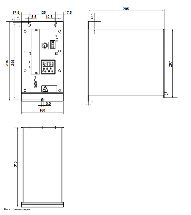
Physical dimensions (length x width x height) 310 × 160 × 310mm 310 × 160 × 310mm-
Weight 13.4kg 13.4kg including installation accessories
Environmental parameters Operating temperature 0-50 ℃ 0-50 ℃-
Storage temperature -20-70 ℃ -20-70 ℃-
Relative humidity 20-90% (no condensation) 20-90% (no condensation)-
Protection and Electromagnetic Compatibility Protection Level IP 42 IP 42 Solid Foreign Object Protection+Splash Protection
EMC level IEC 801 level 4 IEC 801 level 4 Anti electromagnetic interference
Data storage battery specifications: 2 1/2 AA 3.6V lithium batteries, 2 1/2 AA 3.6V lithium batteries, data storage for 8 years
Key points of safety regulations
Electrical safety
After power failure, it is necessary to confirm that there is no voltage before operation to avoid the risk of high voltage electric shock.
It is strictly prohibited to connect the motor to the PE line. Electrical isolation should be achieved by relying on the isolation transformer of the LTH power unit (in accordance with VDE 0551 standard).
The fuse (6.3A slow melting type) is only allowed to be replaced by professionals and unauthorized modification of the circuit is prohibited.
Operational Security
Only trained and qualified personnel are allowed to operate, and they must be familiar with safety regulations and equipment functions.
In environments with severe dust or high humidity, the LTH unit needs to be installed in a control cabinet with an IP 54 protection level.
It is prohibited to connect non specialized equipment (such as coffee makers, toasters, etc.) to IEC sockets.
Equipment Protection
During installation, a ventilation gap of ≥ 40mm should be reserved to avoid overheating caused by poor heat dissipation.
Transportation and storage should avoid severe vibration, condensation, and dust pollution.
Installation and wiring specifications
(1) Installation requirements
Installation method: Hanging installation is carried out through the back hanging ears, without the need to be in close proximity to power tools.
Cable limitation: The maximum length of the cable between the LTH power unit and the motor should not exceed 50m, and original factory specific cables must be used.
Environmental adaptation: Install directly in regular environments, but in harsh environments, an IP 54 control cabinet is required.
(2) Core Interface Definition (Summary of Key Interfaces)
Interface Identification Type Pin Count Core Function Key Pin Description
X1 (Netz) IEC socket 3 (L/N/PE) power input L=phase wire, N=neutral wire, PE=ground wire
X3 (Handschauber) circular plug 19+PE motor connection U/V/W=motor phase line, TMA=motor temperature sensor
X2 (Sensorik SE200) SUB-D socket 15 sensor signal CLK/DATA=RS422 serial signal, 24VSE=control power supply
X7 (Betriebsmittelsteuerung) SUB-D socket 37 material control SSR=tighten start, SLL=loosen start, IO/NIO=job success/failure signal
X8 (Kommandoleitung) SUB-D plug 25 command line ST1-ST3=speed gear, FG=release signal, IM1/IM2=torque measurement
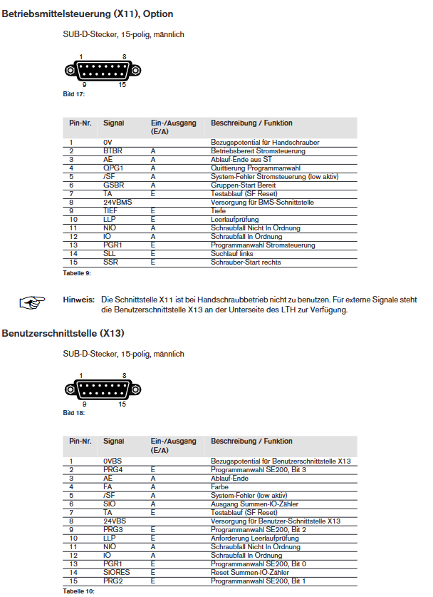
X13 (Benutzerschnittstelle) SUB-D plug 15 user interface SIO=IO count output, SF=system fault, TA=test reset
(3) Wiring process
Connect the interface cable and secure it with screws to ensure reliable contact.
Insert the Amphenol plug into the motor and tighten the locking ring.
Connect the power cable (IEC plug) and secure it with a wire clamp.
By turning on the bottom power switch, the device automatically performs hardware self-test.
Operation and Function Description
(1) Core components of panel operation
Motor selection switch: Switch the EC 37/EC 48 motor type, and the corresponding LED indicator light will light up to confirm.
Program selection mode:
Internal mode: Select the 0-15 program through the panel buttons (even=tighten P0, odd=tighten P1, 15=loosen SLL).
External mode: Select the program using hexadecimal code through the X13 interface, and the "ExternalN" LED will light up.
IO Count Statistician:
Function: Record the number of qualified assignments (0-999999), supporting cumulative/decreasing modes.
Operation: Reset with the red SET button, set preset values with 6 buttons, and display "Lo bat" for low battery.
Fault handling: Reset the fault by pressing the "RESET" button. If the power module fails, the device needs to be restarted.
(2) Core functional parameters
Parameter Name Optional Setting Default Value Function Description
Count mode: Add/SubAdd: Count from 0 to the preset value; Decrease: Count from preset value to 0
Loop mode: On/Off Off On=Delay reset loop after reaching the preset value; Off=continuous counting without looping
Relay output type when NO (normally open)/NC (normally closed) NO count meets the standard
Delay 100/200/300/400/500ms - SIO signal duration when Loop=On
DP (decimal point) with no/1/2 decimal places and no count display
(3) Homework process
Select motor type (EC 37/EC 48) and program mode (internal/external).
Set the preset value and working parameters of the IO counter (accumulate/decrease, loop, etc.).
Trigger the operation (tightening/loosening) through the X7 interface or motor start button.
After the homework is completed, the IO/NIO signal feedback indicates success or failure, and the counter is automatically updated.
When there is a malfunction, the corresponding LED lights up, and after resetting, the operation can be restarted.
Fault diagnosis
(1) Common faults and LED indications
LED identification color fault type handling method
USP red middle circuit overvoltage check power supply voltage, reset device
If the NTF red power module fails, restart the device. If it is ineffective, return it to the factory for repair
TF/TFVM red temperature fault (unit/motor), restart after cooling, check heat dissipation and temperature sensor
FI red current fault (short circuit): Check the motor cable and eliminate the short circuit point
BL red motor stalling check load, eliminate mechanical jamming
Accessory ordering information (core accessories)
Accessory category Product name Order number Remarks
Power Unit LTH 230V 0 608 750 056-
LTH 110V 0 608 750 064 -
Controller SE 200 Electric Tool Control 0 608 830 123-
Motor ECH37-MG 0 608 841 009 EC 37 type
ECH48-MG 0 608 841 010 EC 48 type
Cable straight cable (4.0m) 0 608 750 067 motor connection
Spiral cable (6.3m) 0 608 750 070 motor connection
Control module current control board ST1 0 608 750 054 optional accessories
Programming module PM-1 0 608 750 055 optional accessories
- YOKOGAWA
- Reliance
- ADVANCED
- SEW
- ProSoft
- WATLOW
- Kongsberg
- FANUC
- VSD
- DCS
- PLC
- man-machine
- Covid-19
- Energy and Gender
- Energy Access
- Renewable Integration
- Energy Subsidies
- Energy and Water
- Net zero emission
- Energy Security
- Critical Minerals
- A-B
- petroleum
- Mine scale
- Sewage treatment
- cement
- architecture
- Industrial information
- New energy
- Automobile market
- electricity
- Construction site
- HIMA
- ABB
- Rockwell
- Schneider Modicon
- Siemens
- xYCOM
- Yaskawa
- Woodward
- BOSCH Rexroth
- MOOG
- General Electric
- American NI
- Rolls-Royce
- CTI
- Honeywell
- EMERSON
- MAN
- GE
- TRICONEX
- Control Wave
- ALSTOM
- AMAT
- STUDER
- KONGSBERG
- MOTOROLA
- DANAHER MOTION
- Bentley
- Galil
- EATON
- MOLEX
- Triconex
- DEIF
- B&W
- ZYGO
- Aerotech
- DANFOSS
- KOLLMORGEN
- Beijer
- Endress+Hauser
- schneider
- Foxboro
- KB
- REXROTH
- YAMAHA
- Johnson
- Westinghouse
- WAGO
- TOSHIBA
- TEKTRONIX
- BENDER
- BMCM
- SMC
- HITACHI
- HIRSCHMANN
- XP POWER
- Baldor
- Meggitt
- SHINKAWA
- Other Brands
- UniOP
- KUKA
- IBA
- Beckhoff
-
Basler Electric DECS-250-CN1SN1N Automatic Voltage Regulator for Generator Excitation Control
-
ADLINK CPCI-6860A - 51-31310-OB10 industrial motherboard CompactPCI SBC
-
ADLINK AmITX-SL-G-H110 - 51-7A104-0A30 Mini-ITX Industrial Motherboard
-
ADLINK PXI-2005-003 - CPCI Industrial PC Data Acquisition Card Multi-Function DAQ
-
ADLINK DININ-814M - 51-14032-0A3D SCSI-100P cable connection Interface Terminal Board
-
ADLINK CPCI-3920NA/C2D15/M1G - 3U CompactPCI Intel Core 2 Duo Single Board Computer
-
ADLINK PCIE-8560 - 51-18014-0A20 Communication Card High Speed DAQ
-
ADLINK PCI-C154+ - Motion Control Card 4-axis Motion Controller Board
-
ADLINK PCI-RTV24 - image capture card Analog Video Frame Grabber
-
ADLINK NuPRO-842LV/P - 51-41360-0B30 Industrial Motherboard CPU Board
-
ADLINK cBP-3208/3208R - CPCI Board 3U 8-Slot CompactPCI Backplane
-
ADLINK PCI-8164 - 4-Axis Motion Controller PCI Card 51-12406-0A40
-
ADLINK PCIe-GIE64+ - 4-CH GigE Vision PoE+ Frame Grabber Video Capture Card
-
ADLINK CPCI-6860 / 6860A - CompactPCI Dual Xeon Single Board Computer
-
ADLINK IEC-915GV - REV 1.1 Industrial motherboard CPU Board
-
ADLINK ND-6520 - Technology RS-232 to RS-422RS-485 Converter NuDAM Module
-
ADLINK RTV-24 / PCI-MP4S - 51-12519-1C30 4-Channel Real Time Video Capture Board
-
ADLINK cPCI-6910 / cPCI-6910AM/M1G - cPCI-6910AM/DXL16/M1G/S80G(G)-3120 BOARD CompactPCI SBC
-
ADLINK NUPRO-A40H - Linghua 51-41807-1A30 Industrial Control Computer Motherboard
-
ADLINK USB-3488A - USB to GPIB INTERFACE USB-3488A(G) Controller Module
-
ADLINK PCI-8134A - motion control card 4-Axis Controller Card
-
ADLINK PCI-7432 - Board 32-Channel input / 32-output Isolated Digital I/O PCI Card
-
ADLINK PCI-8134A - 51-12421-0A10 motion controller card tested
-
ADLINK LPCIe-7230 - 32 CH Isolated Input/output Card 2 Interrupts Low Profile PCIe
-
ADLINK NuPRO-E340 - industrial computer motherboard 51-47807-0A30 PICMG 1.3 SHB
-
ADLINK PCI-7434 - High-speed Digital Acquisition Card 64-CH Isolated DO Card
-
ADLINK NuPRO-E330 - 51-41805-0A20 Indsutrial Board SHB Single Board Computer
-
ADLINK PCI-7248 - OPTO-22 48 CHANNEL DIO DIGITAL TTL/DTL I/O 51-12006-0A40 GP
-
ADLINK PCI-8134 - Motion control card 4-Axis Controller Card
-
ADLINK AMP-208C - Movimiento Control Tarjeta 51-12420-1A20 W/Expansión & Breakout
-
ADLINK PCI-8164 - 51-12406-0A40 PCB Board 4-Axis Motion Controller Card
-
ADLINK DIN-68Y-SGII / DIN-68M-J3A - Terminal Board Connector Interface Block
-
ADLINK PCIe-7432 - Technology 51-18402-0A10 PCIe Card With High Input Range
-
ADLINK PCI-8144 / PCI-8144N - Motion control card 4-Axis Stepper Controller Card
-
ADLINK HSL-HUB3/REPEATER - HIGH SPEED LINK EXTENSION MODULES Distributed Hub Module
-
ADLINK ND-6017 - Data Logging + Acquisition 8CH A/D input Mod NuDAM Module
-
ADLINK LPCIe-7250 - data acquisition card Low Profile 8-CH Relay Output Card
-
ADLINK PCI-7432 - I/O card 64-CH Isolated Digital Input Output PCI Card
-
ADLINK IMB-M43H - industrial control computer motherboard Q87 Chip Micro-ATX
-
ADLINK MP-C154 - Motion control Card 4-Axis Motion Controller Board
-
ADLINK PCI-RTV24 - image capture card Video Frame Grabber Card
-
ADLINK PCI-7250 - 8-CH Relay Output & 8-CH Isolated DI Card
-
ADLINK PCI-6308V - 8-CH 12-Bit Isolated Analog Output PCI Card PCB-I-E-1148=6EX2
-
ADLINK PCI-7248 - capture card 48-CH Opto-22 Compatible DIO Card
-
ADLINK HSL-AI16A02-M-VV - Analog Input Output Distributed Module
-
ADLINK NuPRO-A301 - Rev:1.4 NUPRO-A301 PICMG Full-Size Single Board Computer
-
ADLINK PCI-6208V-GL - 8-CH Voltage Analog Output PCI Card
-
ADLINK PCI-8134A - 51-12421-0A10 4-Axis Motion Controller Card
-
ADLINK MNET-S23 - TECHNOLOGY MNET S23 - SERVO DRIVER CONTROL MODULE
-
ADLINK M-342 - ATX I3 I5 I7 Q67 Industrial Motherboard
-
ADLINK NUPRO-780 - Industrial Motherboard CPU Board PICMG SBC
-
ADLINK MP-C154 / MP-C152 - 4-Axis Motion Control Card Pulse-Train Controller
-
ADLINK NuPRO-935A/LV10B0 - Motherboard 51-41802-0A10 GP w/RAM Industrial Control Board
-
ADLINK MP-C154 - Motion control card 4-Axis Motion Controller Mainboard
-
ADLINK PCI-7250 - PCI Acquisition Card 8-CH Relay Output Isolated DI Card
-
ADLINK ACL-7124 - Technology Inc.24 DIO Card Digital Input Output Card
-
ADLINK PCI-8554 A2 - Timer/Counter Data Acquisition Card
-
ADLINK DIN-825-GP4 - Terminal Block Interface Board Breakout Module
-
ADLINK NuPR0-761 - REV:1.1 Industrial motherboard Full-Size PICMG SBC
-
ADLINK MXE-1401/M8G (G) - Matrix Fanless Embedded Computer Industrial PC
-
ADLINK HSL-DI16DO16-UD-NN - Digital 16 Channel I/O Mod Distributed I/O Module
-
ADLINK ND6520 - NUDAM INTELLIGENT DA&C MODULE RS232-RS-422/RS485 CONVERTOR
-
ADLINK NUPRO-761 - REV:1.1 Industrial Motherboard CPU Board
-
ADLINK AMP-208C - Motion Control Card 51-12420-1A20 DSP-based 8-axis
-
ADLINK NuPRO-A301REV 1.4 - with packaging industrial computer motherboard PICMG SBC
-
ADLINK PCM-9112+ - 51-12300-0A2 industrial motherboard Multi-Function DAQ PC/104 Module
-
ADLINK PCM-7250+ - 8-CH Relay Outputs & 8-CH Isolated DI Module PC/104
-
ADLINK PCI-RTV24 - Image capture card Analog Video Frame Grabber
-
ADLINK PCI-8134 - Motion Controller PCI Card 4-Axis Controller Board
-
ADLINK PCI-7432 - Isolated Digital I/O PCI Card
-
ADLINK PCI-8554 A2 - acquisition card Timer/Counter Card
-
ADLINK PCI-8132 - Rev.A2 2-Axis Servo & Stepper Motion Controller Card
-
ADLINK PCI-8132 - Data Acquisition card 2-Axis Motion Controller Card
-
ADLINK EBP-13E4 - 51-46703-0A30 Industrial Backplane Board Passive Backplane
-
ADLINK PCI-800L - Electronic Card Interface Controller Card
-
ADLINK PCIe-GIE72 - 51-18531-0A10 PCB Board GigE Vision Frame Grabber
-
ADLINK DAQ-2010(G)-OOBO - Simultaneous-Sampling Multi-Function DAQ Card
-
ADLINK PCI-9112 - REV.B1 Multifunction DAQ Card Data Acquisition Card
-
ADLINK PCI-7230 - 51-12003-DA60 32-CH Isolated Digital I/O Card
-
ADLINK PCI-7432 - Data Acquisition Card Isolated Digital I/O PCI Card
-
ADLINK ETX-AT-N270-18/LXE - 51-71111-0A20 ETX CPU Module Motherboard
-
ADLINK HSL-DI32-UD-N - DIGITAL INPUT 32 POINTS MODULE Distributed I/O
-
ADLINK AMP-204C - Motion Control card DSP-Based 4-Axis Advanced Controller
-
ADLINK MNET-4XMOG-0050 - Four-axis Motion Controller Distributed Motion Module
-
ADLINK AMP-204C - Motion control card DSP-Based 4-Axis Pulse-Train Controller
-
ADLINK PCI-7442 - Switch card 64-Channel Datalogging & Acquisition Card
-
ADLINK M-302 - Industrial control motherboard ATX PC Board
-
ADLINK NUPRO-852 / NUPRO-852LV - Industrial motherboard Single Board Computer
-
ADLINK PCI-8134 - REV.B1. 4-Axis Motion Controller Card
-
ADLINK PCI-GIE62 + - 51-18502-0A20 2-CH GigE Vision Frame Grabber PoE Card
-
ADLINK PCI-MPG24 - 51-12523-0B20 MPEG4 Card Video Compression Hardware
-
ADLINK HSL-TB32-M-DIN - 32-CH I/O TERMINAL W/ HSL-AI16AO2-M-VV MODULE
-
ADLINK PCI-M114-GL - PCB Ver 2.1 Motion Controller Axis Card
-
ADLINK IMB-M40H - SYM76996H61 motherboard Industrial Computer Mainboard
-
ADLINK NUPRO-A40H - 51-41807-1A20 industrial control motherboard H61 Chip
-
ADLINK PCI-M114-GL - Axis Card Data Acquisition Card PCB VER2.2 Motion Controller
-
ADLINK PCI-8134 - Motion Controller PCI Card 4-Axis Controller Board
-
ADLINK PCI-8102 - Motion control card 2-Axis Servo & Stepper Controller
-
ADLINK NuPRO-841REV:3.0 - motherboard Industrial Control PC Board
-
ADLINK HSL-TB32-U-DIN REV A1 - Breakout Terminal Board Field I/O Module
-
ADLINK AMP-204C - Motion Control card DSP-Based 4-Axis Pulse-Train Controller
-
ADLINK NUPRO-A40H - 51-41807-1A20 industrial control motherboard H61 PC Board
-
ADLINK PCI-6308A / PCI-6308V - 51-12202-0A50 Isolated Analog Output Card
-
ADLINK AMP-204C - DSP-Based 4-Axis Advanced Pulse-Train Motion Controller
-
ADLINK PCI-7434 - Technology 64-Channel Isolated Digital I/O PCI Cards
-
ADLINK CPCI-6840 / CPCI-6840V / PM16/M1G-12G0 - CompactPCI Single Board Computer CPU Module
-
ADLINK PCIE-GIE74 - Motherboard Video Capture Card 51-18531-0A10 Frame Grabber
-
ADLINK NuPRO-E330 - industrial computer equipment motherboard Control Mainboard
-
ADLINK AMP-208C / 51-12420-1A20 - Motion Control Card W/ Expansion & Breakout Board
-
ADLINK HPCI-14S12U - industrial computer baseboard Passive Backplane 14 Slots
-
ADLINK PCI-8164 - 4-Axis Motion Controller PCI Card W/ 1x Cable, 1x Breakout Box
-
ADLINK PCIe-RTV24 - 51-18016-0A20 Image Acquisition Video Capture Card
-
ADLINK M-342 - 5 PCI ATX Motherboard Industrial PC Mainboard
-
ADLINK PCI-FIW64 - 4/2 Channel IEEE1394B Image Capture Card FireWire Frame Grabber
-
ADLINK PCI-7432 - digital IO card 64-CH Isolated Digital Input Output Card
-
ADLINK 51-12001-0C20 - Circuit Board PCI-7200 Data Acquisition Controller Card
-
ADLINK PXI-3920 - PXI 3U cPCI Industrial Controller Embedded System CPU Board
-
ADLINK NuPRO-841REV:2.0 - motherboard Industrial Control PC Board
-
ADLINK NuPro-E330 - 51-41805-0A20 PCB Industrial Control Computer Motherboard
-
ADLINK PCI-RTV24 - Image capture card Analog Video Frame Grabber
-
ADLINK PCI-7442 - Switch card 64-Channel Datalogging & Acquisition Card
-
ADLINK HPX-13S4 - device baseboard Passive Backplane Riser Card
-
ADLINK PCI-9112 REV A.1 - Multi Function DA&C Board Data Acquisition Card
-
ADLINK PCI-7248 - 51-12006-0A40 Card Control 48-CH Digital I/O Module
-
ADLINK CPCI-6860 / 6860A - motherboard CompactPCI Dual Xeon Single Board Computer
-
ADLINK DPAC-3020-11(G) - Embedded PC Automation Controller Machine Control Board
-
ADLINK NuPRO-841 REV:1.0 - industrial control motherboard CPU Board
-
ADLINK MNET-4XMOG-0050 - Four-axis Motion Controller MNET Motion Control Card

K-JIANG

Add: Jimei North Road, Jimei District, Xiamen, Fujian, China
Tell:+86-15305925923