
K-WANG


DEIF RMV-111D undervoltage and overvoltage relay
DEIF RMV-111D undervoltage and overvoltage relay
Product core positioning
RMV-111D is a combined undervoltage and overvoltage relay in the "uni line" series of DEIF company, mainly used for the protection and control of generators. Through three-phase voltage detection, it achieves dual protection of undervoltage (U<) and overvoltage (U>), and is equipped with functions such as timed tripping and fault status LED indication to ensure voltage stability of the power generation system.
Product identification and key information (label content)
The relay comes with a label that indicates the core parameters, which is a key basis for contacting the manufacturer and confirming the configuration, including:
Basic model: RMV-112D (e.g. example label: TYPE RMV-112D 121120).
Measurement and power supply parameters: measurement voltage (such as 230V/400V), voltage module specifications (such as MODULE 230V), auxiliary power supply voltage (such as 24VDC), wiring method (star "STAR" or triangle "DELTA", example label includes "COUPLING DELTA").
Special configurations: delay time, special calibration values, etc. (pre-set by DEIF).
Compliance and labeling: CE certification, installation category (such as CAT III), maximum voltage to ground, dealer number (to be filled in by the dealer).
Relay characteristics: Label the action mode of the relay (such as "RELAY NORM. ENERGY" normally energized type, "LATCH" latch function), the latch circuit needs to disconnect the power supply voltage and reset, even if the input returns to normal, the contacts will still remain in the alarm position.
Note: The relay is equipped with a 200ms power on/off protection circuit: the normally energized contact (NE) does not operate within 200ms after power on to ensure stable function; Monitor the voltage within 200ms after power failure to avoid misjudgment.
Installation instructions
1. Installation method and specifications
Installation type: Supports panel installation, can be fixed on a 35mm DIN rail, or directly installed with 2 4mm screws.
Weight: Approximately 0.650kg.
Spacing requirement: It can be installed in close proximity to other "uni line" series units, but the distance between the relay and other devices/relays must be ≥ 50mm.
Rail placement: If multiple relays are installed on the same DIN rail, the rail must be placed horizontally.
2. Wiring precautions
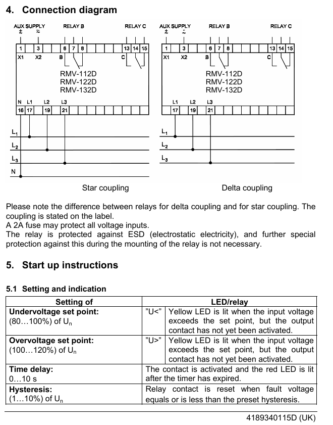
Wiring differences: It is necessary to distinguish between star (STAR) and delta (DELTA) wiring methods. The specific wiring method should be marked on the product label, and refer to the "Connection diagram" for operation.
Voltage protection: All voltage input terminals can be connected in series with 2A fuses to prevent overcurrent damage.
Static protection: The relay comes with ESD (electrostatic discharge) protection, and no additional anti-static measures are required during installation.
Startup and parameter settings
1. Core parameter setting and indication
Set key parameters through the front knob of the relay and provide feedback on the status with LED lights. The specific correspondence is as follows:
Range of parameter settings: LED/relay action feedback
When the input voltage is lower than the set value (U<) and the rated voltage (U ₙ) is 80%~100%, the corresponding yellow LED will light up (the contact is not activated at this time); After the delay is over, the contact will activate and the red LED will light up
When the input voltage is higher than the set value, the yellow LED of "U>" will light up (at this time, the contact is not activated) when the overvoltage setting value (U>) is 100%~120% of the rated voltage (U ₙ); After the delay is over, the contact will activate and the red LED will light up
After a delay of 0-10s, the relay contacts will activate and the red LED will light up
Hysteresis: 1%~10% of the rated voltage (U ₙ) of the hysteresis value is shared by undervoltage/overvoltage. When the fault voltage drops/rises to within the hysteresis value, the relay contacts reset
2. Set examples (to help understand)
Assuming rated voltage range (U ₙ): 95~105V
Undervoltage setting value: 90% of U ₙ (i.e. 90V)
Overvoltage setting value: 110% of U ₙ (i.e. 110V)
Return difference: 5% of U ₙ (i.e. 5V)
The relay is activated when the voltage is ≤ 90V (under voltage) or ≥ 110V (over voltage); When the voltage returns to the range of 95-105V, the contacts reset.
3. Accuracy Description
Front knob setting accuracy: usually ± 10% of the scale, corresponding to ± 2% of the rated voltage (U ₙ).
Higher precision requirement: It is necessary to adjust the equipment connected to the relay (such as the generator) until the target set value is reached.
Technical specifications
Category specific parameters
Frequency range 40~45~65~70Hz
Continuous maximum input voltage: 1.2 × U ₙ; 10s short-term maximum input: 2 × U ₙ
Load requirement of 2k Ω/V
Relay contact: 1 transfer switch for each relay; Rated values: AC 250V-8A-2000A, DC 24V-8A-2000W; Maximum voltage: AC 250V, DC 150V
Response time<100ms
Electrical isolation between input and output: 3250V (50Hz), lasting for 1 minute
Auxiliary power consumption 3.5VA (apparent power)/2W (active power)
- YOKOGAWA
- Reliance
- ADVANCED
- SEW
- ProSoft
- WATLOW
- Kongsberg
- FANUC
- VSD
- DCS
- PLC
- man-machine
- Covid-19
- Energy and Gender
- Energy Access
- Renewable Integration
- Energy Subsidies
- Energy and Water
- Net zero emission
- Energy Security
- Critical Minerals
- A-B
- petroleum
- Mine scale
- Sewage treatment
- cement
- architecture
- Industrial information
- New energy
- Automobile market
- electricity
- Construction site
- HIMA
- ABB
- Rockwell
- Schneider Modicon
- Siemens
- xYCOM
- Yaskawa
- Woodward
- BOSCH Rexroth
- MOOG
- General Electric
- American NI
- Rolls-Royce
- CTI
- Honeywell
- EMERSON
- MAN
- GE
- TRICONEX
- Control Wave
- ALSTOM
- AMAT
- STUDER
- KONGSBERG
- MOTOROLA
- DANAHER MOTION
- Bentley
- Galil
- EATON
- MOLEX
- Triconex
- DEIF
- B&W
- ZYGO
- Aerotech
- DANFOSS
- KOLLMORGEN
- Beijer
- Endress+Hauser
- schneider
- Foxboro
- KB
- REXROTH
- YAMAHA
- Johnson
- Westinghouse
- WAGO
- TOSHIBA
- TEKTRONIX
- BENDER
- BMCM
- SMC
- HITACHI
- HIRSCHMANN
- XP POWER
- Baldor
- Meggitt
- SHINKAWA
- Other Brands
- UniOP
- KUKA
- IBA
-
Woodward 8272-796 - Real Power Sensor Module 115/230v-ac
-
Woodward 5463-873 - NetCon Output Module
-
Woodward 8271-567 - Load Sensor Module 120/208v-ac
-
Woodward Type UG-8 P/N 8522-300 EG - Governor R.P.M 1075-1650 With Motor Groschopp
-
WOODWARD 9905-971 REV J - LINKNET 16 CHANNEL DISCRETE INPUT MODULE
-
WOODWARD 8280-3014 - 723 PLUS DIGITAL CONTROL REV NEW
-
Woodward 505DE - Digital Control System
-
Woodward 5453-750 - Ethernet Interface FTM
-
Woodward 9907-018 Rev H - 2301A Load Sharing & Speed Control
-
WOODWARD 5420-1080 V4.3 - BOARD-PPA WITHBOX
-
Woodward b 8271-347SP - 2301 speed control
-
Woodward 9905-795 Rev B - Digital Synchronizer and Load Control
-
Woodward 9905-377 Rev. A - 2301A Load Sharing and Speed Control
-
WOODWARD 8272-582 - Generator speed control module
-
WOODWARD 9907-247 REV K - 828 DIGITAL CONTROL UNIT
-
WOODWARD 5466-353 REV C - NETCON MAIN CHASSIS TRANSCEIVER
-
Woodward Type UG-8 P/N 8524-708 - Governor 760-1560 Governor R.P.M
-
WOODWARD 9907-247 REV K - 828 DIGITAL CONTROL UNIT
-
WOODWARD 8440-1831 REV. H - EASYGEN3000 3200-5 - WITHOUT ACCESSORIES
-
WOODWARD 8444-1002 REV G - UMT1 MEASURING TRANSDUCERS
-
Woodward 5410-312C - Digital Marine Control Printed Circuit Board
-
Woodward 9905-799 REV F - Digital Synchronizer & Load Control , V#456
-
Woodward 9907-014 - 2301A for controller
-
Woodward Type UG-8 P/N B522-446 - Governor R.P.M 500-1200
-
WOODWARD 8272-221 REV.B - DIGITAL REFERENCE UNIT
-
Woodward 8901-037 - Booster Servomotor Single
-
WOODWARD 8444-1019 REV G - UMT 1 MEASURING TRANSDUCER
-
WOODWARD 1767-367 Z21 WK 0920702 - GOVERNOR MOTOR 2700 RPM KM 58-20 K 230V
-
WOODWARD 9905-972 Rev:G - LINKNET 6 CHANNEL 4-20mA OutPut
-
Woodward E8250-501 - Actuator Governor
-
LTI Drives CDF30.002.C0.7 Compact Servo Controller 08685963 DC 24V Industrial Module
-
LUST LTI Drives CDB32.008.W2.4.BR.PC1 Servo Drive Industrial Motion System
-
LUST LTI Drives CDB34.003.C2.4.PC1.H15 Servo Motor Driver Industrial Control Unit
-
LUST LTI Drives CDA32.004.C1.4.H08.B0 Servo Drive Mat. 3084456 Industrial Control
-
LUST LTI Drives CDE34.005.W2.2 Industrial Servo Drive Motion Control Unit
-
LUST LTI Drives CDA34.006.W3.0 Servo Drive Software V3.70-04 Industrial Controller
-
LTI Drives CDB32.004.C2.4.SH Servo Drive Compact Motion Controller
-
Woodward 9905-373 - Digital Synchronizer And Load Controller
-
WOODWARD MAGNETIC PICKUPS - Sensor
-
WOODWARD GCP-30 - Steuertafel for Industrial Regulator Genset Control Package
-
WOODWARD GOVERNOR 9907-1183 REV A - 505 ENHANCED TURBINE CONTROL
-
WOODWARD 9907-173 REV B - Module Load Sharing 120 Volt
-
WOODWARD 9907-014 - 2301A controller
-
Woodward 9905-029 - SPM-A Synchronizer Module Rev C
-
WOODWARD 8440-1799 EASYGEN-350 REV B - Genset Controller
-
WOODWARD 5466-258 REV M - SIMPLEX DISCRETE I/O MODULE
-
Woodward 8440-1884 C - Controller Easygen 2500-5
-
Woodward 8441-1153 - Monitoring Unit 250VAC
-
WOODWARD 8406-120 REV G - EGCP-2 DIGITAL CONTROL
-
Woodward 8273-584 - Atlas-ii Digital Control
-
Woodward 8272-582 - APM Motor Control 8272582
-
Woodward 9905-377 Rev. A - 2301A Load Sharing and Speed Control
-
WOODWARD 8272-517 - Pm Motor Control
-
WOODWARD 9905-797 REV.B - DIGITAL SYNCHRONIZER AND LOAD CONTROL DSLC-D
-
WOODWARD 8272-582 - APM MOTOR CONTROL
-
Woodward Seg FP2-8-24 - Emergency Power Telecommunications Module NP2
-
WOODWARD 2001-12E2U1B1S1A - Fuel Shut Off Valve Stop Solenoid Valve 2000-4505
-
Woodward 8440-1884 K - Genset Controller Easygen-2500-5
-
Woodward 9905-760 - Linknet Termination Module
-
Woodward 8404-009 - Proact Digital Plus Front Panel Rev. H
-
Woodward 8271-651 - Digital Speed Reference
-
Woodward 3077-474C - 8605895 5501-031 D Circuit Module
-
WOODWARD 5466-257 REV.-C - NETCON 5000 MODEL REMOTE TRANSCEIVER I/O MODULE
-
Woodward 8273-101 Rev: A - 2301D Digital Load Sharing and Speed Control
-
WOODWARD 8272-799 - 2301A SPEED CONTROL WITH REMOTE REFERENCE REV:C
-
Woodward 8272-517 - PM Motor Control
-
Woodward 8290-048 8290048 Rev. F - Generator Load Sensor
-
woodward 8273-1012 rev c - 2301e Load Sharing and Speed Control
-
WOODWARD 9905-797 - DIGITAL SYNCHRONIZER AND LOAD CONTROL FOR 3 PHASE GENERATORS
-
WOODWARD 8280-3014 - 723 PLUS DIGITAL CONTROL REV NEW
-
WOODWARD 8440-1884 REV G - GENSET CONTROLLER EASYGEN-2500-5/P1
-
Woodward 8272-683 K - Digital Reference
-
WOODWARD 9907-014 - SPEED CONTROL 2301A REV H
-
Woodward Type UG-8 P/N 037260 - Governor R.P.M 1075-1650 Motor KM58-20
-
WOODWARD 9905-970 - LINKNET 6 CHANNEL 100 OHM RTD Rev:J
-
Woodward 9907-1183 Rev C - Steam Turbine Digital SCREEN 505E Turbine Control
-
Woodward 8440-1614 - GCP-30 Genset Control Package, Rev: F, Type 1, E231544
-
Woodward DC11006-304-024 - ACTUOTOR DYNA ACTUATOR - BARBER-COLMAN
-
Woodward 9905-971 - LINKNET 6 CHANNEL 100 OHM RTD Rev:K
-
Woodward DYNK-10249 - Actuator Controller Kit - DYNA 2000
-
Woodward LR21035 - MFR1 MULTI FUNCTION RELAY REV F
-
Woodward 8440-1831 - EASYGEN 3200-5 P/N: REV. G Gererator Controller
-
Woodward 8272-516 - PM MOTOR CONTROL REV J
-
Woodward 8440-2080 - EASYGEN 2000 genset controller EASYGEN-2300-5/P1
-
Woodward 505DE - Digital Control System
-
Woodward 701 - Digital Speed Control 18-40 VDC 4-20 MA
-
Woodward 8440-1799 - EASYGEN-350 REV B
-
Woodward 8272-582 - Apm Motor Control 100-220v AC/DC
-
Woodward 5501-031 D - 3077-474C 8605895 Circuit Module
-
Woodward XD1-T - XD1T55SAT TRANSFORMER DIFFERENTIAL PROTECTION RELAY
-
Woodward 8272-517 - PM Motor Control 220vac
-
Woodward 8934-658 - Repair Kit UG8D Governor
-
Woodward 5437 18 - module netcon derivative analog rev.A
-
Woodward 8272-171 A - Pm Motor Control
-
Woodward MRN3-1/2 - SEG mains uncoupling relay MRN314D mains decoupling relay
-
Woodward 9905-373 - Digital Synchronizer and Load Control 18-40 VDC Rev P
-
Woodward 5431-640 C - Dual Dynamics 1000 Series Speed Control Module
-
Woodward 5501-031 D - 3077-474C 8605895 Circuit Module
-
Woodward 9907-247 - 828 DIGITAL CONTROL
-
Woodward 8440-1855-G - EASYGEN-2200-5 /P1 12/24VDC GENSET CONTROLLER
-
Woodward NC3-2-8 (NO) - GENERATOR CONTROLLER
-
Woodward 8271-467 K - 2301 LOAD SHARING AND SPEED CONTROL PART NO:
-
Woodward 8440-2177 A - SPM-D2-10 Digital Synchronising Controller
-
Woodward LXMG1614E-14-11 - CCFL and UV Lamps Inverter Module
-
Woodward 8270-990 - signal converter
-
Woodward 9905-068 - LOW VOLTAGE 2301A LOAD SHARING & SPEED CONTOL P/N:
-
Woodward 8901-051 - BOOSTER SERVOMOTOR, SINGLE CYLINDER, 2:1
-
Woodward 8444-1024 D - MWS4-55M CONTROL MODULE UNIT
-
Woodward 5448-914 - GCP-20 Genset Control GCP-20 REV D P/n:
-
Danfoss BHA-1 018-1942 - Hydraulic Actuator
-
Woodward 9905-001 L - SPM-A SYNCHRONIZER
-
Woodward 5464-850 - Module
-
Woodward 5501-371 - Micronet Simplex Mpu Aio Rev C
-
Woodward 8272-132 B - POWER SENSOR
-
Woodward 9907-028 - SPM-A Synchronizer
-
Woodward SA-3678-AM-2 - Overspeed Electric Governor, Model ESSE2-AM
-
Woodward E8250-502 - GOVERNOR ACTUATOR
-
Woodward 8440-1884 J - Controller EASYGEN-2500-5
-
Woodward 5441-693 - DIGITAL I/O MODULE -MISSING PART
-
Woodward SA-4450 - Speed Controller APECS 3100 For Magnetic Pickup
-
Woodward 9903-466 - 701 DIGITAL SPEED CONTROL REV G
-
Woodward 1765-843 - Governor Speed Adjusting Motor P/N Type: SMM40 220V AC 50/60Hz
-
Woodward 9905-760 - Linknet Termination Module
-
Woodward 9907-247 - 828 DIGITAL CONTROL UNIT REV K
-
Woodward 5484-721 - motor
-
Woodward 8440-1734 - MFR-2 Rev.A Multi Function Relay MFR-2
-
Woodward CSC3SUWA - Controller
-
Woodward 8440-1667 - REV B SPM-D1010B/XN

K-JIANG

Add: Jimei North Road, Jimei District, Xiamen, Fujian, China
Tell:+86-15305925923