
K-WANG


SAUTER AVM 234S valve actuator (with positioner)
SAUTER AVM 234S valve actuator (with positioner)
Core positioning and advantages of the product
AVM 234S is a valve actuator with SUT (SAUTER Universal Technology) locator launched by SAUTER. Its core advantages include automatic valve adaptation, precise driving, high energy efficiency, and low operating noise. It is mainly used to control specific series of valves, adapt to multiple control signal types, and meet the precision and stability requirements of valve regulation in industrial scenarios.
Core functions and features
Wide adaptability
It can drive two-way and three-way valves, covering VQD/BQD, VQE/BQE, VUG/BUG, VUS/BUS, VUP, V6R/B6R and other series.
Supports multiple controller output signals: continuous signal (0... 10 V or 4... 20 mA), switch signal (2-point or 3-point control).
Intelligent regulation and memory function
Equipped with a stepper motor and electronic control unit, it can achieve force controlled power-off to avoid overload damage.
Automatic detection of control signal type (continuous/on/off), displayed through 2 LED indicator lights; Automatic adaptation of valve stroke (minimum 8 mm, maximum 49 mm), measuring stroke without loss after power failure.
The flow characteristics (linear/quadratic/equal percentage) and operating time can be selected through coding switches, and the operating direction can be selected through wiring terminals.
Convenient operation and installation
Patent automatic connection system: After connecting the control voltage, the valve stem automatically connects and is easy to install; Equipped with an external manual adjustment crank, the motor is powered off when deployed, automatically returns to the target position after retraction, and can also trigger reinitialization.
Supports multiple installation methods (vertical to horizontal), provides multiple adapters, and can adapt to non SAUTER valves; There are 3 pre slotted cable entrances (2 M20 × 1.5, 1 M16 × 1.5) with a maximum wiring cross-sectional area of 2.5 mm ².
Durability and power supply
Maintenance free sintered steel gearbox, steel gearbox base plate, stainless steel mounting column, cast light alloy mounting bracket, with a two-part yellow structure, protection level IP66 (EN 60529), protection category III (IEC 60730).
Flexible power supply: 230 V (with module) or direct 24 V~/24 V=, 230 V can be continuously driven, power consumption varies under different power supplies (24 V~/24 V=10 W/20 VA); 230 V with accessories for 13 W/28 VA).
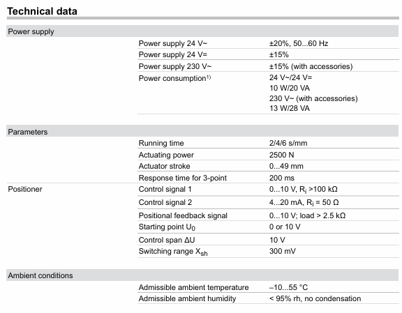
Key technical parameters
Category specific parameters
Power supply 24V~: ± 20%, 50... 60 Hz; 24V=± 15%; 230 V~(with accessories): ± 15%
Running performance and running time: 2/4/6 s/mm; Driving force: 2500 N; actuator stroke: 0... 49 mm; 3-point control response time: 200 ms
Signal specifications control signal 1: 0... 10 V, input resistance>100 k Ω; control signal 2: 4... 20 mA, input resistance 50 Ω; Position feedback signal: 0... 10 V, load>2.5 k Ω; starting voltage U0:0 or 10 V; control span Δ U: 10 V; Switching range Xsh: 300 mV
Permissible environmental temperature: -10... 55 ° C; Permissible environmental humidity:<95% RH (without condensation); Overvoltage category: III; Pollution level: III
Physical specification weight: 4.1 kg; compliant with EMC Directive 2014/30/EU (EN 61000-6-2, EN 61000-6-4) and Low Voltage Directive 2014/35/EU (EN 60730-1, EN 60730-2-14)
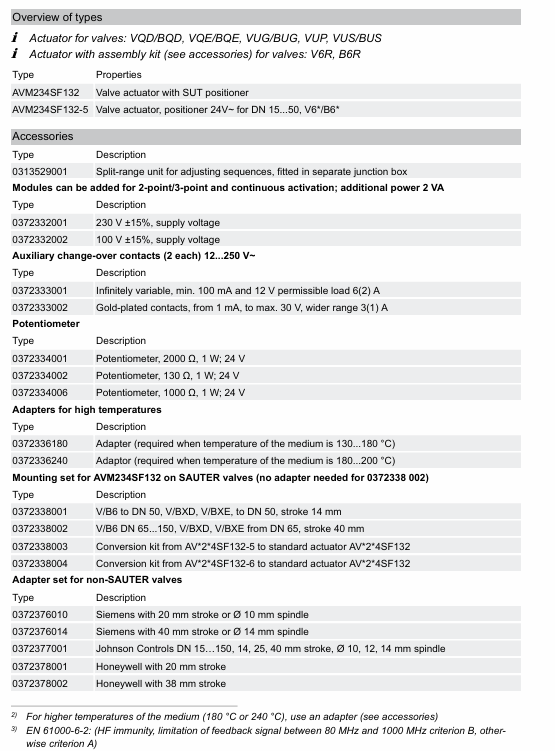
Product model and accessories
main models
AVM234SF132: Valve actuator with SUT locator.
AVM234SF132-5:24 V~Positioner actuator, suitable for V6 */B6 * valves with DN 15... 50.
Core accessories
|Accessory Type | Model and Function|
|Voltage divider unit | 0313529001: used for adjusting sequence, installed in an independent junction box, can add 2-point/3-point and continuous drive modules, with an additional power consumption of 2 VA|
|Power supply module | 0372332001:230 V ± 15% power supply; 0372332002:100 V ± 15% power supply|
|Auxiliary conversion contact | 0372333001: infinitely adjustable, minimum 100 mA, 12 V, allowable load 6 (2) A; 0372333002: Gold plated contacts, starting from 1 mA, maximum 30 V, load 3 (1) A|
|Potentiometer | 0372334001 (2000 Ω, 1 W, 24 V), 0372334002 (130 Ω, 1 W, 24 V), 037233406 (1000 Ω, 1 W, 24 V), of which 130 Ω is only used as a voltage divider|
|High temperature adapter | 0372336180: suitable for medium temperatures of 130... 180 ° C; 0372336240: suitable for medium temperatures of 180... 200 ° C|
|Installation and Conversion Kit | 0372338001 (compatible with V/B6 DN 15... 50, V/BXD/V/BXE DN 15... 50, stroke 14 mm), 0372338002 (compatible with V/B6 DN 65... 150, V/BXD/V/BXE DN 65+, stroke 40 mm, no additional adapter required), 0372338003/0372338004 (convert AV24SF132-5/-6 to standard actuator respectively)|
|Non SAUTER Valve Adapter | Compatible with Siemens (0372376010/0372376014), Johnson Controls (0372377001), Honeywell (0372378001/0372378002), ITT Dr ä ger (0372389001/0372389002), Frese (0510390052/0510390053) and other brand valves|
|Other accessories | 0372387001 (SAUTER Satchwell VZF1727 installation kit), 0386263001/0386263002 (M16 × 1.5/M20 × 1.5 cable thread connector), 0372461001 (AV × 2 × 4S mandatory operation accessory)|
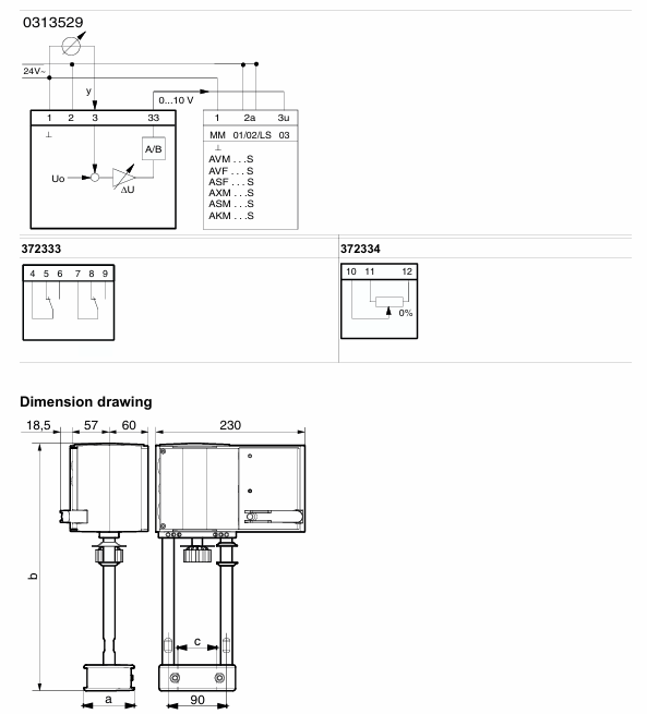
Working principle and operating instructions
Work mode selection
Continuous drive: Connect 0... 10 V/4... 20 mA signals, set the running time through S1/S2, set the flow characteristics through S3/S4, automatically initialize (connect the valve stem to the lower limit of the valve before detecting and saving the stroke at the upper limit), feedback signal corresponds to the effective stroke (0... 10 V corresponds to 0... 100% stroke), no need to reinitialize after power failure.
2-point control (OPEN/CLOSE): Connected by 2 wires at 24 V, terminal 1+2a is powered on, terminal 2b is powered on at 24 V, and the valve stem extends. After power-off, it returns to the opposite terminal position, without feature selection. Terminal 3i/3u/44 is not wired.
3-point control (OPEN/STOP/CLOSE): At 24 V, terminals 2a/2b can be moved to any position when powered on, 1+2b can extend the valve stem when powered on, 1+2a can retract when powered on, and the wiring can be changed to change the direction of travel without feature selection. Terminals 3i/3u/44 are not wired.
230 V/100... 110 V drive: accessory 0372332 is required. The locator works according to the controller output signal. When both 3u (voltage) and 3i (current) signals are present, high values take priority; There are two operating directions (when the signal increases, the 2a power supply valve stem extends and the 2b power supply valve stem retracts), and a partial range can be set for the boost unit.
Initialization and fault handling
Reinitialize: When powered on and there is a continuous signal from 3u/3i, the crankshaft will be unfolded and retracted twice within 4 seconds, the LED will flash red, and the feedback signal during initialization will be 0. The process will be executed with the shortest running time, and the unfolding of the crankshaft can be interrupted. It will take effect after completion.
Jam handling: Upon detecting a jam, attempt to overcome it within 90 seconds. If unsuccessful, set the feedback signal to 0 V. Once overcome, restore normal control.
Meaning of LED indicator light
|LED Status | Meaning|
|Two lights flashing red | Initialization in progress|
|The red light on the upper light is always on | reaching the upper limit or "off" position|
|The red light under the lamp is always on | reaching the lower limit or "open" position|
|The green light on the upper light is flashing | The actuator is running and moving towards the "off" position|
|The green light on the upper light is always on | The actuator stops, and the last running direction was "off"|
|The green light under the lamp is flashing | The actuator is running and moving towards the "open" position|
|The green light under the lamp is always on | The actuator stops, and the last running direction was "open"|
|No light on | No power supply (terminals 2a/2b have no power)|
|Two lights flashing alternately in red and green | The actuator is in manual mode|
Installation and usage precautions
Installation requirements
Prevent condensation and dripping water from entering the actuator along the valve stem; The valve is directly screwed onto the actuator without additional adjustment, and the actuator stem is in the middle position when it leaves the factory.
Outdoor installation requires additional wind and rain protection; Multiple actuators of the same type can be connected in parallel, and the cross-sectional area of the power cord needs to be selected according to the length and quantity of the cable (such as 5 parallel actuators, 50 m cable, recommended 1.5 mm ²).
The actuator can accommodate up to one 230 V module, one auxiliary accessory (auxiliary contact/potentiometer), and one voltage divider unit.
Temperature related requirements
When the temperature of the valve medium is ≤ 110 ° C, the maximum ambient temperature is 60 ° C; when the temperature of the medium is>110 ° C, the maximum ambient temperature is 55 ° C, otherwise a high-temperature adapter (0372336180) needs to be installed.
Corresponding high-temperature adapters are required for medium temperatures of 180 ° C and above, and the actuator column and valve stem may become hot with the increase of medium temperature, requiring attention to protection.
Compliance and Security
Only for the manufacturer's designated use, modification is prohibited, and relevant product specifications must be followed; If the control unit malfunctions and may cause damage, additional protective measures need to be taken.
Attention should be paid to the rated parameters when using auxiliary contacts. For example, if the gold-plated contact 0372333002 is used once below 10 mA or above 50 V, the gold plating will fail and can only be used in higher rated scenarios.
Disposal
Compliance with current local laws and regulations is required, and material related information can be found in the product's "Material and Environmental Statement".
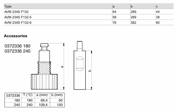
Size specifications
Actuator size (unit: mm)
|Model | a | b | c|
| AVM 234S F132 | 64 | 289 | 44 |
| AVM 234S F132-5 | 58 | 289 | 38 |
| AVM 234S F132-6 | 78 | 382 | 60 |
High temperature adapter size (unit: mm)
|Adapter model | Applicable temperature (° C) | a | b|
| 0372336180 | 180 | 69.4 | 60 |
| 0372336240 | 240 | 109.4 | 100 |
- YOKOGAWA
- Reliance
- ADVANCED
- SEW
- ProSoft
- WATLOW
- Kongsberg
- FANUC
- VSD
- DCS
- PLC
- man-machine
- Covid-19
- Energy and Gender
- Energy Access
- Renewable Integration
- Energy Subsidies
- Energy and Water
- Net zero emission
- Energy Security
- Critical Minerals
- A-B
- petroleum
- Mine scale
- Sewage treatment
- cement
- architecture
- Industrial information
- New energy
- Automobile market
- electricity
- Construction site
- HIMA
- ABB
- Rockwell
- Schneider Modicon
- Siemens
- xYCOM
- Yaskawa
- Woodward
- BOSCH Rexroth
- MOOG
- General Electric
- American NI
- Rolls-Royce
- CTI
- Honeywell
- EMERSON
- MAN
- GE
- TRICONEX
- Control Wave
- ALSTOM
- AMAT
- STUDER
- KONGSBERG
- MOTOROLA
- DANAHER MOTION
- Bentley
- Galil
- EATON
- MOLEX
- Triconex
- DEIF
- B&W
- ZYGO
- Aerotech
- DANFOSS
- KOLLMORGEN
- Beijer
- Endress+Hauser
- schneider
- Foxboro
- KB
- REXROTH
- YAMAHA
- Johnson
- Westinghouse
- WAGO
- TOSHIBA
- TEKTRONIX
- BENDER
- BMCM
- SMC
- HITACHI
- HIRSCHMANN
- XP POWER
- Baldor
- Meggitt
- SHINKAWA
- Other Brands
- UniOP
- KUKA
- IBA
-
Woodward 8272-796 - Real Power Sensor Module 115/230v-ac
-
Woodward 5463-873 - NetCon Output Module
-
Woodward 8271-567 - Load Sensor Module 120/208v-ac
-
Woodward Type UG-8 P/N 8522-300 EG - Governor R.P.M 1075-1650 With Motor Groschopp
-
WOODWARD 9905-971 REV J - LINKNET 16 CHANNEL DISCRETE INPUT MODULE
-
WOODWARD 8280-3014 - 723 PLUS DIGITAL CONTROL REV NEW
-
Woodward 505DE - Digital Control System
-
Woodward 5453-750 - Ethernet Interface FTM
-
Woodward 9907-018 Rev H - 2301A Load Sharing & Speed Control
-
WOODWARD 5420-1080 V4.3 - BOARD-PPA WITHBOX
-
Woodward b 8271-347SP - 2301 speed control
-
Woodward 9905-795 Rev B - Digital Synchronizer and Load Control
-
Woodward 9905-377 Rev. A - 2301A Load Sharing and Speed Control
-
WOODWARD 8272-582 - Generator speed control module
-
WOODWARD 9907-247 REV K - 828 DIGITAL CONTROL UNIT
-
WOODWARD 5466-353 REV C - NETCON MAIN CHASSIS TRANSCEIVER
-
Woodward Type UG-8 P/N 8524-708 - Governor 760-1560 Governor R.P.M
-
WOODWARD 9907-247 REV K - 828 DIGITAL CONTROL UNIT
-
WOODWARD 8440-1831 REV. H - EASYGEN3000 3200-5 - WITHOUT ACCESSORIES
-
WOODWARD 8444-1002 REV G - UMT1 MEASURING TRANSDUCERS
-
Woodward 5410-312C - Digital Marine Control Printed Circuit Board
-
Woodward 9905-799 REV F - Digital Synchronizer & Load Control , V#456
-
Woodward 9907-014 - 2301A for controller
-
Woodward Type UG-8 P/N B522-446 - Governor R.P.M 500-1200
-
WOODWARD 8272-221 REV.B - DIGITAL REFERENCE UNIT
-
Woodward 8901-037 - Booster Servomotor Single
-
WOODWARD 8444-1019 REV G - UMT 1 MEASURING TRANSDUCER
-
WOODWARD 1767-367 Z21 WK 0920702 - GOVERNOR MOTOR 2700 RPM KM 58-20 K 230V
-
WOODWARD 9905-972 Rev:G - LINKNET 6 CHANNEL 4-20mA OutPut
-
Woodward E8250-501 - Actuator Governor
-
LTI Drives CDF30.002.C0.7 Compact Servo Controller 08685963 DC 24V Industrial Module
-
LUST LTI Drives CDB32.008.W2.4.BR.PC1 Servo Drive Industrial Motion System
-
LUST LTI Drives CDB34.003.C2.4.PC1.H15 Servo Motor Driver Industrial Control Unit
-
LUST LTI Drives CDA32.004.C1.4.H08.B0 Servo Drive Mat. 3084456 Industrial Control
-
LUST LTI Drives CDE34.005.W2.2 Industrial Servo Drive Motion Control Unit
-
LUST LTI Drives CDA34.006.W3.0 Servo Drive Software V3.70-04 Industrial Controller
-
LTI Drives CDB32.004.C2.4.SH Servo Drive Compact Motion Controller
-
Woodward 9905-373 - Digital Synchronizer And Load Controller
-
WOODWARD MAGNETIC PICKUPS - Sensor
-
WOODWARD GCP-30 - Steuertafel for Industrial Regulator Genset Control Package
-
WOODWARD GOVERNOR 9907-1183 REV A - 505 ENHANCED TURBINE CONTROL
-
WOODWARD 9907-173 REV B - Module Load Sharing 120 Volt
-
WOODWARD 9907-014 - 2301A controller
-
Woodward 9905-029 - SPM-A Synchronizer Module Rev C
-
WOODWARD 8440-1799 EASYGEN-350 REV B - Genset Controller
-
WOODWARD 5466-258 REV M - SIMPLEX DISCRETE I/O MODULE
-
Woodward 8440-1884 C - Controller Easygen 2500-5
-
Woodward 8441-1153 - Monitoring Unit 250VAC
-
WOODWARD 8406-120 REV G - EGCP-2 DIGITAL CONTROL
-
Woodward 8273-584 - Atlas-ii Digital Control
-
Woodward 8272-582 - APM Motor Control 8272582
-
Woodward 9905-377 Rev. A - 2301A Load Sharing and Speed Control
-
WOODWARD 8272-517 - Pm Motor Control
-
WOODWARD 9905-797 REV.B - DIGITAL SYNCHRONIZER AND LOAD CONTROL DSLC-D
-
WOODWARD 8272-582 - APM MOTOR CONTROL
-
Woodward Seg FP2-8-24 - Emergency Power Telecommunications Module NP2
-
WOODWARD 2001-12E2U1B1S1A - Fuel Shut Off Valve Stop Solenoid Valve 2000-4505
-
Woodward 8440-1884 K - Genset Controller Easygen-2500-5
-
Woodward 9905-760 - Linknet Termination Module
-
Woodward 8404-009 - Proact Digital Plus Front Panel Rev. H
-
Woodward 8271-651 - Digital Speed Reference
-
Woodward 3077-474C - 8605895 5501-031 D Circuit Module
-
WOODWARD 5466-257 REV.-C - NETCON 5000 MODEL REMOTE TRANSCEIVER I/O MODULE
-
Woodward 8273-101 Rev: A - 2301D Digital Load Sharing and Speed Control
-
WOODWARD 8272-799 - 2301A SPEED CONTROL WITH REMOTE REFERENCE REV:C
-
Woodward 8272-517 - PM Motor Control
-
Woodward 8290-048 8290048 Rev. F - Generator Load Sensor
-
woodward 8273-1012 rev c - 2301e Load Sharing and Speed Control
-
WOODWARD 9905-797 - DIGITAL SYNCHRONIZER AND LOAD CONTROL FOR 3 PHASE GENERATORS
-
WOODWARD 8280-3014 - 723 PLUS DIGITAL CONTROL REV NEW
-
WOODWARD 8440-1884 REV G - GENSET CONTROLLER EASYGEN-2500-5/P1
-
Woodward 8272-683 K - Digital Reference
-
WOODWARD 9907-014 - SPEED CONTROL 2301A REV H
-
Woodward Type UG-8 P/N 037260 - Governor R.P.M 1075-1650 Motor KM58-20
-
WOODWARD 9905-970 - LINKNET 6 CHANNEL 100 OHM RTD Rev:J
-
Woodward 9907-1183 Rev C - Steam Turbine Digital SCREEN 505E Turbine Control
-
Woodward 8440-1614 - GCP-30 Genset Control Package, Rev: F, Type 1, E231544
-
Woodward DC11006-304-024 - ACTUOTOR DYNA ACTUATOR - BARBER-COLMAN
-
Woodward 9905-971 - LINKNET 6 CHANNEL 100 OHM RTD Rev:K
-
Woodward DYNK-10249 - Actuator Controller Kit - DYNA 2000
-
Woodward LR21035 - MFR1 MULTI FUNCTION RELAY REV F
-
Woodward 8440-1831 - EASYGEN 3200-5 P/N: REV. G Gererator Controller
-
Woodward 8272-516 - PM MOTOR CONTROL REV J
-
Woodward 8440-2080 - EASYGEN 2000 genset controller EASYGEN-2300-5/P1
-
Woodward 505DE - Digital Control System
-
Woodward 701 - Digital Speed Control 18-40 VDC 4-20 MA
-
Woodward 8440-1799 - EASYGEN-350 REV B
-
Woodward 8272-582 - Apm Motor Control 100-220v AC/DC
-
Woodward 5501-031 D - 3077-474C 8605895 Circuit Module
-
Woodward XD1-T - XD1T55SAT TRANSFORMER DIFFERENTIAL PROTECTION RELAY
-
Woodward 8272-517 - PM Motor Control 220vac
-
Woodward 8934-658 - Repair Kit UG8D Governor
-
Woodward 5437 18 - module netcon derivative analog rev.A
-
Woodward 8272-171 A - Pm Motor Control
-
Woodward MRN3-1/2 - SEG mains uncoupling relay MRN314D mains decoupling relay
-
Woodward 9905-373 - Digital Synchronizer and Load Control 18-40 VDC Rev P
-
Woodward 5431-640 C - Dual Dynamics 1000 Series Speed Control Module
-
Woodward 5501-031 D - 3077-474C 8605895 Circuit Module
-
Woodward 9907-247 - 828 DIGITAL CONTROL
-
Woodward 8440-1855-G - EASYGEN-2200-5 /P1 12/24VDC GENSET CONTROLLER
-
Woodward NC3-2-8 (NO) - GENERATOR CONTROLLER
-
Woodward 8271-467 K - 2301 LOAD SHARING AND SPEED CONTROL PART NO:
-
Woodward 8440-2177 A - SPM-D2-10 Digital Synchronising Controller
-
Woodward LXMG1614E-14-11 - CCFL and UV Lamps Inverter Module
-
Woodward 8270-990 - signal converter
-
Woodward 9905-068 - LOW VOLTAGE 2301A LOAD SHARING & SPEED CONTOL P/N:
-
Woodward 8901-051 - BOOSTER SERVOMOTOR, SINGLE CYLINDER, 2:1
-
Woodward 8444-1024 D - MWS4-55M CONTROL MODULE UNIT
-
Woodward 5448-914 - GCP-20 Genset Control GCP-20 REV D P/n:
-
Danfoss BHA-1 018-1942 - Hydraulic Actuator
-
Woodward 9905-001 L - SPM-A SYNCHRONIZER
-
Woodward 5464-850 - Module
-
Woodward 5501-371 - Micronet Simplex Mpu Aio Rev C
-
Woodward 8272-132 B - POWER SENSOR
-
Woodward 9907-028 - SPM-A Synchronizer
-
Woodward SA-3678-AM-2 - Overspeed Electric Governor, Model ESSE2-AM
-
Woodward E8250-502 - GOVERNOR ACTUATOR
-
Woodward 8440-1884 J - Controller EASYGEN-2500-5
-
Woodward 5441-693 - DIGITAL I/O MODULE -MISSING PART
-
Woodward SA-4450 - Speed Controller APECS 3100 For Magnetic Pickup
-
Woodward 9903-466 - 701 DIGITAL SPEED CONTROL REV G
-
Woodward 1765-843 - Governor Speed Adjusting Motor P/N Type: SMM40 220V AC 50/60Hz
-
Woodward 9905-760 - Linknet Termination Module
-
Woodward 9907-247 - 828 DIGITAL CONTROL UNIT REV K
-
Woodward 5484-721 - motor
-
Woodward 8440-1734 - MFR-2 Rev.A Multi Function Relay MFR-2
-
Woodward CSC3SUWA - Controller
-
Woodward 8440-1667 - REV B SPM-D1010B/XN

K-JIANG

Add: Jimei North Road, Jimei District, Xiamen, Fujian, China
Tell:+86-15305925923