
K-WANG


Yokogawa ROTOMETER RAMC Metal Variable Area Flow Meter
Yokogawa ROTOMETER RAMC Metal Variable Area Flow Meter
Positioning and core use
The dedicated user manual for Yokogawa ROTOMETER RAMC series metal variable area flow meters is suitable for volumetric/mass flow measurement of liquids and gases, especially for turbulent, opaque or corrosive fluid scenarios. The core uses float magnetic transmission to achieve flow indication and supports extended functions such as electronic transmitters and limit switches.
Core principles and structure of the product
1. Measurement principle
RAMC is a variable area flowmeter that operates based on the principle of "float force balance"
The fluid flows through the conical measuring tube from bottom to top, generating upward lift on the float;
The float rises to the equilibrium position of "lift=gravity+buoyancy", and its height is proportional to the flow rate;
The float is equipped with a built-in magnet, which drives the indicator pointer through magnetic transmission or triggers the electronic transmitter to output a 4-20mA signal/limit switch action.
Key feature: Within the "viscosity independent range" (fluid viscosity below a specific value), flow rate is only related to float height; When exceeding this range, the influence of viscosity on measurement needs to be considered, and the calibration scale and EEPROM need to be recalculated by the manufacturer.
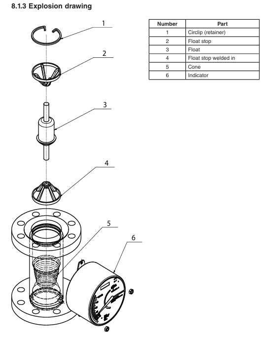
2. Product structure and core components
Component Name Function Description
The conical measuring tube provides a float rising channel, and the material is selected according to the corrosiveness of the fluid (such as stainless steel 1.4404/316L, PTFE)
Float core sensing element, built-in magnet, material adapted to fluid characteristics (such as corrosion-resistant alloy)
Indicator mechanical pointer indicates flow rate, optional LCD digital display (displaying flow rate, cumulative value, percentage, etc.)
The electronic transmitter (- E/- J type) converts the float position into a 4-20mA analog signal, while the - J type supports HART 7 communication
Limit switch (/K1-/K10 options) realizes flow upper and lower limit alarm, supporting standard type (/K1-/K3) and fail safe type (/K6-/K10)
Calibration EEPROM stores customized calibration data (such as fluid density, temperature, viscosity parameters), corresponding one-to-one with the measuring tube
Installation and wiring specifications
1. Preparation before installation and environmental requirements
Environmental restrictions:
Temperature: -40 ° C~+70 ° C (standard), -20 ° C~+60 ° C (explosion-proof type);
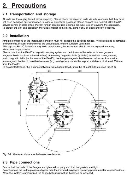
Avoid strong vibrations, corrosive environments (if necessary, choose high anti-corrosion coating shells), and strong magnetic field interference (keep a distance from solenoid valves, etc. Ferromagnetic objects should be kept away from ≥ 250mm);
The distance between adjacent RAMCs should be ≥ 300mm to prevent mutual interference of magnetic fields.
Pipeline requirements:
It must be installed vertically, with the fluid flow direction being "downward and upward", and the flanges should be aligned parallel to avoid pipeline stress;
For models with a nominal diameter greater than RAMC08, it is necessary to reserve a straight pipe section for the first 5 times the nominal diameter and a straight pipe section for the last 3 times the nominal diameter;
If the fluid may contaminate the measuring tube, it is recommended to install a bypass pipeline for easy disassembly and cleaning of the equipment.
2. Pipeline connection and wiring operation
Flange connection: Supports EN, ASME and other standard flanges, and bolt torque must strictly follow the specifications, such as DN15 PN40 flange (EN 1092-1) torque of 9.8 Nm, DN50 PN40 flange torque of 57 Nm; PTFE lined flanges require additional attention to sealing performance to avoid fluid leakage.
Wiring specifications:
Cable sealing sleeve: Suitable for cables with a diameter of 6-9mm. If not in use, M16 × 1.5 (shell 90 type) or M20 × 1.5 (shell 91 type) blind plug sealing is required for the entrance;
Signal and power separation: Analog signals (4-20mA), digital communication (HART), and power cables need to be wired separately to avoid interference;
Grounding requirements: The protective grounding (PE terminal) must be firmly connected, with a grounding resistance of ≤ 100 Ω, and an additional external grounding clamp is required for the 91 type shell.
Core functions and parameter configuration
1. Operation of electronic transmitter (- E/- J type)
(1) Basic functions and parameter settings
The electronic transmitter supports functions such as flow display, cumulative value statistics, 4-20mA output calibration, etc. It can be configured through two operation keys (up key "exit", down key "switch menu", combination key "confirm"). The core parameters are as follows:
Function Description of Key Setting Items for Parameter Categories
Display function (F11) default display of flow/cumulative value/percentage/temperature cumulative value, switchable units (such as m ³/h, L/min, kg/s)
Unit setting (F12/F13): Volume/mass unit+time unit. The European version supports m ³, Nm ³, kg, etc., while the American version (/A12 option) supports gal, scf, etc
Damping setting (F21): Smooth output signal for 0/1/5/10 seconds to reduce the impact of flow fluctuations, with a default of 1 second
Current output (F3-) 4-20mA/0-20mA switch 2-wire system default 4-20mA, adjustable zero point (F32) and range (F33), 20 μ A per step
Fault detection (F4-) error code displayed as "08" indicates that the float is stuck and needs to be cleaned or automatically zeroed (F74)
Float stuck detection (F7-) on/off, monitoring lower limit (5%/15%/30% Qmax), monitoring time 5/15 minutes optional. If there is no signal fluctuation beyond the deadline, a fault alarm will be triggered
(2) HART 7 communication (- J type exclusive)
Communication features: Supports 2-wire 4-20mA overlay with HART signal, enables remote parameter configuration and data reading (such as real-time flow, cumulative value, diagnostic information), supports multi slave mode (up to 63 devices), and can set polling address 1-63.
Core functions:
Process variable monitoring: real-time reading of flow rate, temperature, current output, etc;
Fault diagnosis: detect RAM errors, ADC faults, EEPROM anomalies, etc;
Burst mode: Continuously sending specified data (such as traffic+cumulative value) to reduce communication latency;
Trend configuration: Record 12 sets of historical data, with adjustable sampling intervals of 1-2 hours.
2. Limit switch (/K1-/K10 options)
Type and Function:
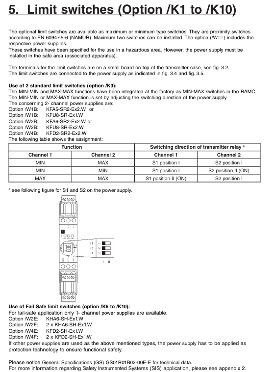
Standard type (/K1-/K3): Supports MAX/MIN dual contacts and complies with EN 60947-5-6 (NAMUR) standard;
Fault safe type (/K6-/K10): When power is cut off, the contacts automatically switch to a safe state and require a dedicated power supply (such as/K2E,/W4F).
Parameter configuration: Set the MIN-MAX/MIN-MIN/MAX-MAX function by switching the direction of the power supply. For example, when the K3 option is paired with the W2B power supply, the S1/S2 relay position determines the contact logic.
Explosion proof certification and safety regulations
1. Explosion proof type and applicable scenarios
RAMC provides two types of explosion-proof designs: intrinsic safety (Ex ia) and explosion-proof (Ex db), covering major certification systems worldwide. The core parameters are as follows:
Certification Type Model Options Explosion proof Mark Applicable Area Key Parameters (Electronic Transmitter)
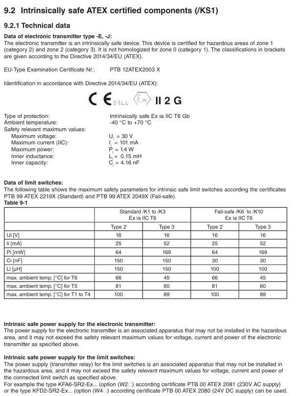
ATEX/KS1 (intrinsic safety) Ex ia IIC T6 Gb Zone 1/2 (gas), Zone 21/22 (dust) Ui=30V, Ii=101mA, Pi=1.4W
IECEx/ES1 (Intrinsic Safety) Ex ia IIC T6 Gb Global Explosion proof Zone Li=0.15mH, Ci=4.16nF
NEPSI (China)/NS1 (Intrinsic Safety) Ex ia IIC T6 Gb Explosion proof Area Environmental Temperature in China -40 ° C~+70 ° C
FM/UL (US Canada)/FS1 (Intrinsic Safety) Class I Div1 GP A-D T6 US Canada Zone 1/Zone 2 Vi=30V, Ii=100mA, Pi=1.4W
EAC (Eurasian Economic Union)/GS1 (Explosion proof+Dust) Ex db IIC T6 Gb/Ex tb IIIC T80 ° C Db Eurasian Union Explosion proof Area Surface Temperature ≤ 80 ° C (T6)
2. Explosion proof installation and operation taboos
Intrinsic safety requirements:
The power supply must be a certified associated device (such as KFA6-SR2-Ex2. W) installed in a safe area;
The cable capacitance/inductance should be ≤ Ci/Li (e.g. Ci=4.16nF, Li=0.15mH) to avoid safety risks caused by exceeding the limit.
Explosion proof type requirements:
Power off and wait for 15 minutes before opening the lid to ensure the safety of the internal gas;
The cable sealing sleeve must comply with the IEC 60079-1 standard and be sealed with certified blind plugs for entry purposes;
When the shell is damaged (such as the observation window breaking), it should be immediately stopped to avoid the failure of explosion-proof performance.
Maintenance and troubleshooting
1. Daily maintenance and regular inspections
Routine inspection (weekly):
Pointer/display screen: Confirm that the flow indication matches the actual working conditions without any jamming or jumping;
Sealing state: The flange and cable sealing sleeve have no leakage, and the shell has no corrosion;
Explosion proof mark: The label is clear, without wear or detachment.
Regular maintenance (every 6 months):
Cleaning: The measuring tube and float need to be disassembled and cleaned (avoiding the use of corrosive solvents), and the magnetic properties of the float should be checked for normal operation;
Calibration: The electronic transmitter needs to be verified for 4-20mA output accuracy through a HART communicator, and the limit switch needs to be tested for contact action reliability;
Grounding inspection: The grounding resistance is ≤ 100 Ω, and the grounding terminal is not loose.
2. Common faults and troubleshooting
Possible causes and solutions for the fault phenomenon
The pointer is unresponsive/stuck, the float is stuck by impurities, and the inner wall of the measuring tube is scaled. Disassemble and clean the float and measuring tube, and replace the float if necessary
Electronic transmitter has no output power supply fault, calibration EEPROM is missing, wiring is loose. Check power supply (24VDC ± 10%), reinsert EEPROM, and tighten wiring terminals
HART communication failure, load resistance not between 250-600 Ω, pole address conflict, adjust load resistance, reset unique pole address (1-63)
The flow indication deviation is large, and the viscosity/density of the fluid does not match the calibration value. The wear of the float provides new fluid parameters, and the manufacturer recalculates the scale; Replace the worn float
Improper threshold setting for triggering limit switch misoperation, recalibration of switch threshold due to magnetic field interference (such as 5% Qmax), and staying away from strong magnetic field sources
Application of Safety Instrumented System (SIS)
1. Applicable models and safety functions
RAMC only comes with fail safe limit switches (V1) and standard limit switches (V2), which can be used for SIS as flow monitoring components connected to safety instrument functions (SIF). The core realizes "flow over limit alarm" or "emergency cut-off trigger", and supports SIL1-SIL2 levels (depending on configuration and verification cycle).
2. Key SIS requirements
Verification cycle: It should be set according to safety integrity requirements, with a recommended duration of 1-5 years. The verification coverage rate should be ≥ 99%, and the verification results should be recorded (such as forcing the float to trigger the MAX/MIN threshold and verifying the switch action);
Reliability data: V1 type (fail safe switch) SFF=61%, MTBF=530 years, V2 type (standard switch) SFF=42%, MTBF=401 years. Detailed FMEDA reports can be obtained from the manufacturer;
Lifecycle: Designed for a lifespan of 10 years, if exceeded, reliability needs to be reassessed or core components such as measuring tubes and floats need to be replaced.
Compliance and Disposal Standards
1. Compliance with PED Pressure Equipment Directive
RAMC complies with 2014/68/EU (PED), the measuring tube is classified as "pipeline", the heating element (/T1-/T6 options) is classified as "container", fluid group 1-2, module H, and some models (such as RAMC03-15) belong to Class III pressure equipment and need to comply with pressure temperature ratings (such as stainless steel material -196 ° C~370 ° C, PTFE material -80 ° C~130 ° C).
2. Requirements for abandonment and return to factory
Decontamination treatment: After coming into contact with harmful fluids, the equipment should be thoroughly cleaned to avoid residual corrosion or toxicity. A "Decontamination Declaration" should be submitted when returning to the factory;
Environmental disposal: It belongs to WEEE equipment (2012/19/EC) and is prohibited from being mixed with municipal waste. It must be collected by professional institutions or returned to designated outlets in Yokogawa for disposal.
Summary and selection suggestions
1. Core advantages
Wide applicability scenarios: Supports corrosive, opaque, turbulent fluids, temperature range -196 ° C~370 ° C, pressure range PN16~PN100;
Flexible function expansion: optional electronic transmitter (HART communication), limit switch (fail safe), explosion-proof certification (global major system);
Low maintenance cost: The measuring tube and float are made of durable materials (such as 316L stainless steel), with no vulnerable parts. Calibration only requires replacing the EEPROM and scale.
2. Key parameters for selection
Fluid characteristics: Select the material of the measuring tube/float based on density, viscosity, and corrosiveness (such as PTFE for strong corrosion and stainless steel for conventional fluids);
Explosion proof requirements: Hazardous areas require matching certification types (such as China Select/NS1, US Canada Select/FS1);
Signal output: Remote monitoring should select the - J type (HART), only local indication should select the - T type, and alarm control should be equipped with/K series limit switches.
- YOKOGAWA
- Reliance
- ADVANCED
- SEW
- ProSoft
- WATLOW
- Kongsberg
- FANUC
- VSD
- DCS
- PLC
- man-machine
- Covid-19
- Energy and Gender
- Energy Access
- Renewable Integration
- Energy Subsidies
- Energy and Water
- Net zero emission
- Energy Security
- Critical Minerals
- A-B
- petroleum
- Mine scale
- Sewage treatment
- cement
- architecture
- Industrial information
- New energy
- Automobile market
- electricity
- Construction site
- HIMA
- ABB
- Rockwell
- Schneider Modicon
- Siemens
- xYCOM
- Yaskawa
- Woodward
- BOSCH Rexroth
- MOOG
- General Electric
- American NI
- Rolls-Royce
- CTI
- Honeywell
- EMERSON
- MAN
- GE
- TRICONEX
- Control Wave
- ALSTOM
- AMAT
- STUDER
- KONGSBERG
- MOTOROLA
- DANAHER MOTION
- Bentley
- Galil
- EATON
- MOLEX
- Triconex
- DEIF
- B&W
- ZYGO
- Aerotech
- DANFOSS
- KOLLMORGEN
- Beijer
- Endress+Hauser
- schneider
- Foxboro
- KB
- REXROTH
- YAMAHA
- Johnson
- Westinghouse
- WAGO
- TOSHIBA
- TEKTRONIX
- BENDER
- BMCM
- SMC
- HITACHI
- HIRSCHMANN
- XP POWER
- Baldor
- Meggitt
- SHINKAWA
- Other Brands
- UniOP
- KUKA
- IBA
- Beckhoff
-
LTI SC52.0040.0012.0000.0 - Servo Drive
-
Lti SC52.0040.0012.0000.0 - Servo Drive
-
Milton Industries LTI Tool By Milton LT1240 - 1/2" Drive Lugnut Remover
-
LTi Drives SO84.200.P030.0000.0-W - Servo Spindle Drive
-
LTI DRIVES LSP08-035-320-30-B0R1PY170 - Servo Motor
-
LTI DRIVES SE84.200.SC00.0001.0-W - Servo Drive
-
Lust CDE34.005.W2.2 - Lti Drives Controller
-
LTi SO84.012.0030.0011.2 - ServoOne Servo Drive
-
LTi Drives SO CM-P.0010.11.00.0 - Servo Drive Controller
-
LTi CDE34.017.W3.0 - Servo Drive
-
LTI Drives CDB32.004, C2.0,SH - Positioning Controller
-
LUST CM-CAN1 - LTi DRIVES Communication Module
-
LTi SO84.012.1030.0000.2 - Servo Drive
-
LTI MOOG CDE54.044 - PITCHMASTER FREQUENCY CONVERTER 181-01019
-
MOOG LTI 181-01019 CDE54.044 - PITCHMASTER FREQUENCY CONVERTER
-
Lust LTi Drives CDE34.010,D2.0 - Servo Drive Controller
-
LTI SO84.032.0003.0101.2 - Servo Drive
-
Seagate 9CC132-302 Harris LTI-CS IRT-34-0021-01 - Hard Drive 160GB
-
LTI SO84.032.0003.0001.2 - Servo Drive
-
LTI SO24.007.0070.0000.1 - SERVO CONTROLLER
-
LTi drive CDA32.003.C3.0.H05-01.PC1 - Servo Drive
-
LTI SO84.016.0030.0000.2 - SERVO CONTROLLER
-
LUST LTI CD A34.008,W1.4, BR - SERVO DRIVE
-
MOOG LTI 181-01019 CDE54.044 - PITCHMASTER FREQUENCY CONVERTER
-
LTI MOOG 181-01019 - PITCH Master Servo Drive CDE54.044
-
LTI SERVO ONE SO84.045.0030.0001.2-W - Drive
-
LUST LTi SO84.032.0040.0000.2 - SERVO ONE DRIVE
-
LTi Drives LSH-074-2-30-3 20/T1,G6.1M - SERVO MOTOR
-
LTI SO84.016.0000.0101.2 - servo drive
-
LTI SA54.0550.0033.0000.0 - Servo Drive
-
LTI SA54.0550.0033.0000.0 - Servo Drive
-
LTI LT 4850 - 3/8" Drive 3-Pc Twist Socket Transmission Drain Plug Removal System
-
LTI Tools LT4400-30 Lock Technology - 3/4" Twist Socket 1/2" Drive Lugnut Remover
-
LTI Tools LT-1400C - 1/2 Drive Wheel Torque Extension Tool
-
LTI Tools LT1250 - 1/2" Drive Dual Sided Socket Lug Nut Remover Tool
-
LTI SO84.032.0003.0101.2 - Servo Drive
-
LTI MOOG 181-01019 - PITCH Master Servo Drive CDE54.044
-
MOOG LTI 181-01019 CDE54.044 - PITCHMASTER FREQUENCY CONVERTER
-
MOOG LTI 181-01019 CDE54.044 - PITCHMASTER FREQUENCY CONVERTER
-
MOOG LTI 181-01019 CDE54.044 - PITCHMASTER FREQUENCY CONVERTER
-
LTI SA54.0550.0033.0000.0 - Servo Drive
-
LTI Tools LT-4800 - 7 Piece Twist Socket 3/8" Drive Oil Drain Plug Removal Set
-
LTI SA54.0550.0033.0000.0 - Servo Drive
-
LTI Drive SO24.007.00300000.0 - Servo Drive
-
LTI TOOLS LTI 1400-I - Drive Wheel Torque Extension
-
LTI Tools LT4400-3 - 3/4" 19mm Twist Socket 1/2" Drive Lugnut
-
LTI TOOLS LTI 1400-BB - Drive Wheel Torque Extension
-
LTI SO84.032.0003.0101.2 - Servo Drive
-
LTI Tools LT-4512 - 3/8" Drive 12mm Twist Socket
-
LTI MOTION Luster SO84.032.0003.0001.2 - Servo Drive
-
LTI Tool By Milton LT1600P - 1" Drive Torx Stick
-
LTI Lust VF1424L,HF,OP2,S56 - Variable Frequency Drive
-
LUST CDA32.004,C1.4,H08,B0 - SERVO DFRIVE CM-CAN1 Module
-
LTI SO84.045.0002.0001.2-W - Drive
-
LTI Lust VF1404M,C9,PT1,BR1 - Inverter Type VF1404M
-
LTI SA54.0550.0033.0000.0 - Servo Drive
-
LTI Tools LT-1400C - 1/2" Drive Wheel Torque Extension
-
Lust LTI DRiVES CDA32.006, C3.0, H09 - Variateur De Fr茅quence Frequency Inverter
-
LTI MOOG CDE54.044 - PITCH master SERVO DRIVE
-
LTI MOOG CDE54.044 - PITCH master SERVO DRIVE
-
LTI SO84.143.0020.0101.2-W - servo drive
-
LTI MOTION SC34.0200.0011.0000.0 - Servo drives
-
LTI SO84.032.0003.0001.2 - Servo Drive
-
LTI DRIVES GmbH MS100 - Assembly Set Mounting Kit
-
LTI SO84.032.0003.0001.2 - Servo Drive
-
LTI SO84.032.0003.0001.2 - Servo Drive
-
LTI MOTION SO84.032.0003.0101.2 - servo drive
-
LTI SO84.032.0003.0101.2 - Servo Drive
-
LTI MOOG CDE54.044 - PITCH master SERVO DRIVE
-
LTI MOTION CDE32.004.C2.4 - Servo drives
-
LTI CDD34.032锛學x.x锛孊R锛孭C1 - Servo Drive
-
Lust LTI DRiVES CDA32.006, C3.0, H09 - Inversor De Frecuencia Frequency Inverter
-
Lust SO84.008.0030.1000.0 - Servo One LTi Drive
-
LTI MOTION SO84.032.0003.0101.2 - Servo drives
-
LUST LTi CDA32.004,C1.4 - SERVO DRIVE
-
LTI MOOG CDE54.044 - PITCH Master SERVO DRIVE
-
LTI KEBA CDB32.004 C2.7, SH - PN: 08673530 Frequency Inverter
-
LTI Tools LT-1400C - 1/2" Drive Wheel Torque Extension
-
LTI LT1400-E - 1/2" Drive Wheel Torque Extension
-
LTI MOOG 181-01019 - PITCH master SERVO DRIVE CDE54.044
-
LTI LSN-097-0510-30-560/T1 - Actuator Motor
-
LTI Tools LT 4800 - 7 Piece 3/8" Drive Twist Socket Oil Drain Plug Removal System
-
LTI DRIVES GmbH MS100 - MONTAGESET Assembly Set Mounting Kit
-
Lti SC52.0040.0012.0000.0 - Servo Drive
-
LTI DRIVES GmbH MS100 - Juego De Montaje Assembly Set Mounting Kit
-
LTi DSM4-14.2-21R83-200 - Drives servomoteur Servo Motor
-
MOOG CDE 54.044.GDA - Pitch Master Industrielle Turbine Lti Drive
-
LTI SO24.004.0030.1000.0 - Servo Drive Controller
-
Lti MOOG CDE54.044 - Pitch Master Servo Drive
-
Lust LTI DRiVES CDA32.006, C3.0, H09 - Inverter
-
LTI MOTION GMBH CDB34.006,W3.0,PC1,H39 - Frequency inverter
-
LTI SO84.032.0003.0001.2 - Servo Drive
-
MOOG CDE 54.044.D - Pitch Master Industrielle Turbine Lti Drive
-
LTI TOOLS LT-1460 - 1/2" DRIVE WHEEL TORQUE EXTENSION KIT 5 PIECE SET
-
Lust Cdb32.003, C2.4 - Lti Drives Servoregulador Frecuencia Servo Controller Inverter
-
Lust LTI DRIVES CDA32.006, C3.0, H09 - Frequency Inverter
-
Lust Lti SO82.004.0030.0000.2 - Servo Drive
-
LTI MOTION SC34.0200.0011.0000.0-SL - Servo drives
-
LTI MOTION SA54.0075.0033.0000.0 - Servo drives
-
LTI MOTION SC32.0075.1011.0000.0 - Servo drives
-
LTI Servo-One Junior SO22.006.0080.1000.0 - Servo Controller Servoregler
-
LUST CDA32.004, C1.4, H08, B0 - Servo Drive & LTI CM-CAN1 Module
-
LTI DRIVES LSP08-035-320-30-B0R1PY170 - Servo Motor
-
LUST LTI CDA32.004,C1.4.H08.B0 - SERVO CONTROLLER DRIVES
-
LUST LTi DRiVES CDS44.072LC1.2 - Servo Drive
-
Lti Servo-One Junior SO22.006.0082.1000.0 - Servo Controller Servoregler
-
LUST CDA32.008,C2.0,HF - Lti DRIVES Spindle Drive Inverter
-
LTI SO22.003.0082.0000.0 - Servo Drives One junior Servo Controller Servoregler
-
Lust Lti Drives CM-CAN1 - Communication Module
-
LUST Lti Drives Vf1202s, G8, I6 - Frequency Inverter Drive
-
LTI DRIVES BR-090.03.540.UR.H38 - Bremswiderstand Brake Resistor
-
LTi DRIVES PM-E40.2DRA054P - Wind Turbine Pitch Control Inverter
-
LTi Drives GmbH br-110.01.540-UR - Brake Resistor
-
LTI Drives LSN-097-0960-30-0560/T1,S4,B - Servo Motor
-
LUST CDA34.006.C2.0 - LTI Drives Servoregler
-
LUST LTI DRIVES SERVO ONE JUNIOR SO24.002.0020.0000.1 - Servo Drive Controller
-
LTI MOTION SO84.032.0003.0001.2 - Servo drives
-
LTI DDTD750V2-120 - IBOP ACTUATOR CYLINDER FOR TOP DRIVE
-
LTI CDE32.004, C2.4 - SERVO DRIVE
-
LUST LTI DRIVES CDD34.017 W3.4PC1 - Servo Drive Controller
-
LTI CDA3208,C3,0,HF - AC SERVO DRIVE
-
LUST LTI DRIVES LSH-074-3-30-560/T1,G6.1S - SERVO MOTOR
-
LUST Lti CDB32.004.C2.4.SH - AC Servo Drive
-
LTi CDA32.006, C3.0, H09 - Servo Drive
-
LTI SO22.003.0010.0000.0 - Servo Drive Servo one junior Servoregler Controller
-
LTi Drives DSM4-14.2-21R83-200 - Servo Motor
-
LUST Lti Drives Lsh-097-1-30-560/T1, 1R - Servomotor
-
LTI 1237 - 7 Piece 1/2" Drive Flip Socket Set

K-JIANG

Add: Jimei North Road, Jimei District, Xiamen, Fujian, China
Tell:+86-15305925923