
K-WANG


Yokogawa ROTAMASS TI Coriolis Mass Flow Meter
Yokogawa ROTAMASS TI Coriolis Mass Flow Meter
Basic Information
Focusing on the application scenarios of SIS equipment, clarifying the responsibilities of users in installation, operation, maintenance and other aspects, covering key contents such as verification testing, maintenance and replacement, reliability data, etc., to ensure that the equipment maintains the design safety level.
SIS application core requirements
(1) Safety functions and signal transmission
Function positioning: Supports HART communication and can be used as a mass flow rate, fluid density, and fluid temperature measurement component in SIS, equipped with 1-2 4-20mA analog outputs and other I/O interfaces.
Signal connection: The signal needs to be transmitted to the logic solver of SIS (such as safety PLC/DCS) through 4-20mA output; The fault alarm mechanism is "simulated current out of range", which needs to be connected to enable the automatic diagnostic function of the device.
(2) Key technical parameters
Specific requirements for parameter categories
The safety accuracy is set at 2%, which means that internal component failures that result in measurement errors ≥ 2% will be included in the equipment failure rate
Diagnostic response time amplitude error: Report within 3 minutes after the fault occurs; Other errors (such as frequency errors, signal failures): reported within 7 seconds
Generate a valid signal within 20 seconds after powering on the startup time
The expected service life is 10 years, and only reliability data within this period is valid; After more than 10 years, the equipment failure rate may increase, and the safety integrity level (SIL) calculation results based on the original data may become invalid
(3) Set up and validate testing
Device Settings
During installation, it is necessary to configure the engineering unit parameters through a field communicator or display, and verify the correctness of the parameters (which can be read from the local display or checked for actual calibration of the equipment).
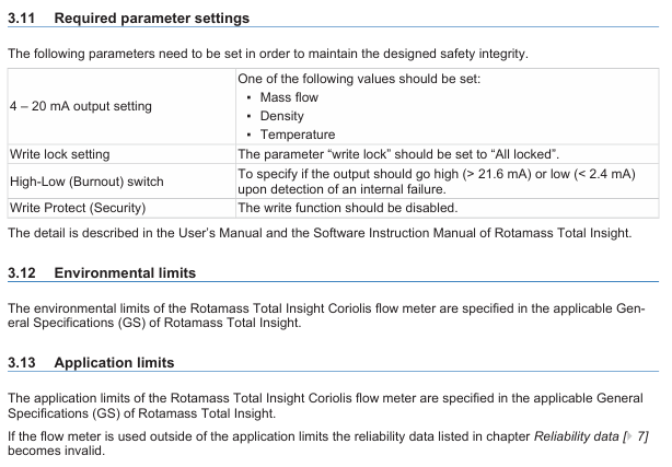
Key parameters need to be set according to the following requirements to maintain safety integrity:
|Parameter Category | Setting Requirements|
|4-20mA output | Select one of "Mass Flow", "Density", or "Temperature"|
|Write lock | Set to "All locked"|
|High Low (Burnout) switch | Specify the output current state in case of internal fault (High:>21.6mA; Low:<2.4mA)|
|Write Protect | Disable write function|
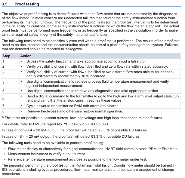
Proof Testing
Purpose: To detect faults that have not been detected by the equipment's self diagnosis (especially undetected faults that may cause safety instrument function (SIF) failure), the testing frequency should be determined based on the reliability calculation results of SIF, and the actual execution frequency should not be lower than the calculation requirements.
Test steps:
|Step | Operation Content|
|1 | Bypass safety function, take measures to avoid accidental tripping|
|2 | Verify the rationality of the output current (in compliance with the specified accuracy) when the flow tube is full and in a zero flow state|
|3 | Verify the rationality of the output current when the flow tube is filled with two different flow rates (which can be independently estimated with an accuracy of about 10%)|
|4 | Read the temperature measurement value of the process fluid through digital communication and compare it with the independent measurement value for verification|
|5 | Read diagnostic information through digital communication and take corresponding measures|
|6 | Send digital commands to the transmitter to enter the high and low alarm level output state, verify whether the analog current reaches the corresponding value (test static current, low loop voltage, high loop impedance related faults)|
|7 | Restart the transmitter power supply and clear the RAM soft error|
|8 | Release bypass and restore normal operation|
Detection effect: Both non intrinsic safety (non IS) and intrinsic safety (IS) 4-20mA outputs can detect 93.3% of potential hazard undetected (DU) faults.
Required tools: device display (or digital communication tools such as HART field communicator, PRM, FieldMate, etc.), output current verification instrument, reference temperature measurement tool close to the tested device.
Personnel requirements: Testers must receive SIS operation training, master bypass processes, equipment maintenance, and company change management processes.
(4) Repair, replacement, and firmware update
Repair and replacement: If online repair is required, bypass the equipment first and establish a compliant bypass process; Maintenance/replacement personnel need to have sufficient skills. If maintenance is required, please contact the Yokogawa sales office.
Firmware update: Only executed by the factory, users do not need to operate on their own, and after the update, they need to fulfill relevant responsibilities according to the replacement process.
(5) Reliability, Environment, and Application Limitations
Reliability data
Detailed Failure Mode, Effects, and Diagnostic Analysis (FMEDA) report (No. YEC 20-02-160 R002 V3R1) can be obtained from Yokogawa, including all failure rates and failure modes.
The device is suitable for "Low Demand Mode" (long average interval between hazardous conditions).
SIL certification: The highest certification under a single (1oo1) configuration is SIL2 (calculated based on the average failure probability (PFDavg) of the entire SIF); The highest certification for device development process is SIL3. When configuring redundancy (hardware fault tolerance level 1), the PFDavg calculation results of the entire SIF can be used for SIL3 scenarios. It is recommended to use a 2% common factor coefficient (β - factor) for redundant configuration.
Environmental and application limitations: The environmental and application limitations of the device must comply with the General Specification (GS) of ROTAMASS Total Insight; If the application limit is exceeded, the reliability data will be invalidated.
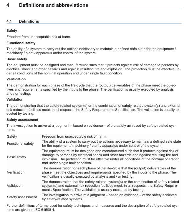
Definition and Abbreviations
Core definition: Clearly define terms such as "Safety", "Functional safety", "Basic safety", "Verification", "Validation", "Safety assessment", etc., in accordance with the relevant interpretations of IEC 61508-4 standard.
Key abbreviations:
|Abbreviation | Full name and description|
|DU | Dangerous Undetected|
|FMEDA | Failure Mode, Effects and Diagnostic Analysis|
|IS | Intrinsically safe explosion proof|
|PFDavg | Average Probability of Failure on Demand|
|PLC/DCS | Programmable Logic Controller/Distributed Control System|
|PRM | Plant Resource Manager|
|SIF | Safety Instrumented Function|
|SIL | Safety Integrity Level|
|SIS | Safety Instrumented System|
- YOKOGAWA
- Reliance
- ADVANCED
- SEW
- ProSoft
- WATLOW
- Kongsberg
- FANUC
- VSD
- DCS
- PLC
- man-machine
- Covid-19
- Energy and Gender
- Energy Access
- Renewable Integration
- Energy Subsidies
- Energy and Water
- Net zero emission
- Energy Security
- Critical Minerals
- A-B
- petroleum
- Mine scale
- Sewage treatment
- cement
- architecture
- Industrial information
- New energy
- Automobile market
- electricity
- Construction site
- HIMA
- ABB
- Rockwell
- Schneider Modicon
- Siemens
- xYCOM
- Yaskawa
- Woodward
- BOSCH Rexroth
- MOOG
- General Electric
- American NI
- Rolls-Royce
- CTI
- Honeywell
- EMERSON
- MAN
- GE
- TRICONEX
- Control Wave
- ALSTOM
- AMAT
- STUDER
- KONGSBERG
- MOTOROLA
- DANAHER MOTION
- Bentley
- Galil
- EATON
- MOLEX
- Triconex
- DEIF
- B&W
- ZYGO
- Aerotech
- DANFOSS
- KOLLMORGEN
- Beijer
- Endress+Hauser
- schneider
- Foxboro
- KB
- REXROTH
- YAMAHA
- Johnson
- Westinghouse
- WAGO
- TOSHIBA
- TEKTRONIX
- BENDER
- BMCM
- SMC
- HITACHI
- HIRSCHMANN
- XP POWER
- Baldor
- Meggitt
- SHINKAWA
- Other Brands
- UniOP
- KUKA
- IBA
- Beckhoff
-
LTI SC52.0040.0012.0000.0 - Servo Drive
-
Lti SC52.0040.0012.0000.0 - Servo Drive
-
Milton Industries LTI Tool By Milton LT1240 - 1/2" Drive Lugnut Remover
-
LTi Drives SO84.200.P030.0000.0-W - Servo Spindle Drive
-
LTI DRIVES LSP08-035-320-30-B0R1PY170 - Servo Motor
-
LTI DRIVES SE84.200.SC00.0001.0-W - Servo Drive
-
Lust CDE34.005.W2.2 - Lti Drives Controller
-
LTi SO84.012.0030.0011.2 - ServoOne Servo Drive
-
LTi Drives SO CM-P.0010.11.00.0 - Servo Drive Controller
-
LTi CDE34.017.W3.0 - Servo Drive
-
LTI Drives CDB32.004, C2.0,SH - Positioning Controller
-
LUST CM-CAN1 - LTi DRIVES Communication Module
-
LTi SO84.012.1030.0000.2 - Servo Drive
-
LTI MOOG CDE54.044 - PITCHMASTER FREQUENCY CONVERTER 181-01019
-
MOOG LTI 181-01019 CDE54.044 - PITCHMASTER FREQUENCY CONVERTER
-
Lust LTi Drives CDE34.010,D2.0 - Servo Drive Controller
-
LTI SO84.032.0003.0101.2 - Servo Drive
-
Seagate 9CC132-302 Harris LTI-CS IRT-34-0021-01 - Hard Drive 160GB
-
LTI SO84.032.0003.0001.2 - Servo Drive
-
LTI SO24.007.0070.0000.1 - SERVO CONTROLLER
-
LTi drive CDA32.003.C3.0.H05-01.PC1 - Servo Drive
-
LTI SO84.016.0030.0000.2 - SERVO CONTROLLER
-
LUST LTI CD A34.008,W1.4, BR - SERVO DRIVE
-
MOOG LTI 181-01019 CDE54.044 - PITCHMASTER FREQUENCY CONVERTER
-
LTI MOOG 181-01019 - PITCH Master Servo Drive CDE54.044
-
LTI SERVO ONE SO84.045.0030.0001.2-W - Drive
-
LUST LTi SO84.032.0040.0000.2 - SERVO ONE DRIVE
-
LTi Drives LSH-074-2-30-3 20/T1,G6.1M - SERVO MOTOR
-
LTI SO84.016.0000.0101.2 - servo drive
-
LTI SA54.0550.0033.0000.0 - Servo Drive
-
LTI SA54.0550.0033.0000.0 - Servo Drive
-
LTI LT 4850 - 3/8" Drive 3-Pc Twist Socket Transmission Drain Plug Removal System
-
LTI Tools LT4400-30 Lock Technology - 3/4" Twist Socket 1/2" Drive Lugnut Remover
-
LTI Tools LT-1400C - 1/2 Drive Wheel Torque Extension Tool
-
LTI Tools LT1250 - 1/2" Drive Dual Sided Socket Lug Nut Remover Tool
-
LTI SO84.032.0003.0101.2 - Servo Drive
-
LTI MOOG 181-01019 - PITCH Master Servo Drive CDE54.044
-
MOOG LTI 181-01019 CDE54.044 - PITCHMASTER FREQUENCY CONVERTER
-
MOOG LTI 181-01019 CDE54.044 - PITCHMASTER FREQUENCY CONVERTER
-
MOOG LTI 181-01019 CDE54.044 - PITCHMASTER FREQUENCY CONVERTER
-
LTI SA54.0550.0033.0000.0 - Servo Drive
-
LTI Tools LT-4800 - 7 Piece Twist Socket 3/8" Drive Oil Drain Plug Removal Set
-
LTI SA54.0550.0033.0000.0 - Servo Drive
-
LTI Drive SO24.007.00300000.0 - Servo Drive
-
LTI TOOLS LTI 1400-I - Drive Wheel Torque Extension
-
LTI Tools LT4400-3 - 3/4" 19mm Twist Socket 1/2" Drive Lugnut
-
LTI TOOLS LTI 1400-BB - Drive Wheel Torque Extension
-
LTI SO84.032.0003.0101.2 - Servo Drive
-
LTI Tools LT-4512 - 3/8" Drive 12mm Twist Socket
-
LTI MOTION Luster SO84.032.0003.0001.2 - Servo Drive
-
LTI Tool By Milton LT1600P - 1" Drive Torx Stick
-
LTI Lust VF1424L,HF,OP2,S56 - Variable Frequency Drive
-
LUST CDA32.004,C1.4,H08,B0 - SERVO DFRIVE CM-CAN1 Module
-
LTI SO84.045.0002.0001.2-W - Drive
-
LTI Lust VF1404M,C9,PT1,BR1 - Inverter Type VF1404M
-
LTI SA54.0550.0033.0000.0 - Servo Drive
-
LTI Tools LT-1400C - 1/2" Drive Wheel Torque Extension
-
Lust LTI DRiVES CDA32.006, C3.0, H09 - Variateur De Fr茅quence Frequency Inverter
-
LTI MOOG CDE54.044 - PITCH master SERVO DRIVE
-
LTI MOOG CDE54.044 - PITCH master SERVO DRIVE
-
LTI SO84.143.0020.0101.2-W - servo drive
-
LTI MOTION SC34.0200.0011.0000.0 - Servo drives
-
LTI SO84.032.0003.0001.2 - Servo Drive
-
LTI DRIVES GmbH MS100 - Assembly Set Mounting Kit
-
LTI SO84.032.0003.0001.2 - Servo Drive
-
LTI SO84.032.0003.0001.2 - Servo Drive
-
LTI MOTION SO84.032.0003.0101.2 - servo drive
-
LTI SO84.032.0003.0101.2 - Servo Drive
-
LTI MOOG CDE54.044 - PITCH master SERVO DRIVE
-
LTI MOTION CDE32.004.C2.4 - Servo drives
-
LTI CDD34.032锛學x.x锛孊R锛孭C1 - Servo Drive
-
Lust LTI DRiVES CDA32.006, C3.0, H09 - Inversor De Frecuencia Frequency Inverter
-
Lust SO84.008.0030.1000.0 - Servo One LTi Drive
-
LTI MOTION SO84.032.0003.0101.2 - Servo drives
-
LUST LTi CDA32.004,C1.4 - SERVO DRIVE
-
LTI MOOG CDE54.044 - PITCH Master SERVO DRIVE
-
LTI KEBA CDB32.004 C2.7, SH - PN: 08673530 Frequency Inverter
-
LTI Tools LT-1400C - 1/2" Drive Wheel Torque Extension
-
LTI LT1400-E - 1/2" Drive Wheel Torque Extension
-
LTI MOOG 181-01019 - PITCH master SERVO DRIVE CDE54.044
-
LTI LSN-097-0510-30-560/T1 - Actuator Motor
-
LTI Tools LT 4800 - 7 Piece 3/8" Drive Twist Socket Oil Drain Plug Removal System
-
LTI DRIVES GmbH MS100 - MONTAGESET Assembly Set Mounting Kit
-
Lti SC52.0040.0012.0000.0 - Servo Drive
-
LTI DRIVES GmbH MS100 - Juego De Montaje Assembly Set Mounting Kit
-
LTi DSM4-14.2-21R83-200 - Drives servomoteur Servo Motor
-
MOOG CDE 54.044.GDA - Pitch Master Industrielle Turbine Lti Drive
-
LTI SO24.004.0030.1000.0 - Servo Drive Controller
-
Lti MOOG CDE54.044 - Pitch Master Servo Drive
-
Lust LTI DRiVES CDA32.006, C3.0, H09 - Inverter
-
LTI MOTION GMBH CDB34.006,W3.0,PC1,H39 - Frequency inverter
-
LTI SO84.032.0003.0001.2 - Servo Drive
-
MOOG CDE 54.044.D - Pitch Master Industrielle Turbine Lti Drive
-
LTI TOOLS LT-1460 - 1/2" DRIVE WHEEL TORQUE EXTENSION KIT 5 PIECE SET
-
Lust Cdb32.003, C2.4 - Lti Drives Servoregulador Frecuencia Servo Controller Inverter
-
Lust LTI DRIVES CDA32.006, C3.0, H09 - Frequency Inverter
-
Lust Lti SO82.004.0030.0000.2 - Servo Drive
-
LTI MOTION SC34.0200.0011.0000.0-SL - Servo drives
-
LTI MOTION SA54.0075.0033.0000.0 - Servo drives
-
LTI MOTION SC32.0075.1011.0000.0 - Servo drives
-
LTI Servo-One Junior SO22.006.0080.1000.0 - Servo Controller Servoregler
-
LUST CDA32.004, C1.4, H08, B0 - Servo Drive & LTI CM-CAN1 Module
-
LTI DRIVES LSP08-035-320-30-B0R1PY170 - Servo Motor
-
LUST LTI CDA32.004,C1.4.H08.B0 - SERVO CONTROLLER DRIVES
-
LUST LTi DRiVES CDS44.072LC1.2 - Servo Drive
-
Lti Servo-One Junior SO22.006.0082.1000.0 - Servo Controller Servoregler
-
LUST CDA32.008,C2.0,HF - Lti DRIVES Spindle Drive Inverter
-
LTI SO22.003.0082.0000.0 - Servo Drives One junior Servo Controller Servoregler
-
Lust Lti Drives CM-CAN1 - Communication Module
-
LUST Lti Drives Vf1202s, G8, I6 - Frequency Inverter Drive
-
LTI DRIVES BR-090.03.540.UR.H38 - Bremswiderstand Brake Resistor
-
LTi DRIVES PM-E40.2DRA054P - Wind Turbine Pitch Control Inverter
-
LTi Drives GmbH br-110.01.540-UR - Brake Resistor
-
LTI Drives LSN-097-0960-30-0560/T1,S4,B - Servo Motor
-
LUST CDA34.006.C2.0 - LTI Drives Servoregler
-
LUST LTI DRIVES SERVO ONE JUNIOR SO24.002.0020.0000.1 - Servo Drive Controller
-
LTI MOTION SO84.032.0003.0001.2 - Servo drives
-
LTI DDTD750V2-120 - IBOP ACTUATOR CYLINDER FOR TOP DRIVE
-
LTI CDE32.004, C2.4 - SERVO DRIVE
-
LUST LTI DRIVES CDD34.017 W3.4PC1 - Servo Drive Controller
-
LTI CDA3208,C3,0,HF - AC SERVO DRIVE
-
LUST LTI DRIVES LSH-074-3-30-560/T1,G6.1S - SERVO MOTOR
-
LUST Lti CDB32.004.C2.4.SH - AC Servo Drive
-
LTi CDA32.006, C3.0, H09 - Servo Drive
-
LTI SO22.003.0010.0000.0 - Servo Drive Servo one junior Servoregler Controller
-
LTi Drives DSM4-14.2-21R83-200 - Servo Motor
-
LUST Lti Drives Lsh-097-1-30-560/T1, 1R - Servomotor
-
LTI 1237 - 7 Piece 1/2" Drive Flip Socket Set

K-JIANG

Add: Jimei North Road, Jimei District, Xiamen, Fujian, China
Tell:+86-15305925923