
K-WANG


YASKAWA S-7 series linear servo
YASKAWA S-7 series linear servo
Product basic information
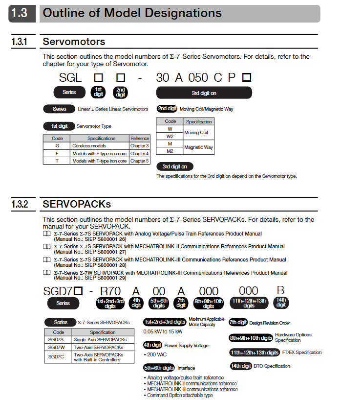
1. Product classification and model
Model system: The core is divided into three categories, corresponding to different iron core structures and application scenarios:
Model Series Structure Type Core Features Applicable Scenarios
SGLG ironless, low inertia, silent operation, precise positioning, high-speed reciprocating motion
SGLF F-type iron core with high thrust density, supporting self cooling/water-cooled medium and heavy-duty automation equipment
SGLT T-shaped iron core vigorously promotes heavy-duty machine tools and large-scale production lines
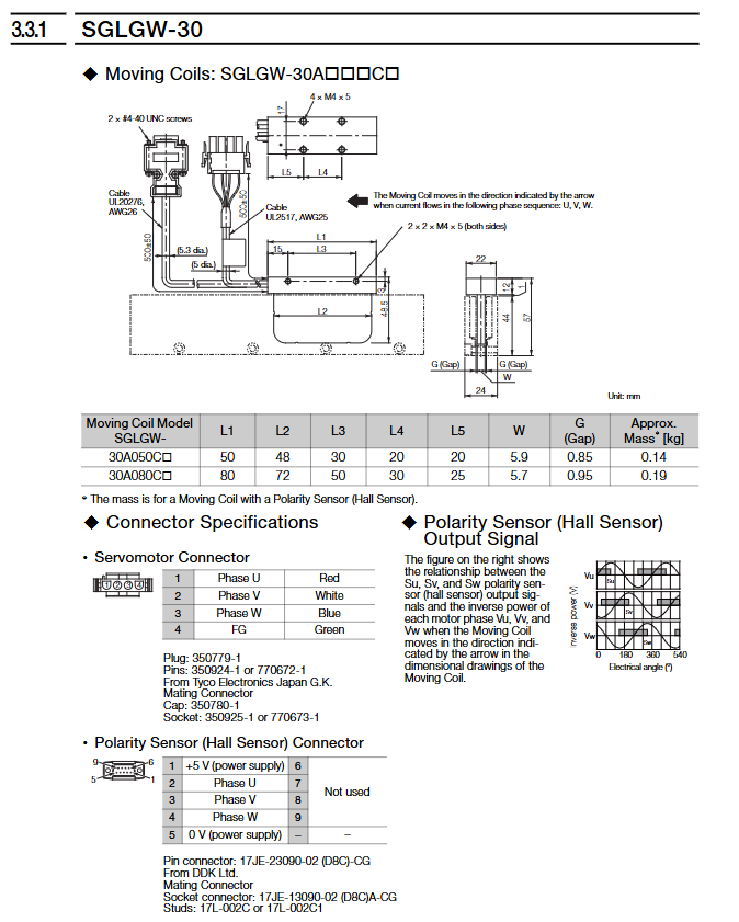
Model interpretation: Taking SGLFW2-30A070AS1 as an example, "SGL" is the ∑ -7 series identifier, "F" is the F-type iron core, "W2" is the rotor, "30" is the magnet height of 30mm, "A" is powered by 200V, "070" is the rotor length of 70mm, "AS" is with polarity sensor and thermal protector, and "1" is the self cooling method.
2. Core performance parameters
Power supply voltage: uniformly 200VAC (single-phase/three-phase), insulation level B, withstand voltage 1500VAC/1 minute
Thrust range: rated thrust 0.1-2520N, instantaneous maximum thrust 30-7560N
Speed range: rated speed 0.5-5m/s, maximum speed 1.5-7.5m/s
Environmental requirements: working temperature 0-40 ℃, humidity 20% -80% RH (non condensing), altitude ≤ 1000m
Selection calculation
1. Core formula for selection
Steady state thrust:F L=9.8×M×(m W+m T+m M)+F(m Acceleration thrust:F P=(m W+m T+m M)× t onev+F L (v is speed, t ₐ is acceleration time)
Effective thrust:F RMS= tF Ptwo⋅t one+F L two⋅t C+F S two⋅t d(t is the cycle time)
2. Selection verification criteria
Acceleration thrust ≤ maximum thrust × 0.9
Effective thrust ≤ rated thrust × 0.9
Load quality ≤ maximum allowable load (to be combined with brake resistor configuration)
Installation specifications
1. Installation environment requirements
Environmental restrictions: Indoor use, no corrosive/explosive gases, no strong magnetic field interference
Mechanical conditions: vibration acceleration ≤ 49m/s ², impact acceleration ≤ 196m/s ² (twice)
Special protection: The magnetic track contains strong permanent magnets and should be kept away from electronic medical equipment such as pacemakers to avoid magnetic substances from approaching
2. Installation operation process
(1) Magnetic track installation
Positioning accuracy: magnetic track spacing tolerance ± 0.1mm, alignment with reference marks when connecting multiple magnetic tracks
Fixed requirement: Use grade 10.9 hex screws with a tightening torque of 3.6-41.5N · m (depending on the model)
Gap control: The gap between the magnetic track and the rotor is 0.8-1.4mm (0.5-1.2mm with magnetic cover)
(2) Assembly of moving parts
Installation steps: First fix the rotor to the workbench → slowly approach the magnetic track → confirm that there is no contact noise → calibrate the gap with a non-magnetic feeler gauge
Screw specification: M4-M8 grade screw, tightening torque 2.4-20N · m, fitting length ≥ 4mm
Cable handling: The moving sub cable needs to be fixed with a bending radius of ≥ 15mm (when the cable diameter is less than 8mm)
3. Special requirements for water-cooled models (SGLFW2-90A series)
Cooling medium: Deionized water, pH6.8-8.0, Conductivity ≤ 30mS/m
Flow pressure: rated flow 4L/min, maximum pressure 0.5MPa, water temperature 5-25 ℃
Protective measures: The pipeline needs to be made of stainless steel material and equipped with a filter (to filter impurities ≥ 0.5mm)
Connection configuration
1. Linear encoder connection
Compatible brands: Supports mainstream brands such as Heidenhain, Renishaw, Mitutoyo, etc
Installation conditions: The distance between the magnetic track and the magnetic track should be ≥ 10-40mm (depending on the motor model) to avoid magnetic leakage interference
Adjustment requirements: The exposed encoder needs to calibrate the position of the scanning head, and the sealed encoder needs to meet the installation tolerance
2. Wiring of servo amplifier
Wiring process: Main circuit cable → Encoder cable → Sensor cable (polarity sensor/thermal protector)
Cable selection:
Recommended models for cable type length restrictions
Servo main circuit cable ≤ 20 meters JZSP-CLN11/21/39 series
Encoder cable ≤ 50 meters JZSP-CLL00/30 series
Sensor cable ≤ 15 meters JZSP-CLL10/CL2L100 series
Grounding requirements: The grounding resistance of the servo amplifier should be ≤ 10 Ω (400V level)/≤ 100 Ω (200V level), and the shielding layer should be grounded at one end
3. Serial Conversion Unit (JZDP Series)
Function: Convert encoder signal to servo amplifier, support polarity sensor and thermal protector signal transmission
Key parameters: Power supply+5V ± 5%, current consumption ≤ 160mA, operating temperature 0-55 ℃
Maintenance and disposal
1. Regular inspection
Daily inspection: Check for vibration, abnormal noise, and cable wear daily to confirm that screws are not loose
Regular inspection: calibrate the gap between the magnetic track and the rotor annually, measure the insulation resistance (≥ 10M Ω/500VDC)
Overhaul cycle: Contact the manufacturer for comprehensive maintenance every 5 years, and do not disassemble on your own
2. Key points for troubleshooting
Common problems: Abnormal encoder signal (check installation spacing), overload alarm (verify effective thrust), cable breakage (check bending radius)
Insulation testing: Measure after disconnecting the servo amplifier, and do not perform voltage withstand testing on the sensor
3. Scrap disposal
Demagnetization requirement: The magnetic track needs to be heated to above 300 ℃ and maintained for 1 hour to eliminate magnetism
Environmental requirements: Follow the WEEE directive and classify the disposal of electronic components and metal casings
Safety and Compliance
1. Core security standards
Strong magnetic protection: The magnetic track has an adsorption force of up to 21500N, and non-magnetic tools should be used during operation to avoid finger squeezing
Power off operation: Disconnect the power before maintenance and wait for the servo amplifier CHARGE indicator light to turn off (≥ 5 minutes)
Static protection: Release static electricity before touching the connector, and do not directly touch the encoder pins with your hands
2. Compliance standards
North America: UL 1004-1, UL 1004-6, CSA C22.2 No.100
EU: CE certification (EMC 2014/30/EU, LVD 2014/35/EU), EN 61800-3
China: RoHS compliance, restricting harmful substances such as lead and mercury
- YOKOGAWA
- Reliance
- ADVANCED
- SEW
- ProSoft
- WATLOW
- Kongsberg
- FANUC
- VSD
- DCS
- PLC
- man-machine
- Covid-19
- Energy and Gender
- Energy Access
- Renewable Integration
- Energy Subsidies
- Energy and Water
- Net zero emission
- Energy Security
- Critical Minerals
- A-B
- petroleum
- Mine scale
- Sewage treatment
- cement
- architecture
- Industrial information
- New energy
- Automobile market
- electricity
- Construction site
- HIMA
- ABB
- Rockwell
- Schneider Modicon
- Siemens
- xYCOM
- Yaskawa
- Woodward
- BOSCH Rexroth
- MOOG
- General Electric
- American NI
- Rolls-Royce
- CTI
- Honeywell
- EMERSON
- MAN
- GE
- TRICONEX
- Control Wave
- ALSTOM
- AMAT
- STUDER
- KONGSBERG
- MOTOROLA
- DANAHER MOTION
- Bentley
- Galil
- EATON
- MOLEX
- Triconex
- DEIF
- B&W
- ZYGO
- Aerotech
- DANFOSS
- KOLLMORGEN
- Beijer
- Endress+Hauser
- schneider
- Foxboro
- KB
- REXROTH
- YAMAHA
- Johnson
- Westinghouse
- WAGO
- TOSHIBA
- TEKTRONIX
- BENDER
- BMCM
- SMC
- HITACHI
- HIRSCHMANN
- XP POWER
- Baldor
- Meggitt
- SHINKAWA
- Other Brands
- UniOP
- KUKA
- IBA
- Beckhoff
- ADLINK
-
Beckhoff CX1100-0910 - Power Supply Module
-
Beckhoff C5210-0010 - Communication Module C5210
-
BECKHOFF KL1352 - Bus Terminal SET OF 2 FREE FAST SHIP
-
Beckhoff EL3058 - 8 x analog input single ended 4...20mA 85惟 shunt 12bit
-
Beckoff CX1100-0920 - UPS Module 24VDC (US SELLER) * *
-
BECKHOFF C6920-0000 - C69200000 PLC Moudule
-
Beckhoff CX5120-0115 - CPU controller module CX5120-0115
-
Unknown 15F5C1E-Y50A - Of Frequency Converters
-
Beckhoff AX5118-0000-0200 - Servo Drive HTP0
-
BECKHOFF AX5106-0000-0200 - Servo Drive
-
Beckhoff CX5240-0175 - Module (free) #U2327D YG
-
Beckhoff CP6607-0001-0000 - Compact PC Panel Economy Installation Operator 5,7 "
-
Beckhoff EP3744-0041 - 2022 EP37440041 Module
-
Beckhoff CP6209-0001-0020 - 6.5" PC Touch Screen Control Panel 24VDC
-
Beckhoff CX9020-0111 - /U900 +8x+2xEL3121+1x EL9410+3xEL1008+1x EL2008 Set
-
Beckhoff C6525-1030-0050 - Industrial PC
-
Beckoff CX1100-0920 - UPS Module 24VDC (US SELLER)
-
Beckhoff CX5010-0120 - CX5010 Processor Intel Atom Z510 B24
-
Siemens 6FC5203-0AF04-1BA1 - Operation Panel
-
Beckhoff CX5230-0175 - / 000029724 Embedded PC / Industrial PC on Rail
-
Beckhoff CP3916-0000 - industrielles Anzeige- und Bedienterminal
-
BECKHOFF CX1500-M310 - CX1000-N000 CX1000-0011 CX1000-C00L CX1100-0002 PLC Module
-
Beckhoff EL1872 - 16-channel digital input terminal
-
BECKHOFF EP2318-0001 - module
-
Beckhoff CX9020-0110 - Basic CPU Module
-
Beckhoff EL2564 - EtherCAT Terminal, 4-channel LED output, 5鈥?8VDC, 4A, RGBW
-
Beckhoff CX5130-0155 - /000105637 Automation Embedded PC
-
B&R 400 - Power Control Panel Rev D0 24 VDC
-
Beckhoff CX2020-0155 - module
-
Beckhoff CX9020-0115 - PLC Module
-
BECKHOFF EL6695 - PLC EL 6695
-
BECKHOFF EL7047 - PLC Modules
-
Beckhoff CX1000-0012 - Control HW 2.2 + CX1500-M310 + CX1000-C00L + CX1100-0002+
-
Beckhoff C6920-1039-0030 - control cabinet industrial PC CPU Celeron 1.90 GHz, 2 cores
-
BECKHOFF CX1100-0910 - PLC Module#
-
Beckhoff IL2301-B318-0000 - Coupler Box 4 Channel Digital Input |
-
Beckhoff CX7080 - Module
-
Beckhoff C6930-0060 - Industrial PC
-
Beckhoff CP7902-1060-0000 - Touchscreen 15 " CP7902
-
beckhoff CX9020-0111 - Controller module or UPS
-
Beckhoff CX8091 - PLC Module CX8091
-
Beckhoff C6640-1008-0030 - Control Cabinet Industrial PC
-
BECKHOFF CX1100-0920 - module
-
Beckhoff C9900-M921 - see pictures
-
BECKHOFF CP6829-0001-0000 - Touch Panel
-
BECKHOFF C6930-0060 - Industrial Computer
-
BECKHOFF CX8050 - PLC module
-
Beckhoff CP6202-0021-0020 - Touch Screen #
-
BECKHOFF AM3031-0C20-0000 - SERVO MOTOR
-
Unknown BCH1302N11A1C - Servo motor
-
Beckhoff EL2502 - 2-channel pulse width output terminal
-
Beckhoff EL6731 - Profibus Master / *Rev: 0025
-
Beckhoff CP3918-0010 - Control Panel
-
BECKHOFF CP2915-0010 - [24 MONTH WARRANTY] Control Panel
-
Beckhoff AX5203-0000-0202 - Servo Drive
-
Schneider TSXDSY64T2K - PLC OUTPUT MODULE
-
Beckhoff EP4174-0002 - Module-
-
Beckhoff IL2302-B318-0000 - Profibus Box
-
Beckhoff CP6709-0001-0000 - Touchpanel
-
BECKHOFF CX2030-0123 - Controller
-
Beckhoff CX9020-0111 - Processor Module
-
Beckhoff CX1020-0000 - CX Basic CPU Module
-
Beckhoff AX2003-AS - Servo Drive HTP0
-
Beckhoff C6240-1052-0040 - 4-086-06-3073 Industrial Computer CB1052-0003
-
Beckhoff EL1918 - 8 xTwinSAFE Input
-
Beckhoff AM8072-0R20-0000 - Servomotor
-
BECKHOFF AM8021-1B21-0000 - servo motor #T882 YS
-
Beckhoff EL6224 - 4 X Terminal IO-LINK
-
Beckhoff CX5140-0135 - embedded PC with Intel Atom processor 4 GB HW 3.6
-
Beckhoff CP7201-1000-0000 - Panel PC #
-
Beckhoff CX5130-0121 - Embedded-PC 4GB CPU Module HW 2.5 Industrial PC
-
Beckhoff AM8022-0D41-1002 - Servomotor
-
BECKHOFF CX2030-0130 - Module
-
BECKHOFF EL1872 - 16-channel digital input terminal
-
Unknown GXMMW.A203P33 - 1pc encoder
-
Beckhoff EL6631-0000 - EtherCAT Terminal 2-Port EL 6631
-
BECKHOFF C6925-0030 - Industrial Computer
-
Beckhoff CX8190 - A Module
-
BECKHOFF CX2040-0135 - CX2040-0135/000000927 CPU BASE MODULE i7 2715QE 2.1GHz --
-
BECKHOFF KL6023-0000 - Wireless adapter
-
Saia Burgess PCD7.F700 - PCD7F700 Communication Module
-
Beckhoff CX5130-0112 - CPU Module
-
BECKHOFF CX1020-N010 - CX1020-N000 CX1020-0111 CX1100-0004 EL2008 EL3064 EL4004
-
Beckhoff EP1819-0021 - A Module
-
Beckhoff CX2030-0120 - / 4gb with CX2100 0004
-
B&R X20-XC-0292 - Automation Powerlink Ethernet Bus Controller Module
-
Beckhoff BK3110 - One PLC Module
-
BECKHOFF KL3222 - PLC Module
-
BECKHOFF CX1500-M310 - CX1000-N000 CX1000-0011 CX1000-C00L CX1100-0002 PLC MODULE
-
Beckhoff CP3918-0010 - Control Panel
-
Beckhoff CX2030-0100-1002 - /4GB + CX2100 + CX2550 + CX2500-0060 + SSD
-
Beckhoff EP1816-0008 - PLC Module
-
Beckhoff CX5130-0112 - Module
-
Beckhoff Cx1500-m750 - CPU Hw: 1.4
-
BECKHOFF AX5112-0000-0200 - AX511200000200 Servo Driver
-
Beckhoff EL3751 - EtherCAT Terminal 1 Channel Analog Input Multifunction 24 Bit
-
Beckhoff CX1100-0002 - Power Supply Module
-
Beckhoff CP3916-1016-0010 - Control Panel
-
BECKHOFF CX9001-1101 - #NAME?
-
Beckhoff EP3174-0002 - EtherCAT Box Module
-
Beckhoff C6030-0070 - servo drive
-
Beckhoff CX2020-0120 - /4GB CPU, CX2100-0904, 3x EL6900, EL1904, 16GB Memory
-
BECKHOFF C6110 - BOX-PC 113608
-
BECKHOFF EK1914 - module #P
-
Beckhoff C6140 - Ipox IP-4GVI63 + CH7009A_DVI_TV + SIEMENS A5E00369843 + WD800AAJB
-
Beckhoff CX5020-0111 - controller Good quality
-
BECKHOFF C6015-0010 - / 6559380 ULTRA-COMPACT INDUSTRIAL PC ()
-
Beckhoff AX5203-0000-0200 - PLC module
-
Beckhoff EL2872 - 16-channel digital output terminal
-
BECKHOFF C3640-0000 - Panel Industrial PC 100/240VAC 128MB E0122L
-
Beckhoff CX8031 - Module
-
Beckhoff CX5020-0120-1002 - PLC module#
-
Beckhoff C6140 - M845B + SIEMENS A5E00369843 + C9900_A159_1 + AUTOMATA CAN PCI 1N
-
BECKHOFF AX5112-0000-0200 - Servo Drive*ie
-
B&R ECPA42-01 - Analog Output Module 4-Channel, +/- 10V Output Signal, 20mA Max
-
Beckhoff EL6631-0010 - PLC Module
-
BECKHOFF C6930-0070 - CONTROL CABINET INDUSTRIAL PC
-
BECKHOFF AX5112-0000-0200 - AX511200000200 Servo Driver
-
BECKHOFF EK9000 - Programmable Logic Controller Module EK9000 EK9000
-
BECKHOFF C6920-1028-0000 - Industrial computer
-
Beckhoff CX2030-0120 - controller Module
-
Beckhoff BX8000-0000 - Bus Terminal Controller HW 4.4
-
B&R 3NC154.60-2 - Positioning Module#
-
BECKHOFF CX1020-0122 - PLC module
-
Beckhoff AM3032-0D40-0000 - Servo Motor
-
BECKHOFF CX5020-0111 - CPU Module CX5020-0111
-
Beckhoff CB1051 - G5 Motherboard
-
BECKHOFF KL2641 - 1-channel relay output terminal

K-JIANG

Add: Jimei North Road, Jimei District, Xiamen, Fujian, China
Tell:+86-15305925923