
K-WANG


SIEMENS SIMATIC S7-300 Beginner's Guide
SIEMENS SIMATIC S7-300 Beginner's Guide
The Siemens SIMATIC S7-300 Beginner's Guide (version 04/2007) takes conveyor belt motor control as an example and provides a detailed introduction to the entry-level operation of adapting CPU 312C (order number 6ES7312-5BE03-0AB0). The core process includes preparing a PC (installing STEP 7 Lite V3.0+SP2 and PC Adapter USB driver), installing wiring hardware components, configuring control in STEP 7 Lite, downloading programs, and executing test runs. The entire process must comply with electrical safety regulations and support motor start, direction switching, and stop functions. The overall operation time is about 1 hour, suitable for users with Windows operation and electrical basic knowledge.
Basic information of the document
Core positioning: A beginner's guide to S7-300 for beginners, explaining the complete process of PLC from hardware installation to program operation through an example of conveyor motor control
Key adaptation: Only applicable to CPU 312C (order number 6ES7312-5BE03-0AB0), requires SIMATIC Micro Memory Card (MMC), starting firmware version V2.6
Safety reminder: Clearly distinguish the four levels of "danger/warning/caution/attention" safety, emphasize that only qualified professionals are allowed to operate, and comply with safety standards such as IEC 204
Preparation in advance
Skill Requirements
Proficient in operating Microsoft Windows operating system
Master the basic knowledge of electronic and electrical engineering
List of Materials and Tools (Core Components)
|Category | Project | Order Number (Siemens) | Quantity | Remarks|
|Core module | CPU 312C | 6ES7312-5BE03-0AB0 | 1 | Integrated DI10/DO6, requires MMC card|
|Power Supply | Power Module | 6ES7307-1EA00-0AA0 | 1 | Provides DC 24V power supply|
|Installation accessories | Installation track | 6ES7390-1AB60-0AA0 | 1 | M6 screw is required to fix the grounding|
|Connection accessories | PC Adapter USB | 6ES7972-0CB20-0XA0 | 1 | MPI interface with driver program for connecting PC and CPU|
|Front connector | Screw type multi terminal front connector | 6ES7392-1AM00-0AA0 | 1 | Compatible with CPU wiring|
|Control element | Instantaneous contact switch | - | 4 | 24V/2A, used for motor start stop and commutation|
|Software | STEP 7 Lite | - | 1 | V3.0+SP2, available for free download|
|Tools | Screwdrivers, wire strippers, crimping tools, etc. | - | Several | Market procurement, including 3.5mm/4.5mm blade screwdrivers|
|Cable | Grounding cable (10mm ²), flexible cable (1mm ²), etc. | - | As needed | Grounding cable needs to be compatible with M6 screws|
Core operational process (step-by-step)
1. Prepare PC (software and interface settings)
Install STEP 7 Lite: from the official website( http://support.automation.siemens.com )Download and follow the wizard to complete the installation
Install PC Adapter USB driver: Insert the driver CD and follow the prompts to install
Set PG/PC interface: Select "PC Adapter (MPI)", configure USB connection, enable MPI communication between PC and CPU
2. Hardware installation and wiring
Installation track: fixed with 2 M6 screws, grounding cable cross-sectional area ≥ 10mm ², leaving a gap of ≥ 40mm above and below the track (for heat dissipation and operation)
Installation module: First install the power module (fixed by hand), then install the CPU 312C, and insert the front connector (not locked temporarily, convenient for wiring)
Wiring operation:
Prepare the cable: Cut it to the desired length, strip off the insulation layer, and put on a 6mm insulation ring
Wiring sequence: power supply → CPU 312C → momentary contact switch (connected to DI terminal) → motor (connected to DO terminal, optional)
Key requirement: Cut off the power before wiring, and set the line voltage selector correctly
Hardware debugging:
Connecting PC and CPU: Connect PC Adapter and PC with USB cable
Power on test: Insert the MMC card, set the CPU to STOP mode, and turn on the power (power DC24V LED lights up, CPU DC5V and STOP LED lights up)
Test wiring: Press the momentary contact switch and observe whether the corresponding CPU input LED lights up (such as the input 0.0 terminal LED corresponding to the start switch)
3. Software Configuration (STEP 7 Lite)
Open project: Start STEP 7 Lite and open the instance project "converyor.k7p"
Create module configuration:
New S7-300 station, automatically generate 4 installation tracks
Insert the power module (such as 6ES7307-1BA00-0AA0) and CPU 312C, and it will automatically display in the hardware view and configuration table
Set CPU parameters: Set the reserved bit storage quantity to "0" to avoid motor runaway startup after power failure
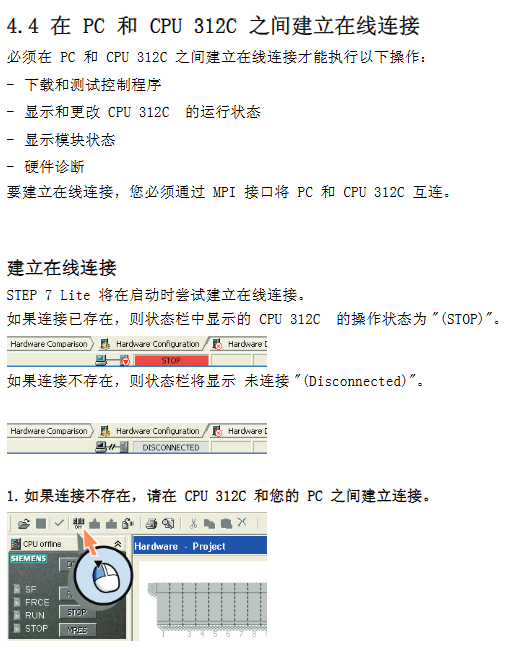
Establish online connection: When STEP 7 Lite starts, it automatically attempts to connect and the status bar displays "STOP" (connection successful) or "Disconnected" (manual connection required)
Download configuration: First, perform a CPU memory reset (delete old programs/configurations), then download a new configuration and check the consistency of offline/online configurations
4. Program operation and test run
Open program: The program in the project is stored in OB1 (Organizational Block 1), written using ladder logic (LAD), and includes 4 network segments (clockwise/counterclockwise/start/stop)
Download project: Download hardware configuration and OB1 program to CPU 312C, confirm to overwrite existing configuration/program
Test Run:
Switch CPU mode: Set the mode switch to "RUN", and the RUN LED will change from flashing to constantly on
Functional testing:
Start: Press the green momentary contact switch, input 0.0 LED briefly on, output 0.3 LED constantly on (motor ready)
Clockwise rotation: Press and hold the corresponding switch, input 0.2 LED lights up, output 0.0 LED lights up
Counter clockwise rotation: Press and hold the corresponding switch, input 0.3 LED lights up, output 0.5 LED lights up
Stop: Press the red momentary contact switch, input 0.1 LED briefly on, output 0.3 LED off
- YOKOGAWA
- Reliance
- ADVANCED
- SEW
- ProSoft
- WATLOW
- Kongsberg
- FANUC
- VSD
- DCS
- PLC
- man-machine
- Covid-19
- Energy and Gender
- Energy Access
- Renewable Integration
- Energy Subsidies
- Energy and Water
- Net zero emission
- Energy Security
- Critical Minerals
- A-B
- petroleum
- Mine scale
- Sewage treatment
- cement
- architecture
- Industrial information
- New energy
- Automobile market
- electricity
- Construction site
- HIMA
- ABB
- Rockwell
- Schneider Modicon
- Siemens
- xYCOM
- Yaskawa
- Woodward
- BOSCH Rexroth
- MOOG
- General Electric
- American NI
- Rolls-Royce
- CTI
- Honeywell
- EMERSON
- MAN
- GE
- TRICONEX
- Control Wave
- ALSTOM
- AMAT
- STUDER
- KONGSBERG
- MOTOROLA
- DANAHER MOTION
- Bentley
- Galil
- EATON
- MOLEX
- Triconex
- DEIF
- B&W
- ZYGO
- Aerotech
- DANFOSS
- KOLLMORGEN
- Beijer
- Endress+Hauser
- schneider
- Foxboro
- KB
- REXROTH
- YAMAHA
- Johnson
- Westinghouse
- WAGO
- TOSHIBA
- TEKTRONIX
- BENDER
- BMCM
- SMC
- HITACHI
- HIRSCHMANN
- XP POWER
- Baldor
- Meggitt
- SHINKAWA
- Other Brands
- UniOP
- KUKA
- IBA
- Beckhoff
-
LTI SC52.0040.0012.0000.0 - Servo Drive
-
Lti SC52.0040.0012.0000.0 - Servo Drive
-
Milton Industries LTI Tool By Milton LT1240 - 1/2" Drive Lugnut Remover
-
LTi Drives SO84.200.P030.0000.0-W - Servo Spindle Drive
-
LTI DRIVES LSP08-035-320-30-B0R1PY170 - Servo Motor
-
LTI DRIVES SE84.200.SC00.0001.0-W - Servo Drive
-
Lust CDE34.005.W2.2 - Lti Drives Controller
-
LTi SO84.012.0030.0011.2 - ServoOne Servo Drive
-
LTi Drives SO CM-P.0010.11.00.0 - Servo Drive Controller
-
LTi CDE34.017.W3.0 - Servo Drive
-
LTI Drives CDB32.004, C2.0,SH - Positioning Controller
-
LUST CM-CAN1 - LTi DRIVES Communication Module
-
LTi SO84.012.1030.0000.2 - Servo Drive
-
LTI MOOG CDE54.044 - PITCHMASTER FREQUENCY CONVERTER 181-01019
-
MOOG LTI 181-01019 CDE54.044 - PITCHMASTER FREQUENCY CONVERTER
-
Lust LTi Drives CDE34.010,D2.0 - Servo Drive Controller
-
LTI SO84.032.0003.0101.2 - Servo Drive
-
Seagate 9CC132-302 Harris LTI-CS IRT-34-0021-01 - Hard Drive 160GB
-
LTI SO84.032.0003.0001.2 - Servo Drive
-
LTI SO24.007.0070.0000.1 - SERVO CONTROLLER
-
LTi drive CDA32.003.C3.0.H05-01.PC1 - Servo Drive
-
LTI SO84.016.0030.0000.2 - SERVO CONTROLLER
-
LUST LTI CD A34.008,W1.4, BR - SERVO DRIVE
-
MOOG LTI 181-01019 CDE54.044 - PITCHMASTER FREQUENCY CONVERTER
-
LTI MOOG 181-01019 - PITCH Master Servo Drive CDE54.044
-
LTI SERVO ONE SO84.045.0030.0001.2-W - Drive
-
LUST LTi SO84.032.0040.0000.2 - SERVO ONE DRIVE
-
LTi Drives LSH-074-2-30-3 20/T1,G6.1M - SERVO MOTOR
-
LTI SO84.016.0000.0101.2 - servo drive
-
LTI SA54.0550.0033.0000.0 - Servo Drive
-
LTI SA54.0550.0033.0000.0 - Servo Drive
-
LTI LT 4850 - 3/8" Drive 3-Pc Twist Socket Transmission Drain Plug Removal System
-
LTI Tools LT4400-30 Lock Technology - 3/4" Twist Socket 1/2" Drive Lugnut Remover
-
LTI Tools LT-1400C - 1/2 Drive Wheel Torque Extension Tool
-
LTI Tools LT1250 - 1/2" Drive Dual Sided Socket Lug Nut Remover Tool
-
LTI SO84.032.0003.0101.2 - Servo Drive
-
LTI MOOG 181-01019 - PITCH Master Servo Drive CDE54.044
-
MOOG LTI 181-01019 CDE54.044 - PITCHMASTER FREQUENCY CONVERTER
-
MOOG LTI 181-01019 CDE54.044 - PITCHMASTER FREQUENCY CONVERTER
-
MOOG LTI 181-01019 CDE54.044 - PITCHMASTER FREQUENCY CONVERTER
-
LTI SA54.0550.0033.0000.0 - Servo Drive
-
LTI Tools LT-4800 - 7 Piece Twist Socket 3/8" Drive Oil Drain Plug Removal Set
-
LTI SA54.0550.0033.0000.0 - Servo Drive
-
LTI Drive SO24.007.00300000.0 - Servo Drive
-
LTI TOOLS LTI 1400-I - Drive Wheel Torque Extension
-
LTI Tools LT4400-3 - 3/4" 19mm Twist Socket 1/2" Drive Lugnut
-
LTI TOOLS LTI 1400-BB - Drive Wheel Torque Extension
-
LTI SO84.032.0003.0101.2 - Servo Drive
-
LTI Tools LT-4512 - 3/8" Drive 12mm Twist Socket
-
LTI MOTION Luster SO84.032.0003.0001.2 - Servo Drive
-
LTI Tool By Milton LT1600P - 1" Drive Torx Stick
-
LTI Lust VF1424L,HF,OP2,S56 - Variable Frequency Drive
-
LUST CDA32.004,C1.4,H08,B0 - SERVO DFRIVE CM-CAN1 Module
-
LTI SO84.045.0002.0001.2-W - Drive
-
LTI Lust VF1404M,C9,PT1,BR1 - Inverter Type VF1404M
-
LTI SA54.0550.0033.0000.0 - Servo Drive
-
LTI Tools LT-1400C - 1/2" Drive Wheel Torque Extension
-
Lust LTI DRiVES CDA32.006, C3.0, H09 - Variateur De Fr茅quence Frequency Inverter
-
LTI MOOG CDE54.044 - PITCH master SERVO DRIVE
-
LTI MOOG CDE54.044 - PITCH master SERVO DRIVE
-
LTI SO84.143.0020.0101.2-W - servo drive
-
LTI MOTION SC34.0200.0011.0000.0 - Servo drives
-
LTI SO84.032.0003.0001.2 - Servo Drive
-
LTI DRIVES GmbH MS100 - Assembly Set Mounting Kit
-
LTI SO84.032.0003.0001.2 - Servo Drive
-
LTI SO84.032.0003.0001.2 - Servo Drive
-
LTI MOTION SO84.032.0003.0101.2 - servo drive
-
LTI SO84.032.0003.0101.2 - Servo Drive
-
LTI MOOG CDE54.044 - PITCH master SERVO DRIVE
-
LTI MOTION CDE32.004.C2.4 - Servo drives
-
LTI CDD34.032锛學x.x锛孊R锛孭C1 - Servo Drive
-
Lust LTI DRiVES CDA32.006, C3.0, H09 - Inversor De Frecuencia Frequency Inverter
-
Lust SO84.008.0030.1000.0 - Servo One LTi Drive
-
LTI MOTION SO84.032.0003.0101.2 - Servo drives
-
LUST LTi CDA32.004,C1.4 - SERVO DRIVE
-
LTI MOOG CDE54.044 - PITCH Master SERVO DRIVE
-
LTI KEBA CDB32.004 C2.7, SH - PN: 08673530 Frequency Inverter
-
LTI Tools LT-1400C - 1/2" Drive Wheel Torque Extension
-
LTI LT1400-E - 1/2" Drive Wheel Torque Extension
-
LTI MOOG 181-01019 - PITCH master SERVO DRIVE CDE54.044
-
LTI LSN-097-0510-30-560/T1 - Actuator Motor
-
LTI Tools LT 4800 - 7 Piece 3/8" Drive Twist Socket Oil Drain Plug Removal System
-
LTI DRIVES GmbH MS100 - MONTAGESET Assembly Set Mounting Kit
-
Lti SC52.0040.0012.0000.0 - Servo Drive
-
LTI DRIVES GmbH MS100 - Juego De Montaje Assembly Set Mounting Kit
-
LTi DSM4-14.2-21R83-200 - Drives servomoteur Servo Motor
-
MOOG CDE 54.044.GDA - Pitch Master Industrielle Turbine Lti Drive
-
LTI SO24.004.0030.1000.0 - Servo Drive Controller
-
Lti MOOG CDE54.044 - Pitch Master Servo Drive
-
Lust LTI DRiVES CDA32.006, C3.0, H09 - Inverter
-
LTI MOTION GMBH CDB34.006,W3.0,PC1,H39 - Frequency inverter
-
LTI SO84.032.0003.0001.2 - Servo Drive
-
MOOG CDE 54.044.D - Pitch Master Industrielle Turbine Lti Drive
-
LTI TOOLS LT-1460 - 1/2" DRIVE WHEEL TORQUE EXTENSION KIT 5 PIECE SET
-
Lust Cdb32.003, C2.4 - Lti Drives Servoregulador Frecuencia Servo Controller Inverter
-
Lust LTI DRIVES CDA32.006, C3.0, H09 - Frequency Inverter
-
Lust Lti SO82.004.0030.0000.2 - Servo Drive
-
LTI MOTION SC34.0200.0011.0000.0-SL - Servo drives
-
LTI MOTION SA54.0075.0033.0000.0 - Servo drives
-
LTI MOTION SC32.0075.1011.0000.0 - Servo drives
-
LTI Servo-One Junior SO22.006.0080.1000.0 - Servo Controller Servoregler
-
LUST CDA32.004, C1.4, H08, B0 - Servo Drive & LTI CM-CAN1 Module
-
LTI DRIVES LSP08-035-320-30-B0R1PY170 - Servo Motor
-
LUST LTI CDA32.004,C1.4.H08.B0 - SERVO CONTROLLER DRIVES
-
LUST LTi DRiVES CDS44.072LC1.2 - Servo Drive
-
Lti Servo-One Junior SO22.006.0082.1000.0 - Servo Controller Servoregler
-
LUST CDA32.008,C2.0,HF - Lti DRIVES Spindle Drive Inverter
-
LTI SO22.003.0082.0000.0 - Servo Drives One junior Servo Controller Servoregler
-
Lust Lti Drives CM-CAN1 - Communication Module
-
LUST Lti Drives Vf1202s, G8, I6 - Frequency Inverter Drive
-
LTI DRIVES BR-090.03.540.UR.H38 - Bremswiderstand Brake Resistor
-
LTi DRIVES PM-E40.2DRA054P - Wind Turbine Pitch Control Inverter
-
LTi Drives GmbH br-110.01.540-UR - Brake Resistor
-
LTI Drives LSN-097-0960-30-0560/T1,S4,B - Servo Motor
-
LUST CDA34.006.C2.0 - LTI Drives Servoregler
-
LUST LTI DRIVES SERVO ONE JUNIOR SO24.002.0020.0000.1 - Servo Drive Controller
-
LTI MOTION SO84.032.0003.0001.2 - Servo drives
-
LTI DDTD750V2-120 - IBOP ACTUATOR CYLINDER FOR TOP DRIVE
-
LTI CDE32.004, C2.4 - SERVO DRIVE
-
LUST LTI DRIVES CDD34.017 W3.4PC1 - Servo Drive Controller
-
LTI CDA3208,C3,0,HF - AC SERVO DRIVE
-
LUST LTI DRIVES LSH-074-3-30-560/T1,G6.1S - SERVO MOTOR
-
LUST Lti CDB32.004.C2.4.SH - AC Servo Drive
-
LTi CDA32.006, C3.0, H09 - Servo Drive
-
LTI SO22.003.0010.0000.0 - Servo Drive Servo one junior Servoregler Controller
-
LTi Drives DSM4-14.2-21R83-200 - Servo Motor
-
LUST Lti Drives Lsh-097-1-30-560/T1, 1R - Servomotor
-
LTI 1237 - 7 Piece 1/2" Drive Flip Socket Set

K-JIANG

Add: Jimei North Road, Jimei District, Xiamen, Fujian, China
Tell:+86-15305925923