
K-WANG


SIEMENS 1FK6 series three-phase servo motor
SIEMENS 1FK6 series three-phase servo motor
Product Core Definition and Positioning
Product type: Permanent magnet excitation three-phase synchronous servo motor, following the principle of sine current, suitable for motor controlled AC converter
Core advantages: Rare earth permanent magnet materials empower efficient driving, integrated encoder realizes speed and rotor position detection, supports indirect positioning function
Key parameter details:
Category specific parameter notes
Protection level IP64 (basic model) optional IP65/IP67, driver end flange optional IP67
Self cooling method (EN 60034-6) does not require additional cooling devices and is suitable for continuous operation scenarios
Acoustic characteristics below 3000rpm: 55-70dB (A) 1FK6 03./04. Approximately 55dB (A), 1FK6 10. Approximately 70dB (A)
Insulation Class F (EN 60034-1) is suitable for high temperature working environments and extends winding life
Bearing lifespan of 20000 hours (guide value) with permanent grease lubrication and maintenance free design
Environmental adaptation temperature -15 ℃~+40 ℃ Power coefficient 0.92 at 50 ℃, 0.82 at 60 ℃
Cylindrical end design without keyway (tolerance k6), optional version with keyway and guide key (tolerance k6)
Full process operation specifications (detailed explanation of core chapters)
1. Transportation and Storage (Chapter 4)
Transportation requirements:
Weight limit: The weight of a single motor can reach 50kg, and lifting equipment that complies with the 98/37/EU Machinery Directive must be used
Operation taboos: Do not collide with the shaft end and bearing to avoid permanent magnet rotor adsorbing ferromagnetic objects
Transportation protection: Use suspension straps or lifting rings provided by the manufacturer, following the transportation regulations of the destination country
Storage conditions:
Environmental requirements: Dry, low dust, low vibration (effective vibration v ₑ ff<0.2mm/s) indoor space
Protective measures: Keep the original packaging to prevent corrosion and avoid close contact with electronic data media and pacemaker wearers (strong magnetic interference)
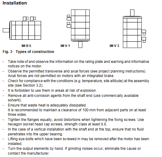
2. Installation and fixation (Chapter 4)
Preparation before installation:
Surface treatment: Thoroughly remove the anti-corrosion agent at the shaft end with commercial solvents to avoid affecting the transmission fit
Environmental verification: Confirm that the installation location temperature and altitude meet the requirements, and prohibit use in explosive hazardous areas
Installation operation:
Fixed specification: Use hexagon socket head screws with a strength grade of ≥ 8.8, tighten the flange evenly, and avoid deformation
Gap requirement: At least 100mm gap should be reserved between three sides of the motor and adjacent components to ensure heat dissipation and maintenance space
Special installation: When installing vertically (with the shaft end facing upwards), it is necessary to prevent liquid from seeping into the upper bearing; Motors with integrated brakes are prohibited from bearing axial forces
Balance requirement: The motor with keyway has been balanced with a semi guide key before leaving the factory. If transmission components are installed, they need to be re balanced as a whole according to ISO1940
3. Electrical Connections (Chapter 5)
Safety prerequisite:
Voltage risk: When the rotor rotates, the terminal voltage of the motor can reach 300V. Electrical work must be disconnected first, following the EN 50110-1 (DIN VDE 0105-100) standard
Static protection: Encoders and temperature sensors are static sensitive components, and touching the terminals with live hands/tools is prohibited
Wiring specifications:
Cable requirements: It is recommended to use Siemens prefabricated cables that are compatible with current and voltage. Both power and signal lines must be shielded (to prevent electromagnetic interference)
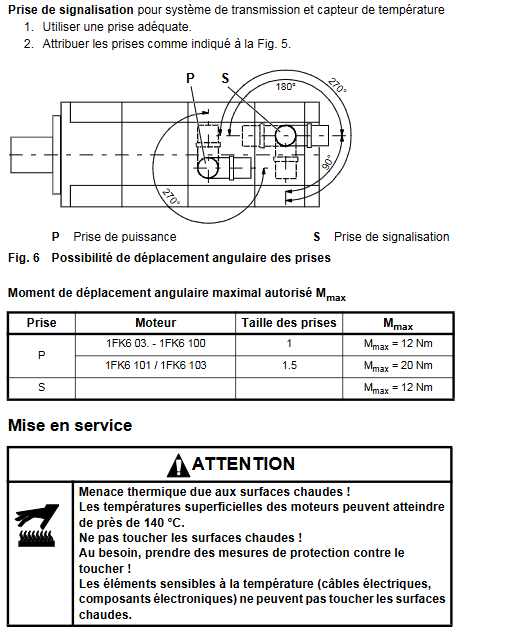
Plug operation:
Power plug: size 1 for 1FK6 03. -100 (torque ≤ 12Nm), size 1.5 for 1FK6 101/103 (≤ 20Nm)
Signal plug: compatible with encoder and temperature sensor, torque ≤ 12Nm
Operation taboos: The output direction of the plug can be adjusted up to 10 times, and excessive twisting is prohibited to cause cable damage
Brake wiring: Connected through a power plug, powered by 24V DC ± 10%, only used for emergency stop (cannot be used as a working brake)
Grounding requirement: PE conductor must be connected to ensure effective protection function
4. Startup and Debugging (Chapter 6)
Pre startup inspection:
Wiring verification: All plugs are securely fastened and not loose; The cable has no protruding wires, and the inside of the plug is clean and dry
Protection activation: All protective devices of the motor (temperature sensors, thermal overload relays, etc.) are in working condition
Mechanical inspection: The drive system is not stuck, the shaft end key (if any) is fixed to prevent swinging, and the tension of the transmission parts (such as belts) is adapted
Brake test: Apply 24V DC ± 10% to the BR and BR2 pins to confirm that the rotor rotates freely without any frictional noise
Start operation:
Unlock the brake (if necessary) and complete the system linkage according to the converter (such as SIMODRIVE) manual
Confirm that the maximum speed of the motor (n ₘₐₓ) does not exceed the nameplate markings to avoid operating at excessive speeds
Monitoring operation status: surface temperature not exceeding 140 ℃, no abnormal vibration or noise
System integration: Complete positioning, speed regulation and other functional debugging according to device requirements to ensure stable coordination with the converter
5. Maintenance and troubleshooting (Chapters 7-8)
Routine maintenance:
Cleaning requirements: Regularly clean the surface of the motor according to the degree of on-site pollution to ensure smooth heat dissipation
Wear life of vulnerable parts: about 5000 hours for radial shaft seals (oil lubrication) and 20000 hours for bearings (guidance value)
Special note: After disassembling the motor, the encoder system must be recalibrated before it can be used again
Common troubleshooting:
Core causes of fault phenomena and solutions
Insufficient shielding of irregular motor/encoder cables during operation; Check for shielding and grounding when the controller gain is too high; Adjust the controller according to the converter manual
Abnormal vibration transmission components/unbalanced load; Poor alignment of the drive chain; Loosening of fixing screws and rebalancing; Correction alignment; Check and tighten the screws
Foreign objects inside the motor with abnormal noise during operation; The manufacturer specializes in repairing damaged bearings and prohibits self disassembly
Motor overheating (surface temperature>140 ℃) and load overload; Heat dissipation obstruction (dust accumulation), load verification (refer to nameplate); Clean the surface and ensure the flow of cooling air
6. Disposal and scrapping (Chapter 8)
Scrap standard: Follow national and local environmental regulations, dispose of according to standard recycling procedures, or return to Siemens manufacturer
Special disposal: Encoder electronic components need to be treated separately as electronic waste to avoid environmental pollution
Data retention: Product nameplate data needs to be retained with the equipment for subsequent maintenance and traceability
Safety regulations and important tips
1. Core security risks and protection
Electrical risk: Before operation, power must be cut off, tested, and grounded to prevent electric shock from the 300V terminal voltage
Hot air hazard: The maximum temperature on the surface of the motor is 140 ℃. It is forbidden to touch high-temperature surfaces, and temperature sensitive components should be kept away from them
Mechanical risk: Protective devices need to be installed when the rotor rotates, and the shaft end key needs to be fixed to prevent it from being thrown out; Do not collide with the shaft end and bearing
Magnetic interference risk: The rotor contains strong magnetic permanent magnets, and pacemaker wearers need to stay away from the disassembled rotor; Electronic data media should be kept away from proximity
Installation taboos: It is prohibited to directly connect to the three-phase power grid (which may cause damage to the motor), and must be driven through the configured converter
2. Key standards and compliance requirements
Product compliance: Compliant with EN 60034 series standards, 73/23/EEC low voltage directive, standard motor with UL certification (nameplate marked UR)
Operating standards: comply with EN 50110-1 (Electrical Work Safety), ISO1940 (Balance Standards), etc
Responsibility statement: Only allowed to be used in conjunction with equipment recommended/approved by Siemens. Proper transportation and installation are prerequisites for safe operation
Supplementary explanation
Optional configuration:
Protection upgrade: IP65 protection level, driver end flange IP67
Performance Expansion: HD (High Dynamic) Low Inertia Series
Component options: planetary gearbox, incremental/absolute encoder, rotary transformer
- YOKOGAWA
- Reliance
- ADVANCED
- SEW
- ProSoft
- WATLOW
- Kongsberg
- FANUC
- VSD
- DCS
- PLC
- man-machine
- Covid-19
- Energy and Gender
- Energy Access
- Renewable Integration
- Energy Subsidies
- Energy and Water
- Net zero emission
- Energy Security
- Critical Minerals
- A-B
- petroleum
- Mine scale
- Sewage treatment
- cement
- architecture
- Industrial information
- New energy
- Automobile market
- electricity
- Construction site
- HIMA
- ABB
- Rockwell
- Schneider Modicon
- Siemens
- xYCOM
- Yaskawa
- Woodward
- BOSCH Rexroth
- MOOG
- General Electric
- American NI
- Rolls-Royce
- CTI
- Honeywell
- EMERSON
- MAN
- GE
- TRICONEX
- Control Wave
- ALSTOM
- AMAT
- STUDER
- KONGSBERG
- MOTOROLA
- DANAHER MOTION
- Bentley
- Galil
- EATON
- MOLEX
- Triconex
- DEIF
- B&W
- ZYGO
- Aerotech
- DANFOSS
- KOLLMORGEN
- Beijer
- Endress+Hauser
- schneider
- Foxboro
- KB
- REXROTH
- YAMAHA
- Johnson
- Westinghouse
- WAGO
- TOSHIBA
- TEKTRONIX
- BENDER
- BMCM
- SMC
- HITACHI
- HIRSCHMANN
- XP POWER
- Baldor
- Meggitt
- SHINKAWA
- Other Brands
- UniOP
- KUKA
- IBA
- Beckhoff
-
LTI SC52.0040.0012.0000.0 - Servo Drive
-
Lti SC52.0040.0012.0000.0 - Servo Drive
-
Milton Industries LTI Tool By Milton LT1240 - 1/2" Drive Lugnut Remover
-
LTi Drives SO84.200.P030.0000.0-W - Servo Spindle Drive
-
LTI DRIVES LSP08-035-320-30-B0R1PY170 - Servo Motor
-
LTI DRIVES SE84.200.SC00.0001.0-W - Servo Drive
-
Lust CDE34.005.W2.2 - Lti Drives Controller
-
LTi SO84.012.0030.0011.2 - ServoOne Servo Drive
-
LTi Drives SO CM-P.0010.11.00.0 - Servo Drive Controller
-
LTi CDE34.017.W3.0 - Servo Drive
-
LTI Drives CDB32.004, C2.0,SH - Positioning Controller
-
LUST CM-CAN1 - LTi DRIVES Communication Module
-
LTi SO84.012.1030.0000.2 - Servo Drive
-
LTI MOOG CDE54.044 - PITCHMASTER FREQUENCY CONVERTER 181-01019
-
MOOG LTI 181-01019 CDE54.044 - PITCHMASTER FREQUENCY CONVERTER
-
Lust LTi Drives CDE34.010,D2.0 - Servo Drive Controller
-
LTI SO84.032.0003.0101.2 - Servo Drive
-
Seagate 9CC132-302 Harris LTI-CS IRT-34-0021-01 - Hard Drive 160GB
-
LTI SO84.032.0003.0001.2 - Servo Drive
-
LTI SO24.007.0070.0000.1 - SERVO CONTROLLER
-
LTi drive CDA32.003.C3.0.H05-01.PC1 - Servo Drive
-
LTI SO84.016.0030.0000.2 - SERVO CONTROLLER
-
LUST LTI CD A34.008,W1.4, BR - SERVO DRIVE
-
MOOG LTI 181-01019 CDE54.044 - PITCHMASTER FREQUENCY CONVERTER
-
LTI MOOG 181-01019 - PITCH Master Servo Drive CDE54.044
-
LTI SERVO ONE SO84.045.0030.0001.2-W - Drive
-
LUST LTi SO84.032.0040.0000.2 - SERVO ONE DRIVE
-
LTi Drives LSH-074-2-30-3 20/T1,G6.1M - SERVO MOTOR
-
LTI SO84.016.0000.0101.2 - servo drive
-
LTI SA54.0550.0033.0000.0 - Servo Drive
-
LTI SA54.0550.0033.0000.0 - Servo Drive
-
LTI LT 4850 - 3/8" Drive 3-Pc Twist Socket Transmission Drain Plug Removal System
-
LTI Tools LT4400-30 Lock Technology - 3/4" Twist Socket 1/2" Drive Lugnut Remover
-
LTI Tools LT-1400C - 1/2 Drive Wheel Torque Extension Tool
-
LTI Tools LT1250 - 1/2" Drive Dual Sided Socket Lug Nut Remover Tool
-
LTI SO84.032.0003.0101.2 - Servo Drive
-
LTI MOOG 181-01019 - PITCH Master Servo Drive CDE54.044
-
MOOG LTI 181-01019 CDE54.044 - PITCHMASTER FREQUENCY CONVERTER
-
MOOG LTI 181-01019 CDE54.044 - PITCHMASTER FREQUENCY CONVERTER
-
MOOG LTI 181-01019 CDE54.044 - PITCHMASTER FREQUENCY CONVERTER
-
LTI SA54.0550.0033.0000.0 - Servo Drive
-
LTI Tools LT-4800 - 7 Piece Twist Socket 3/8" Drive Oil Drain Plug Removal Set
-
LTI SA54.0550.0033.0000.0 - Servo Drive
-
LTI Drive SO24.007.00300000.0 - Servo Drive
-
LTI TOOLS LTI 1400-I - Drive Wheel Torque Extension
-
LTI Tools LT4400-3 - 3/4" 19mm Twist Socket 1/2" Drive Lugnut
-
LTI TOOLS LTI 1400-BB - Drive Wheel Torque Extension
-
LTI SO84.032.0003.0101.2 - Servo Drive
-
LTI Tools LT-4512 - 3/8" Drive 12mm Twist Socket
-
LTI MOTION Luster SO84.032.0003.0001.2 - Servo Drive
-
LTI Tool By Milton LT1600P - 1" Drive Torx Stick
-
LTI Lust VF1424L,HF,OP2,S56 - Variable Frequency Drive
-
LUST CDA32.004,C1.4,H08,B0 - SERVO DFRIVE CM-CAN1 Module
-
LTI SO84.045.0002.0001.2-W - Drive
-
LTI Lust VF1404M,C9,PT1,BR1 - Inverter Type VF1404M
-
LTI SA54.0550.0033.0000.0 - Servo Drive
-
LTI Tools LT-1400C - 1/2" Drive Wheel Torque Extension
-
Lust LTI DRiVES CDA32.006, C3.0, H09 - Variateur De Fr茅quence Frequency Inverter
-
LTI MOOG CDE54.044 - PITCH master SERVO DRIVE
-
LTI MOOG CDE54.044 - PITCH master SERVO DRIVE
-
LTI SO84.143.0020.0101.2-W - servo drive
-
LTI MOTION SC34.0200.0011.0000.0 - Servo drives
-
LTI SO84.032.0003.0001.2 - Servo Drive
-
LTI DRIVES GmbH MS100 - Assembly Set Mounting Kit
-
LTI SO84.032.0003.0001.2 - Servo Drive
-
LTI SO84.032.0003.0001.2 - Servo Drive
-
LTI MOTION SO84.032.0003.0101.2 - servo drive
-
LTI SO84.032.0003.0101.2 - Servo Drive
-
LTI MOOG CDE54.044 - PITCH master SERVO DRIVE
-
LTI MOTION CDE32.004.C2.4 - Servo drives
-
LTI CDD34.032锛學x.x锛孊R锛孭C1 - Servo Drive
-
Lust LTI DRiVES CDA32.006, C3.0, H09 - Inversor De Frecuencia Frequency Inverter
-
Lust SO84.008.0030.1000.0 - Servo One LTi Drive
-
LTI MOTION SO84.032.0003.0101.2 - Servo drives
-
LUST LTi CDA32.004,C1.4 - SERVO DRIVE
-
LTI MOOG CDE54.044 - PITCH Master SERVO DRIVE
-
LTI KEBA CDB32.004 C2.7, SH - PN: 08673530 Frequency Inverter
-
LTI Tools LT-1400C - 1/2" Drive Wheel Torque Extension
-
LTI LT1400-E - 1/2" Drive Wheel Torque Extension
-
LTI MOOG 181-01019 - PITCH master SERVO DRIVE CDE54.044
-
LTI LSN-097-0510-30-560/T1 - Actuator Motor
-
LTI Tools LT 4800 - 7 Piece 3/8" Drive Twist Socket Oil Drain Plug Removal System
-
LTI DRIVES GmbH MS100 - MONTAGESET Assembly Set Mounting Kit
-
Lti SC52.0040.0012.0000.0 - Servo Drive
-
LTI DRIVES GmbH MS100 - Juego De Montaje Assembly Set Mounting Kit
-
LTi DSM4-14.2-21R83-200 - Drives servomoteur Servo Motor
-
MOOG CDE 54.044.GDA - Pitch Master Industrielle Turbine Lti Drive
-
LTI SO24.004.0030.1000.0 - Servo Drive Controller
-
Lti MOOG CDE54.044 - Pitch Master Servo Drive
-
Lust LTI DRiVES CDA32.006, C3.0, H09 - Inverter
-
LTI MOTION GMBH CDB34.006,W3.0,PC1,H39 - Frequency inverter
-
LTI SO84.032.0003.0001.2 - Servo Drive
-
MOOG CDE 54.044.D - Pitch Master Industrielle Turbine Lti Drive
-
LTI TOOLS LT-1460 - 1/2" DRIVE WHEEL TORQUE EXTENSION KIT 5 PIECE SET
-
Lust Cdb32.003, C2.4 - Lti Drives Servoregulador Frecuencia Servo Controller Inverter
-
Lust LTI DRIVES CDA32.006, C3.0, H09 - Frequency Inverter
-
Lust Lti SO82.004.0030.0000.2 - Servo Drive
-
LTI MOTION SC34.0200.0011.0000.0-SL - Servo drives
-
LTI MOTION SA54.0075.0033.0000.0 - Servo drives
-
LTI MOTION SC32.0075.1011.0000.0 - Servo drives
-
LTI Servo-One Junior SO22.006.0080.1000.0 - Servo Controller Servoregler
-
LUST CDA32.004, C1.4, H08, B0 - Servo Drive & LTI CM-CAN1 Module
-
LTI DRIVES LSP08-035-320-30-B0R1PY170 - Servo Motor
-
LUST LTI CDA32.004,C1.4.H08.B0 - SERVO CONTROLLER DRIVES
-
LUST LTi DRiVES CDS44.072LC1.2 - Servo Drive
-
Lti Servo-One Junior SO22.006.0082.1000.0 - Servo Controller Servoregler
-
LUST CDA32.008,C2.0,HF - Lti DRIVES Spindle Drive Inverter
-
LTI SO22.003.0082.0000.0 - Servo Drives One junior Servo Controller Servoregler
-
Lust Lti Drives CM-CAN1 - Communication Module
-
LUST Lti Drives Vf1202s, G8, I6 - Frequency Inverter Drive
-
LTI DRIVES BR-090.03.540.UR.H38 - Bremswiderstand Brake Resistor
-
LTi DRIVES PM-E40.2DRA054P - Wind Turbine Pitch Control Inverter
-
LTi Drives GmbH br-110.01.540-UR - Brake Resistor
-
LTI Drives LSN-097-0960-30-0560/T1,S4,B - Servo Motor
-
LUST CDA34.006.C2.0 - LTI Drives Servoregler
-
LUST LTI DRIVES SERVO ONE JUNIOR SO24.002.0020.0000.1 - Servo Drive Controller
-
LTI MOTION SO84.032.0003.0001.2 - Servo drives
-
LTI DDTD750V2-120 - IBOP ACTUATOR CYLINDER FOR TOP DRIVE
-
LTI CDE32.004, C2.4 - SERVO DRIVE
-
LUST LTI DRIVES CDD34.017 W3.4PC1 - Servo Drive Controller
-
LTI CDA3208,C3,0,HF - AC SERVO DRIVE
-
LUST LTI DRIVES LSH-074-3-30-560/T1,G6.1S - SERVO MOTOR
-
LUST Lti CDB32.004.C2.4.SH - AC Servo Drive
-
LTi CDA32.006, C3.0, H09 - Servo Drive
-
LTI SO22.003.0010.0000.0 - Servo Drive Servo one junior Servoregler Controller
-
LTi Drives DSM4-14.2-21R83-200 - Servo Motor
-
LUST Lti Drives Lsh-097-1-30-560/T1, 1R - Servomotor
-
LTI 1237 - 7 Piece 1/2" Drive Flip Socket Set

K-JIANG

Add: Jimei North Road, Jimei District, Xiamen, Fujian, China
Tell:+86-15305925923