
K-WANG


Toshiba TOSBERT S7 series frequency converter
Toshiba TOSBERT S7 series frequency converter
Document Overview and Basic Equipment Information
Document positioning: Toshiba TOSBERT S7 series frequency converter official user manual, covering the entire process of equipment installation, wiring, operation, parameter setting, fault handling, and maintenance, suitable for professional users such as electrical engineers and operation and maintenance personnel.
Equipment specifications and models:
Voltage level, power range, applicable scenarios, typical model examples
200V level 0.4-75kW small and medium-sized motor (conveyor, small pump) S7-2037H (200V/37kW)
400V class 0.75-630kW medium and large motors (fans, compressors, large pumps) S7-4220H (400V/220kW)
High voltage 6.6kV/11kV high-power equipment (high-voltage fan, large compressor) S7-HV630 (6.6kV/630kW)
Model coding rules: Taking "S7-4055H" as an example, the meanings of each part are as follows:
S7: Series Code (TOSBERT S7 Series)
4: Voltage level (2=200V level, 4=400V level, HV=high voltage level)
055: Capacity (55kW, direct rated power of high voltage level such as 630)
H: Configuration (H=standard configuration, F=with brake unit, C=with communication module)
Core technical features:
High control accuracy: In sensorless vector control (SVC) mode, 150% of the rated torque can be output at 0.5Hz, and in sensorless vector control (FVC) mode, the speed accuracy is ± 0.01%.
Multi mode compatibility: supports three control modes: V/f control, SVC, FVC, and adapts to different load types such as fans, pumps, and machine tools.
Flexible protection level: The basic model has an IP20 rating (finger touch only), and an optional IP40 rating (solid foreign object intrusion prevention) to meet different environmental requirements.
Strong anti-interference ability: The control circuit is equipped with a built-in filter and supports the selection of common mode inductors to reduce electromagnetic interference (EMI).
Installation and wiring specifications
1. Installation requirements
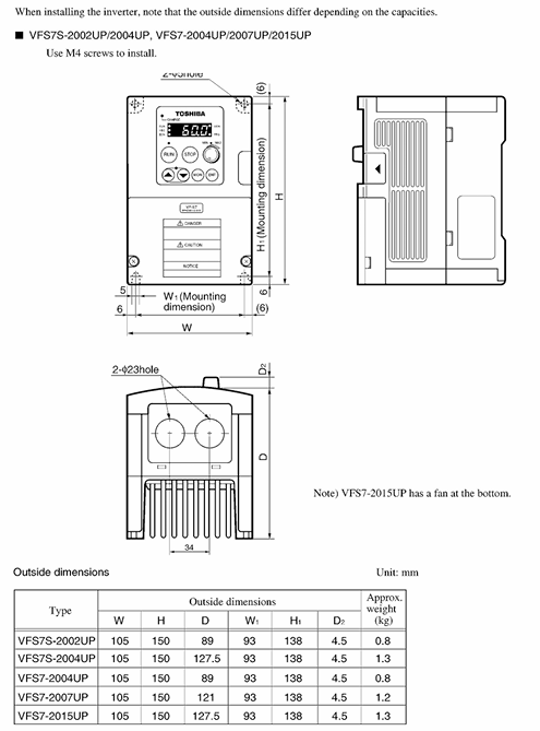
Installation method:
200V level (≤ 75kW), 400V level (≤ 75kW): Only supports vertical wall mounted installation and needs to be fixed on a metal bracket with a load-bearing capacity of ≥ twice the weight of the frequency converter.
400V level (≥ 90kW), high voltage level: floor mounted, requiring a dedicated base with a height of ≥ 10cm (to prevent water damage on the ground).
Environmental restrictions:
Temperature: -10 ℃~40 ℃ (up to 50 ℃ for models without casing), exceeding this range requires the installation of a cooling fan or air conditioner.
Humidity: ≤ 90% RH, no condensation (dehumidification device needs to be installed in condensation environment).
Altitude: ≤ 1000m (for every 100m increase, the rated output power decreases by 1%, up to a maximum of 3000m).
Vibration: Acceleration ≤ 0.6G (10-50Hz), amplitude ≤ 0.08mm (50-150Hz), exceeding it requires the installation of damping pads.
Ventilation gap (Figure 2-1):
Model power, top/bottom gap, left/right side gap, back gap
≤75kW ≥10cm ≥5cm ≥10cm
90-220kW ≥15cm ≥10cm ≥15cm
≥250kW ≥20cm ≥15cm ≥20cm
2. Wiring specifications
(1) Main circuit wiring (power segment differences)
200V level (0.4-75kW) and 400V level (0.75-37kW) (Figure 3-1):
Terminal name, function, wiring requirements
The R/L1, S/L2, and T/L3 three-phase power inputs require a circuit breaker (MCCB) with a capacity of 1.2-1.5 times the rated current of the frequency converter
U. The output of the V and W 3-phase motors corresponds to the U, V, and W terminals of the motor, and can be reversed to exchange any two phases
PE protection grounding Class 3 grounding, grounding resistance ≤ 10 Ω, wire diameter ≥ 1/2 of the main circuit power wire diameter
When the B1 and B2 braking units/resistors need to be connected for braking, an external braking unit can be connected. If the power is ≤ 15kW, an internal braking resistor can be connected
400V level (≥ 45kW) and high voltage level (Figure 3-2):
Add "input reactor terminals (L1R, L2S, L3T)" and force external input reactors (to suppress harmonics and protect power modules).
The brake terminals are divided into "B1, B2 (main brake)" and "B3, B4 (auxiliary brake)", suitable for high-power braking requirements.
(2) Control circuit wiring
Analog inputs (AI1, AI2):
AI1: Default 0-10VDC (frequency command), can be switched to 4-20mA (load resistance ≤ 500 Ω) through parameter P07.01.
AI2: Default 4-20mA (torque command), switchable to 0-10VDC (parameter P07.02).
Switching input (DI1-DI8):
Default functions: DI1=forward rotation, DI2=reverse rotation, DI3=multi speed 1, DI4=multi speed 2, DI5=jog, DI6=reset, DI7=emergency stop, DI8=allowed operation.
Input method: leakage/source type optional (parameter P06.01), voltage 24Vdc ± 10%, current ≤ 10mA.
Communication interface:
Standard RS485 interface (terminals TX+, TX -, RX+, RX -), supports MODBUS-RTU protocol, baud rate 9600-115200bps (parameter P20.01).
Optional PROFINET (P21 parameter group) and EtherNet/IP (P22 parameter group) communication modules require separate wiring.
(3) Wiring taboos
Do not connect power factor compensation capacitors at the motor or power supply end (as it may cause overvoltage tripping of the frequency converter).
The control circuit cable needs to be shielded twisted pair (wire diameter 0.5-1.0mm ²), with a distance of ≥ 20cm from the main circuit cable, to avoid parallel wiring (reduce interference).
High voltage level frequency converters need to be separately connected to the high-voltage grounding grid and are prohibited from being grounded together with low-voltage equipment.
Operation process and core function settings
1. Operation panel and basic operations
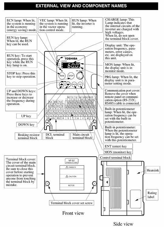
Panel layout (Figure 4-1): including a 5.7-inch LCD display screen (supporting Chinese/English switching), parameter knob (setting values), function keys (RUN/STOP/RESET/ESC/ENTER), and status indicator lights (power/run/fault).
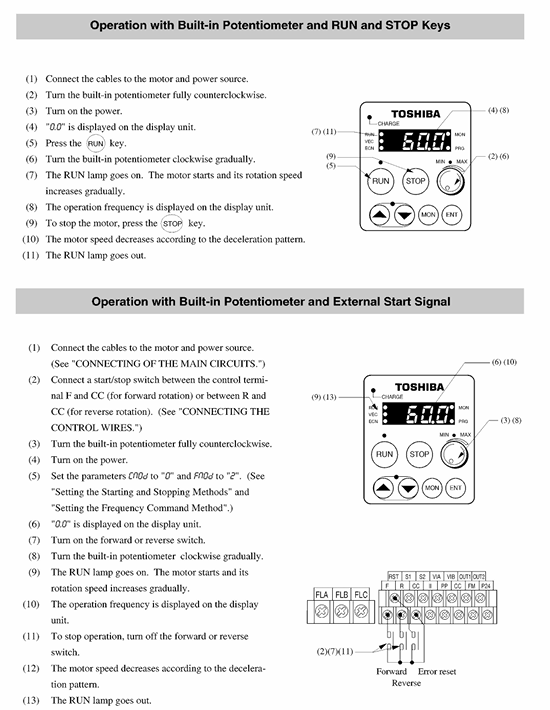
Basic operation process (trial operation):
Power on: MCCB is closed, and the panel displays the "TOSHIBA" logo before entering the standby interface (displaying "0.0Hz").
Switch control mode: Press the "MODE" key, select "Panel Control" (parameter P05.01=0), and the "PANEL" indicator light will turn on.
Set frequency:
Knob adjustment: Rotate the parameter knob to the target frequency (such as 50Hz) and press "ENTER" to save.
Number input: Press the "NUM" key, enter "50", press "ENTER", and the display screen will show "50.0Hz".
Start/Stop: Press the "RUN" button to accelerate the frequency converter to the set frequency; Press the "STOP" button to slow down and stop (default soft stop time is 5 seconds, parameter P03.02 is adjustable).
2. Core functions and parameter settings
(1) Control mode setting (parameter P01 group)
Parameter code, parameter name, function description, optional values, default values, applicable scenarios
P01.01 Control mode selection switch V/f/SVC/FVC mode 0=V/f, 1=SVC, 2=FVC 1 (SVC) 0=fan/pump, 1=conveyor/machine tool, 2=high-precision speed regulation
P01.02 V/f Curve Type Voltage Frequency Relationship in V/f Mode 0=Linear, 1=Square (Fan/Pump), 2=Custom 1 1=Energy saving, 2=Special Load
P01.03 Torque Boost: In SVC/FVC mode, the starting torque compensation ranges from 0.0% to 30.0%, and increases when the low-speed starting torque is insufficient (such as for cranes)
(2) Torque control function (parameter P04 group)
Torque limit: P04.01 (forward torque limit), P04.02 (reverse torque limit), range 0-200% rated torque, default 150% (to prevent overload).
Torque following: enabled when P04.05=1, torque is controlled through AI2 input 4-20mA signal, suitable for coiling machines and tension control equipment.
Zero speed torque maintenance: When P04.08=1, 0Hz can maintain 150% of the rated torque (requiring FVC mode+encoder feedback), suitable for elevators and hoists.
(3) Multi speed and brake control
Multi speed operation (parameter P08 group):
Supports 16 speeds (S1-S16), selected through DI3-DI6 terminal combination (such as DI3=ON → S1, DI3+DI4=ON → S2).
Each speed value is set through P08.01 (S1) - P08.16 (S16), with a range of 0.0-400.0 Hz.
Brake control (parameter P09 group):
DC injection braking: P09.01=1 enabled, starting frequency 0-10Hz (P09.02), braking voltage 0-30% (P09.03), braking time 0.1-10.0 seconds (P09.04), suitable for precise positioning.
Regenerative braking: P09.10=1 enabled, requires external braking unit (400V level ≥ 45kW forced external connection), braking torque 0-100% (P09.11), suitable for inertial loads (such as centrifuges).
(4) Energy saving function (parameter P15 group)
Fan/pump energy-saving mode (P15.01=1): Automatically adjusts the output voltage according to the load current, saving 5-15% energy compared to the normal V/f mode.
Automatic sleep/wake-up (P15.05=1): When the frequency is below the sleep threshold (P15.06, default 5.0Hz) and the duration exceeds the set value (P15.07, default 10 seconds), the inverter will shut down; Automatically wake up when the load increases.
Troubleshooting and Maintenance
1. Common fault codes and solutions
Fault code, fault type, possible causes, and solutions
OC1 acceleration overcurrent 1. The acceleration time is too short; 2. Motor short circuit; 3. Excessive load: 1. Increase P03.01 (acceleration time); 2. Check the insulation of the motor winding; 3. Reduce load or replace high-power frequency converter
OH1 power module overheating 1. Cooling fan failure; 2. Insufficient ventilation gap; 3. If the ambient temperature is too high, replace the fan (model FS-1238); 2. Adjust the installation spacing to the standard value; 3. Install a heat dissipation device
OV1 DC bus overvoltage: 1. The power supply voltage is too high; 2. Excessive regenerative energy; 3. The deceleration time is too short. 1. Check the grid voltage (within ± 10% of the rated voltage); 2. External braking unit; 3. Increase P03.02 (deceleration time)
GF grounding fault 1. Motor grounding short circuit; 2. Internal grounding of the frequency converter; 3. Cable damage: 1. Use a megohmmeter to measure the insulation of the motor (≥ 500M Ω); 2. Contact after-sales maintenance; 3. Replace damaged cables
Err12 communication fault: 1. Communication cable disconnected; 2. Baud rate mismatch; 3. Incorrect slave station address. 1. Check the RS485 wiring; 2. Unified master-slave station baud rate (P20.01); 3. Confirm the slave station address (P20.02)
2. Maintenance plan
Regular inspection (every 6 months):
Appearance inspection: Check whether the cabinet is deformed, whether the cables are damaged, and whether the terminals are oxidized.
Tightening inspection: Main circuit terminal screws (torque values see Table 5-1) and control circuit terminal screws to prevent loosening and heating.
Heat dissipation cleaning: Use compressed air (below 0.3MPa) to clean the dust on the heat dissipation fan and fins. If the fan makes abnormal noise, it needs to be replaced.
Insulation test: Disconnect the power supply and use a 500V megohmmeter to measure the insulation of the main circuit (≥ 10M Ω) and control circuit (≥ 100M Ω).
Regular testing (every 2 years):
Capacitor detection: Measure the capacitance of the DC bus (attenuation ≤ 20% is normal). If it exceeds the tolerance, it needs to be replaced (model CBB65).
Module detection: Use a multimeter to test the conductivity of the power module (IGBT), and replace the module if there is an abnormality.
Parameter backup: Back up the current parameters through the panel or software to prevent parameter loss.
Long term storage (≥ 6 months):
Environment: Temperature -20~40 ℃, humidity ≤ 60%, no corrosive gases.
Activation: Power on every 6 months (no load, voltage gradually increases from 0 to rated value for 30 minutes) to prevent capacitor aging.
Optional accessories and warranty terms
Optional accessories:
Accessory Type Model Example Function Applicable Scenarios
Input reactor ACL-4055 suppresses grid harmonics and protects power modules with 400V level ≥ 45kW mandatory selection
Braking unit BU-4220 enhances regenerative braking capability and absorbs braking energy inertia load (centrifuge, elevator)
The communication module MOD-PN supports PROFINET communication to achieve industrial Ethernet control of automated production lines
External control panel OP-S7 remote operation, cable length 1-10m. The frequency converter is installed inside the control cabinet and is inconvenient to operate directly
Filter EMI-4037 suppresses electromagnetic interference and meets EN 55011 standard near medical equipment and precision instruments
Warranty terms:
Warranty period: 12 months from the date of delivery, and 3 months for parts warranty.
Warranty scope: Malfunctions caused by equipment quality issues, including repair and replacement of parts.
Warranty expiration situation:
Unauthorized disassembly or modification of the frequency converter (such as replacing non original parts).
Installation/wiring does not comply with the instructions (such as poor grounding, overvoltage operation).
Damage caused by natural disasters (earthquakes, floods), power grid failures (lightning strikes, voltage surges).
Used for non industrial purposes (such as household appliances) or operating beyond rated parameters (such as overload, overclocking).
- YOKOGAWA
- Reliance
- ADVANCED
- SEW
- ProSoft
- WATLOW
- Kongsberg
- FANUC
- VSD
- DCS
- PLC
- man-machine
- Covid-19
- Energy and Gender
- Energy Access
- Renewable Integration
- Energy Subsidies
- Energy and Water
- Net zero emission
- Energy Security
- Critical Minerals
- A-B
- petroleum
- Mine scale
- Sewage treatment
- cement
- architecture
- Industrial information
- New energy
- Automobile market
- electricity
- Construction site
- HIMA
- ABB
- Rockwell
- Schneider Modicon
- Siemens
- xYCOM
- Yaskawa
- Woodward
- BOSCH Rexroth
- MOOG
- General Electric
- American NI
- Rolls-Royce
- CTI
- Honeywell
- EMERSON
- MAN
- GE
- TRICONEX
- Control Wave
- ALSTOM
- AMAT
- STUDER
- KONGSBERG
- MOTOROLA
- DANAHER MOTION
- Bentley
- Galil
- EATON
- MOLEX
- Triconex
- DEIF
- B&W
- ZYGO
- Aerotech
- DANFOSS
- KOLLMORGEN
- Beijer
- Endress+Hauser
- schneider
- Foxboro
- KB
- REXROTH
- YAMAHA
- Johnson
- Westinghouse
- WAGO
- TOSHIBA
- TEKTRONIX
- BENDER
- BMCM
- SMC
- HITACHI
- HIRSCHMANN
- XP POWER
- Baldor
- Meggitt
- SHINKAWA
- Other Brands
- UniOP
- KUKA
- IBA
- Beckhoff
-
ADLINK CPCI-6860A - 51-31310-OB10 industrial motherboard CompactPCI SBC
-
ADLINK AmITX-SL-G-H110 - 51-7A104-0A30 Mini-ITX Industrial Motherboard
-
ADLINK PXI-2005-003 - CPCI Industrial PC Data Acquisition Card Multi-Function DAQ
-
ADLINK DININ-814M - 51-14032-0A3D SCSI-100P cable connection Interface Terminal Board
-
ADLINK CPCI-3920NA/C2D15/M1G - 3U CompactPCI Intel Core 2 Duo Single Board Computer
-
ADLINK PCIE-8560 - 51-18014-0A20 Communication Card High Speed DAQ
-
ADLINK PCI-C154+ - Motion Control Card 4-axis Motion Controller Board
-
ADLINK PCI-RTV24 - image capture card Analog Video Frame Grabber
-
ADLINK NuPRO-842LV/P - 51-41360-0B30 Industrial Motherboard CPU Board
-
ADLINK cBP-3208/3208R - CPCI Board 3U 8-Slot CompactPCI Backplane
-
ADLINK PCI-8164 - 4-Axis Motion Controller PCI Card 51-12406-0A40
-
ADLINK PCIe-GIE64+ - 4-CH GigE Vision PoE+ Frame Grabber Video Capture Card
-
ADLINK CPCI-6860 / 6860A - CompactPCI Dual Xeon Single Board Computer
-
ADLINK IEC-915GV - REV 1.1 Industrial motherboard CPU Board
-
ADLINK ND-6520 - Technology RS-232 to RS-422RS-485 Converter NuDAM Module
-
ADLINK RTV-24 / PCI-MP4S - 51-12519-1C30 4-Channel Real Time Video Capture Board
-
ADLINK cPCI-6910 / cPCI-6910AM/M1G - cPCI-6910AM/DXL16/M1G/S80G(G)-3120 BOARD CompactPCI SBC
-
ADLINK NUPRO-A40H - Linghua 51-41807-1A30 Industrial Control Computer Motherboard
-
ADLINK USB-3488A - USB to GPIB INTERFACE USB-3488A(G) Controller Module
-
ADLINK PCI-8134A - motion control card 4-Axis Controller Card
-
ADLINK PCI-7432 - Board 32-Channel input / 32-output Isolated Digital I/O PCI Card
-
ADLINK PCI-8134A - 51-12421-0A10 motion controller card tested
-
ADLINK LPCIe-7230 - 32 CH Isolated Input/output Card 2 Interrupts Low Profile PCIe
-
ADLINK NuPRO-E340 - industrial computer motherboard 51-47807-0A30 PICMG 1.3 SHB
-
ADLINK PCI-7434 - High-speed Digital Acquisition Card 64-CH Isolated DO Card
-
ADLINK NuPRO-E330 - 51-41805-0A20 Indsutrial Board SHB Single Board Computer
-
ADLINK PCI-7248 - OPTO-22 48 CHANNEL DIO DIGITAL TTL/DTL I/O 51-12006-0A40 GP
-
ADLINK PCI-8134 - Motion control card 4-Axis Controller Card
-
ADLINK AMP-208C - Movimiento Control Tarjeta 51-12420-1A20 W/Expansión & Breakout
-
ADLINK PCI-8164 - 51-12406-0A40 PCB Board 4-Axis Motion Controller Card
-
ADLINK DIN-68Y-SGII / DIN-68M-J3A - Terminal Board Connector Interface Block
-
ADLINK PCIe-7432 - Technology 51-18402-0A10 PCIe Card With High Input Range
-
ADLINK PCI-8144 / PCI-8144N - Motion control card 4-Axis Stepper Controller Card
-
ADLINK HSL-HUB3/REPEATER - HIGH SPEED LINK EXTENSION MODULES Distributed Hub Module
-
ADLINK ND-6017 - Data Logging + Acquisition 8CH A/D input Mod NuDAM Module
-
ADLINK LPCIe-7250 - data acquisition card Low Profile 8-CH Relay Output Card
-
ADLINK PCI-7432 - I/O card 64-CH Isolated Digital Input Output PCI Card
-
ADLINK IMB-M43H - industrial control computer motherboard Q87 Chip Micro-ATX
-
ADLINK MP-C154 - Motion control Card 4-Axis Motion Controller Board
-
ADLINK PCI-RTV24 - image capture card Video Frame Grabber Card
-
ADLINK PCI-7250 - 8-CH Relay Output & 8-CH Isolated DI Card
-
ADLINK PCI-6308V - 8-CH 12-Bit Isolated Analog Output PCI Card PCB-I-E-1148=6EX2
-
ADLINK PCI-7248 - capture card 48-CH Opto-22 Compatible DIO Card
-
ADLINK HSL-AI16A02-M-VV - Analog Input Output Distributed Module
-
ADLINK NuPRO-A301 - Rev:1.4 NUPRO-A301 PICMG Full-Size Single Board Computer
-
ADLINK PCI-6208V-GL - 8-CH Voltage Analog Output PCI Card
-
ADLINK PCI-8134A - 51-12421-0A10 4-Axis Motion Controller Card
-
ADLINK MNET-S23 - TECHNOLOGY MNET S23 - SERVO DRIVER CONTROL MODULE
-
ADLINK M-342 - ATX I3 I5 I7 Q67 Industrial Motherboard
-
ADLINK NUPRO-780 - Industrial Motherboard CPU Board PICMG SBC
-
ADLINK MP-C154 / MP-C152 - 4-Axis Motion Control Card Pulse-Train Controller
-
ADLINK NuPRO-935A/LV10B0 - Motherboard 51-41802-0A10 GP w/RAM Industrial Control Board
-
ADLINK MP-C154 - Motion control card 4-Axis Motion Controller Mainboard
-
ADLINK PCI-7250 - PCI Acquisition Card 8-CH Relay Output Isolated DI Card
-
ADLINK ACL-7124 - Technology Inc.24 DIO Card Digital Input Output Card
-
ADLINK PCI-8554 A2 - Timer/Counter Data Acquisition Card
-
ADLINK DIN-825-GP4 - Terminal Block Interface Board Breakout Module
-
ADLINK NuPR0-761 - REV:1.1 Industrial motherboard Full-Size PICMG SBC
-
ADLINK MXE-1401/M8G (G) - Matrix Fanless Embedded Computer Industrial PC
-
ADLINK HSL-DI16DO16-UD-NN - Digital 16 Channel I/O Mod Distributed I/O Module
-
ADLINK ND6520 - NUDAM INTELLIGENT DA&C MODULE RS232-RS-422/RS485 CONVERTOR
-
ADLINK NUPRO-761 - REV:1.1 Industrial Motherboard CPU Board
-
ADLINK AMP-208C - Motion Control Card 51-12420-1A20 DSP-based 8-axis
-
ADLINK NuPRO-A301REV 1.4 - with packaging industrial computer motherboard PICMG SBC
-
ADLINK PCM-9112+ - 51-12300-0A2 industrial motherboard Multi-Function DAQ PC/104 Module
-
ADLINK PCM-7250+ - 8-CH Relay Outputs & 8-CH Isolated DI Module PC/104
-
ADLINK PCI-RTV24 - Image capture card Analog Video Frame Grabber
-
ADLINK PCI-8134 - Motion Controller PCI Card 4-Axis Controller Board
-
ADLINK PCI-7432 - Isolated Digital I/O PCI Card
-
ADLINK PCI-8554 A2 - acquisition card Timer/Counter Card
-
ADLINK PCI-8132 - Rev.A2 2-Axis Servo & Stepper Motion Controller Card
-
ADLINK PCI-8132 - Data Acquisition card 2-Axis Motion Controller Card
-
ADLINK EBP-13E4 - 51-46703-0A30 Industrial Backplane Board Passive Backplane
-
ADLINK PCI-800L - Electronic Card Interface Controller Card
-
ADLINK PCIe-GIE72 - 51-18531-0A10 PCB Board GigE Vision Frame Grabber
-
ADLINK DAQ-2010(G)-OOBO - Simultaneous-Sampling Multi-Function DAQ Card
-
ADLINK PCI-9112 - REV.B1 Multifunction DAQ Card Data Acquisition Card
-
ADLINK PCI-7230 - 51-12003-DA60 32-CH Isolated Digital I/O Card
-
ADLINK PCI-7432 - Data Acquisition Card Isolated Digital I/O PCI Card
-
ADLINK ETX-AT-N270-18/LXE - 51-71111-0A20 ETX CPU Module Motherboard
-
ADLINK HSL-DI32-UD-N - DIGITAL INPUT 32 POINTS MODULE Distributed I/O
-
ADLINK AMP-204C - Motion Control card DSP-Based 4-Axis Advanced Controller
-
ADLINK MNET-4XMOG-0050 - Four-axis Motion Controller Distributed Motion Module
-
ADLINK AMP-204C - Motion control card DSP-Based 4-Axis Pulse-Train Controller
-
ADLINK PCI-7442 - Switch card 64-Channel Datalogging & Acquisition Card
-
ADLINK M-302 - Industrial control motherboard ATX PC Board
-
ADLINK NUPRO-852 / NUPRO-852LV - Industrial motherboard Single Board Computer
-
ADLINK PCI-8134 - REV.B1. 4-Axis Motion Controller Card
-
ADLINK PCI-GIE62 + - 51-18502-0A20 2-CH GigE Vision Frame Grabber PoE Card
-
ADLINK PCI-MPG24 - 51-12523-0B20 MPEG4 Card Video Compression Hardware
-
ADLINK HSL-TB32-M-DIN - 32-CH I/O TERMINAL W/ HSL-AI16AO2-M-VV MODULE
-
ADLINK PCI-M114-GL - PCB Ver 2.1 Motion Controller Axis Card
-
ADLINK IMB-M40H - SYM76996H61 motherboard Industrial Computer Mainboard
-
ADLINK NUPRO-A40H - 51-41807-1A20 industrial control motherboard H61 Chip
-
ADLINK PCI-M114-GL - Axis Card Data Acquisition Card PCB VER2.2 Motion Controller
-
ADLINK PCI-8134 - Motion Controller PCI Card 4-Axis Controller Board
-
ADLINK PCI-8102 - Motion control card 2-Axis Servo & Stepper Controller
-
ADLINK NuPRO-841REV:3.0 - motherboard Industrial Control PC Board
-
ADLINK HSL-TB32-U-DIN REV A1 - Breakout Terminal Board Field I/O Module
-
ADLINK AMP-204C - Motion Control card DSP-Based 4-Axis Pulse-Train Controller
-
ADLINK NUPRO-A40H - 51-41807-1A20 industrial control motherboard H61 PC Board
-
ADLINK PCI-6308A / PCI-6308V - 51-12202-0A50 Isolated Analog Output Card
-
ADLINK AMP-204C - DSP-Based 4-Axis Advanced Pulse-Train Motion Controller
-
ADLINK PCI-7434 - Technology 64-Channel Isolated Digital I/O PCI Cards
-
ADLINK CPCI-6840 / CPCI-6840V / PM16/M1G-12G0 - CompactPCI Single Board Computer CPU Module
-
ADLINK PCIE-GIE74 - Motherboard Video Capture Card 51-18531-0A10 Frame Grabber
-
ADLINK NuPRO-E330 - industrial computer equipment motherboard Control Mainboard
-
ADLINK AMP-208C / 51-12420-1A20 - Motion Control Card W/ Expansion & Breakout Board
-
ADLINK HPCI-14S12U - industrial computer baseboard Passive Backplane 14 Slots
-
ADLINK PCI-8164 - 4-Axis Motion Controller PCI Card W/ 1x Cable, 1x Breakout Box
-
ADLINK PCIe-RTV24 - 51-18016-0A20 Image Acquisition Video Capture Card
-
ADLINK M-342 - 5 PCI ATX Motherboard Industrial PC Mainboard
-
ADLINK PCI-FIW64 - 4/2 Channel IEEE1394B Image Capture Card FireWire Frame Grabber
-
ADLINK PCI-7432 - digital IO card 64-CH Isolated Digital Input Output Card
-
ADLINK 51-12001-0C20 - Circuit Board PCI-7200 Data Acquisition Controller Card
-
ADLINK PXI-3920 - PXI 3U cPCI Industrial Controller Embedded System CPU Board
-
ADLINK NuPRO-841REV:2.0 - motherboard Industrial Control PC Board
-
ADLINK NuPro-E330 - 51-41805-0A20 PCB Industrial Control Computer Motherboard
-
ADLINK PCI-RTV24 - Image capture card Analog Video Frame Grabber
-
ADLINK PCI-7442 - Switch card 64-Channel Datalogging & Acquisition Card
-
ADLINK HPX-13S4 - device baseboard Passive Backplane Riser Card
-
ADLINK PCI-9112 REV A.1 - Multi Function DA&C Board Data Acquisition Card
-
ADLINK PCI-7248 - 51-12006-0A40 Card Control 48-CH Digital I/O Module
-
ADLINK CPCI-6860 / 6860A - motherboard CompactPCI Dual Xeon Single Board Computer
-
ADLINK DPAC-3020-11(G) - Embedded PC Automation Controller Machine Control Board
-
ADLINK NuPRO-841 REV:1.0 - industrial control motherboard CPU Board
-
ADLINK MNET-4XMOG-0050 - Four-axis Motion Controller MNET Motion Control Card
-
ADLINK ETX-AT-N270-18/LXE - 51-71111-0A20 ETX CPU Module Motherboard

K-JIANG

Add: Jimei North Road, Jimei District, Xiamen, Fujian, China
Tell:+86-15305925923