
K-WANG


TOSHIBA TOSBERT S11 series frequency converter
TOSHIBA TOSBERT S11 series frequency converter
Document Overview and Basic Equipment Information
Document positioning: The official user manual for Toshiba TOSBERT S11 series frequency converters is designed for electrical engineers and maintenance personnel, covering the entire process of equipment installation, wiring, operation, parameter setting, fault handling, and maintenance, highlighting the characteristics of "compact" and "high compatibility".
Equipment specifications and models:
Voltage level, power range, input type, applicable scenarios, typical models
200V level 0.1-1.5kW single-phase small equipment (laboratory instruments, household equipment) S11-2001S (0.1kW), S11-2015S (1.5kW)
200V level 2.2-15kW three-phase small and medium-sized motors (conveyors, packaging machines) S11-2002H (2.2kW), S11-2015H (15kW)
400V level 0.4-30kW three-phase medium and large equipment (fans, pumps, small machine tools) S11-4004H (0.4kW), S11-4030H (30kW)
Model coding rules: Taking "S11-4015H-C" as an example, the meanings of each part are:
S11: Series Code (TOSBERT S11 Series)
4: Voltage level (2=200V level, 4=400V level)
015: Capacity (15kW, 0.1kW model standard 001)
H: Basic configuration (H=standard, S=simple, L=low noise)
C: Optional functions (C=built-in communication module, F=built-in braking unit)
Core technical features:
Ultra compact design: The volume is reduced by 30% compared to the previous generation S7 series, and the size of the 0.4kW model is only 75 × 130 × 100mm, saving control cabinet space.
High protection and compatibility: basic model IP20, optional IP40 (anti solid foreign object+anti splash water); Compliant with NEMA ISO14001 Part 31, fully compatible with variable frequency drive, suitable for various asynchronous motors.
Control accuracy: In sensorless vector (SVC) mode, the output is 150% of the rated torque at 0.5Hz, with a speed accuracy of ± 0.1%, meeting the high-precision requirements of small and medium power.
Installation specifications and environmental requirements
1. Installation method (segmented by power)
Power Range Installation Method Installation Requirements Applicable Scenarios
≤ 0.4kW (200V single-phase/400V three-phase) DIN rail installation compatible with 35mm standard DIN rail, rail length ≥ inverter width, installation surface flatness ≤ 0.5mm Small control cabinet, distributed installation
≥ 0.75kW (200V three-phase/400V three-phase) vertical wall mounted installation fixed on a metal backplate with a thickness of ≥ 1.5mm, backplate grounded (≤ 10 Ω), screw torque 2.5-4.0N · m, medium-sized control cabinet, centralized installation
All models (IP40 configuration) require a larger ventilation gap (≥ 5cm on both sides) to be reserved for independent installation. It is prohibited to be in close proximity to heating equipment (such as contactors) in dusty/humid environments (such as food processing workshops)
2. Ventilation gaps and environmental restrictions
Ventilation gap (Figure 2-1):
Protection level: Top gap, bottom gap, left and right gap, back gap
IP20 ≥5cm ≥5cm ≥3cm ≥5cm
IP40 ≥8cm ≥8cm ≥5cm ≥8cm
Environmental restrictions:
Temperature: IP20 model -10 ℃~40 ℃, IP40 model -10 ℃~50 ℃; For every 1 ℃ increase in overheating, the rated power decreases by 1% (up to a maximum of 50 ℃).
Humidity: ≤ 90% RH, no condensation (condensation environment requires IP40+anti condensation heater).
Altitude: ≤ 1000m (over 1000m, power reduction of 1% per 100m, up to 3000m).
Vibration: Acceleration ≤ 0.5G (10-50Hz), amplitude ≤ 0.08mm (50-150Hz), exceeding the range requires adding or removing vibration pads.
3. Transportation and Storage
Transportation: Fill the packaging box with cushioning material, do not invert/flip it over, and avoid collision (to prevent damage to internal capacitors and modules).
Storage: Temperature -20 ℃~60 ℃, humidity ≤ 60% RH; long-term storage (≥ 6 months). Power on for 30 minutes every 6 months (no load) to activate the capacitor.
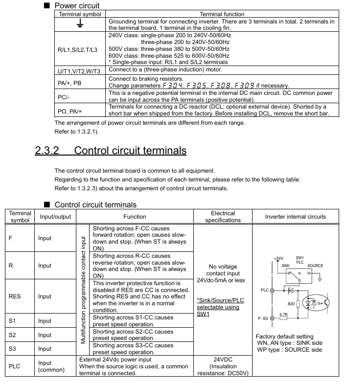
Wiring specifications and hardware configuration
1. Main circuit wiring (with differences in power segments)
(1) 200V level (single-phase/three-phase) main circuit terminal
Terminal identification function wiring requirements cable specifications (copper core)
L/N (single-phase), L1/L2/L3 (three-phase) power input series MCCB (capacity=1.2-1.5 × rated current), prohibit connecting compensating capacitors 0.1-0.75kW: 0.75mm ²; 1.5-15kW:1.5-4mm²
U/V/W motor output corresponds to motor U/V/W, reverse exchange any two phases; Cable length ≤ 30m (over 30m with output reactor) consistent with input cable
PE protective grounding Class 3 grounding (≤ 10 Ω), yellow green dual color wire, prohibited from sharing ≥ 1/2 of input cable with neutral wire, minimum 0.75mm ²
B1/B2 brake resistor connection ≤ 7.5kW can be connected to a built-in resistor; 7.5kW requires an external connection of ≥ 1.5mm ² (optional according to braking power)
(2) 400V level main circuit terminal
Power ≤ 7.5kW: The terminal configuration is the same as 200V three-phase, with the addition of "input filter terminal (F1/F2)" and optional EMC filter.
Power ≥ 11kW: divided into "main power input (L1/L2/L3)" and "reactor input (L1R/L2S/L3T)", forced external input reactor (harmonic suppression, protection module).
2. Control circuit wiring
Analog input (AI1/AI2):
Terminal default function configurable function wiring requirements
AI1 0-10VDC (frequency command) 4-20mA (parameter P07.01) Load resistance ≤ 500 Ω, shielded twisted pair (0.5mm ²)
AI2 4-20mA (torque command) 0-10VDC (parameter P07.02) Same as AI1, cable length ≤ 20m
Switching input (DI1-DI6):
Default functions: DI1=forward rotation, DI2=reverse rotation, DI3=multi speed 1, DI4=multi speed 2, DI5=jog, DI6=reset.
Input method: leakage type (default)/source type optional (P06.01), 24Vdc ± 10%, current ≤ 8mA.
Communication interface:
Standard RS485 (terminals A/B), supports MODBUS-RTU, baud rate 9600-115200bps (P20.01).
Optional RS232 module (requires TX/RX/GND terminals) for direct communication with PC.
3. Wiring taboos
Do not connect compensation capacitors at the motor end (which may cause overvoltage tripping).
The distance between the control cable and the main circuit cable should be ≥ 15cm to avoid parallel wiring (reduce EMI interference).
After wiring the IP40 model, it is necessary to check whether the sealing ring is compacted to prevent dust/water vapor from entering.
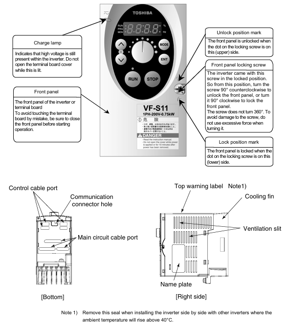
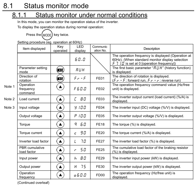
Operation panel and core operations
1. Analysis of the operation panel
Panel layout (Figure 4-1):
Display: 2-line LCD screen (supports Chinese/English, parameter P00.02 switching), displaying frequency, current, and fault codes.
Buttons: RUN, STOP, MODE, △/▽ (parameter adjustment), ENTER (confirm).
Indicator lights: Power (PWR), Run (RUN), Fault (ALM).
Menu structure: First level menu (monitoring/parameters/faults) → Second level menu (parameter group P00-P29) → Third level menu (specific parameters).
2. Basic operation process (panel control)
Power on standby: Close the MCCB, the PWR light is on, the screen displays "0.0Hz", and there is no ALM alarm.
Frequency setting: Press MODE to select "Panel Control", press △/▽ to set the target frequency (such as 50Hz), and confirm with ENTER.
Start/Stop: Press RUN to start (RUN light on), press STOP to soft stop (deceleration time P03.02 defaults to 3 seconds).
Fault reset: When the ALM light is on, press STOP for 2 seconds to reset after troubleshooting.
3. External/Communication Control Operations
External control: P05.01=1 (external mode), DI1 is connected to the forward switch, AI1 is connected to the potentiometer, and the switch is closed to start.
Communication control: P05.01=2 (communication mode), PC sends instructions through MODBUS (such as writing frequency 0x0001=5000 → 50Hz).
Core functions and parameter configuration
1. Control mode and key parameters
Control mode parameters (P01.01) core parameters applicable scenarios
V/f control 0 P01.02 (V/f curve: 0=linear, 1=square) Fan/pump (variable torque)
Sensorless vector (SVC) 1 P01.04 (vector gain: 0.1-10.0), P04.01 (torque limit: 50-200%) machine tool/conveyor (constant torque)
2. Multi speed and brake control
16 speed operation: P08.01-P08.16 set the 16 speed frequency (0.0-400.0Hz), and select the combination of DI3-DI6 (such as DI3=ON → S1).
DC injection braking: P09.01=1 (enabled), P09.02=0-10Hz (starting frequency), P09.03=0-30% (voltage), suitable for positioning scenarios.
3. Energy saving function
Fan/pump energy-saving: P15.01=1 (enabled), P15.02=1 (square curve), energy-saving of 5-12%.
Automatic sleep: P15.05=1, P15.06=5.0Hz (sleep threshold), P15.07=10 seconds (delay), light load shutdown energy-saving.
Troubleshooting and Maintenance
1. Common fault codes and solutions
Fault code type, cause, and solution measures
OC1 acceleration overcurrent acceleration time short, motor short circuit, large load increase P03.01, motor insulation measurement, load reduction
OH1 module overheating fan fault, insufficient gap, environmental heat exchange fan (FS-6015), gap adjustment, cooling
OV1 bus overvoltage, high grid voltage, short deceleration, high regenerative energy measurement grid voltage, increased P03.02, connected to braking unit
GF grounding fault motor grounding, cable damage, grounding difference measurement motor insulation, cable replacement, rectification of grounding (≤ 10 Ω)
Err12 communication fault, cable breakage, baud rate mismatch. Check RS485 wiring and unify P20.01 parameters
2. Maintenance plan
Periodic project operation
Monthly visual inspection to ensure that the casing/terminals are free from damage or oxidation
Tighten the main circuit screws every 6 months with a torque of 2.5-4.0N · m
Clean the compressed air (0.2MPa) fan/heat sink every 6 months to dissipate heat
Measure the capacitance of the busbar every 2 years (attenuation ≤ 20%) through capacitance testing
Optional accessories and warranty
Optional accessories:
Accessory model and function
Input reactor ACL-S11-04 suppresses harmonics and increases power factor to 0.95
Braking resistor BR-S11-10 is compatible with 15kW models and can absorb regenerative energy
MOD-S11-RS232 communication module expands RS232 communication
External panel OP-S11-1M 1-meter cable, remote operation
Warranty terms:
Deadline: 12 months for the host and 3 months for the accessories.
Failure situation: unauthorized modification, overvoltage operation, natural disasters, etc.
- YOKOGAWA
- Reliance
- ADVANCED
- SEW
- ProSoft
- WATLOW
- Kongsberg
- FANUC
- VSD
- DCS
- PLC
- man-machine
- Covid-19
- Energy and Gender
- Energy Access
- Renewable Integration
- Energy Subsidies
- Energy and Water
- Net zero emission
- Energy Security
- Critical Minerals
- A-B
- petroleum
- Mine scale
- Sewage treatment
- cement
- architecture
- Industrial information
- New energy
- Automobile market
- electricity
- Construction site
- HIMA
- ABB
- Rockwell
- Schneider Modicon
- Siemens
- xYCOM
- Yaskawa
- Woodward
- BOSCH Rexroth
- MOOG
- General Electric
- American NI
- Rolls-Royce
- CTI
- Honeywell
- EMERSON
- MAN
- GE
- TRICONEX
- Control Wave
- ALSTOM
- AMAT
- STUDER
- KONGSBERG
- MOTOROLA
- DANAHER MOTION
- Bentley
- Galil
- EATON
- MOLEX
- Triconex
- DEIF
- B&W
- ZYGO
- Aerotech
- DANFOSS
- KOLLMORGEN
- Beijer
- Endress+Hauser
- schneider
- Foxboro
- KB
- REXROTH
- YAMAHA
- Johnson
- Westinghouse
- WAGO
- TOSHIBA
- TEKTRONIX
- BENDER
- BMCM
- SMC
- HITACHI
- HIRSCHMANN
- XP POWER
- Baldor
- Meggitt
- SHINKAWA
- Other Brands
- UniOP
- KUKA
- IBA
- Beckhoff
-
ADLINK CPCI-6860A - 51-31310-OB10 industrial motherboard CompactPCI SBC
-
ADLINK AmITX-SL-G-H110 - 51-7A104-0A30 Mini-ITX Industrial Motherboard
-
ADLINK PXI-2005-003 - CPCI Industrial PC Data Acquisition Card Multi-Function DAQ
-
ADLINK DININ-814M - 51-14032-0A3D SCSI-100P cable connection Interface Terminal Board
-
ADLINK CPCI-3920NA/C2D15/M1G - 3U CompactPCI Intel Core 2 Duo Single Board Computer
-
ADLINK PCIE-8560 - 51-18014-0A20 Communication Card High Speed DAQ
-
ADLINK PCI-C154+ - Motion Control Card 4-axis Motion Controller Board
-
ADLINK PCI-RTV24 - image capture card Analog Video Frame Grabber
-
ADLINK NuPRO-842LV/P - 51-41360-0B30 Industrial Motherboard CPU Board
-
ADLINK cBP-3208/3208R - CPCI Board 3U 8-Slot CompactPCI Backplane
-
ADLINK PCI-8164 - 4-Axis Motion Controller PCI Card 51-12406-0A40
-
ADLINK PCIe-GIE64+ - 4-CH GigE Vision PoE+ Frame Grabber Video Capture Card
-
ADLINK CPCI-6860 / 6860A - CompactPCI Dual Xeon Single Board Computer
-
ADLINK IEC-915GV - REV 1.1 Industrial motherboard CPU Board
-
ADLINK ND-6520 - Technology RS-232 to RS-422RS-485 Converter NuDAM Module
-
ADLINK RTV-24 / PCI-MP4S - 51-12519-1C30 4-Channel Real Time Video Capture Board
-
ADLINK cPCI-6910 / cPCI-6910AM/M1G - cPCI-6910AM/DXL16/M1G/S80G(G)-3120 BOARD CompactPCI SBC
-
ADLINK NUPRO-A40H - Linghua 51-41807-1A30 Industrial Control Computer Motherboard
-
ADLINK USB-3488A - USB to GPIB INTERFACE USB-3488A(G) Controller Module
-
ADLINK PCI-8134A - motion control card 4-Axis Controller Card
-
ADLINK PCI-7432 - Board 32-Channel input / 32-output Isolated Digital I/O PCI Card
-
ADLINK PCI-8134A - 51-12421-0A10 motion controller card tested
-
ADLINK LPCIe-7230 - 32 CH Isolated Input/output Card 2 Interrupts Low Profile PCIe
-
ADLINK NuPRO-E340 - industrial computer motherboard 51-47807-0A30 PICMG 1.3 SHB
-
ADLINK PCI-7434 - High-speed Digital Acquisition Card 64-CH Isolated DO Card
-
ADLINK NuPRO-E330 - 51-41805-0A20 Indsutrial Board SHB Single Board Computer
-
ADLINK PCI-7248 - OPTO-22 48 CHANNEL DIO DIGITAL TTL/DTL I/O 51-12006-0A40 GP
-
ADLINK PCI-8134 - Motion control card 4-Axis Controller Card
-
ADLINK AMP-208C - Movimiento Control Tarjeta 51-12420-1A20 W/Expansión & Breakout
-
ADLINK PCI-8164 - 51-12406-0A40 PCB Board 4-Axis Motion Controller Card
-
ADLINK DIN-68Y-SGII / DIN-68M-J3A - Terminal Board Connector Interface Block
-
ADLINK PCIe-7432 - Technology 51-18402-0A10 PCIe Card With High Input Range
-
ADLINK PCI-8144 / PCI-8144N - Motion control card 4-Axis Stepper Controller Card
-
ADLINK HSL-HUB3/REPEATER - HIGH SPEED LINK EXTENSION MODULES Distributed Hub Module
-
ADLINK ND-6017 - Data Logging + Acquisition 8CH A/D input Mod NuDAM Module
-
ADLINK LPCIe-7250 - data acquisition card Low Profile 8-CH Relay Output Card
-
ADLINK PCI-7432 - I/O card 64-CH Isolated Digital Input Output PCI Card
-
ADLINK IMB-M43H - industrial control computer motherboard Q87 Chip Micro-ATX
-
ADLINK MP-C154 - Motion control Card 4-Axis Motion Controller Board
-
ADLINK PCI-RTV24 - image capture card Video Frame Grabber Card
-
ADLINK PCI-7250 - 8-CH Relay Output & 8-CH Isolated DI Card
-
ADLINK PCI-6308V - 8-CH 12-Bit Isolated Analog Output PCI Card PCB-I-E-1148=6EX2
-
ADLINK PCI-7248 - capture card 48-CH Opto-22 Compatible DIO Card
-
ADLINK HSL-AI16A02-M-VV - Analog Input Output Distributed Module
-
ADLINK NuPRO-A301 - Rev:1.4 NUPRO-A301 PICMG Full-Size Single Board Computer
-
ADLINK PCI-6208V-GL - 8-CH Voltage Analog Output PCI Card
-
ADLINK PCI-8134A - 51-12421-0A10 4-Axis Motion Controller Card
-
ADLINK MNET-S23 - TECHNOLOGY MNET S23 - SERVO DRIVER CONTROL MODULE
-
ADLINK M-342 - ATX I3 I5 I7 Q67 Industrial Motherboard
-
ADLINK NUPRO-780 - Industrial Motherboard CPU Board PICMG SBC
-
ADLINK MP-C154 / MP-C152 - 4-Axis Motion Control Card Pulse-Train Controller
-
ADLINK NuPRO-935A/LV10B0 - Motherboard 51-41802-0A10 GP w/RAM Industrial Control Board
-
ADLINK MP-C154 - Motion control card 4-Axis Motion Controller Mainboard
-
ADLINK PCI-7250 - PCI Acquisition Card 8-CH Relay Output Isolated DI Card
-
ADLINK ACL-7124 - Technology Inc.24 DIO Card Digital Input Output Card
-
ADLINK PCI-8554 A2 - Timer/Counter Data Acquisition Card
-
ADLINK DIN-825-GP4 - Terminal Block Interface Board Breakout Module
-
ADLINK NuPR0-761 - REV:1.1 Industrial motherboard Full-Size PICMG SBC
-
ADLINK MXE-1401/M8G (G) - Matrix Fanless Embedded Computer Industrial PC
-
ADLINK HSL-DI16DO16-UD-NN - Digital 16 Channel I/O Mod Distributed I/O Module
-
ADLINK ND6520 - NUDAM INTELLIGENT DA&C MODULE RS232-RS-422/RS485 CONVERTOR
-
ADLINK NUPRO-761 - REV:1.1 Industrial Motherboard CPU Board
-
ADLINK AMP-208C - Motion Control Card 51-12420-1A20 DSP-based 8-axis
-
ADLINK NuPRO-A301REV 1.4 - with packaging industrial computer motherboard PICMG SBC
-
ADLINK PCM-9112+ - 51-12300-0A2 industrial motherboard Multi-Function DAQ PC/104 Module
-
ADLINK PCM-7250+ - 8-CH Relay Outputs & 8-CH Isolated DI Module PC/104
-
ADLINK PCI-RTV24 - Image capture card Analog Video Frame Grabber
-
ADLINK PCI-8134 - Motion Controller PCI Card 4-Axis Controller Board
-
ADLINK PCI-7432 - Isolated Digital I/O PCI Card
-
ADLINK PCI-8554 A2 - acquisition card Timer/Counter Card
-
ADLINK PCI-8132 - Rev.A2 2-Axis Servo & Stepper Motion Controller Card
-
ADLINK PCI-8132 - Data Acquisition card 2-Axis Motion Controller Card
-
ADLINK EBP-13E4 - 51-46703-0A30 Industrial Backplane Board Passive Backplane
-
ADLINK PCI-800L - Electronic Card Interface Controller Card
-
ADLINK PCIe-GIE72 - 51-18531-0A10 PCB Board GigE Vision Frame Grabber
-
ADLINK DAQ-2010(G)-OOBO - Simultaneous-Sampling Multi-Function DAQ Card
-
ADLINK PCI-9112 - REV.B1 Multifunction DAQ Card Data Acquisition Card
-
ADLINK PCI-7230 - 51-12003-DA60 32-CH Isolated Digital I/O Card
-
ADLINK PCI-7432 - Data Acquisition Card Isolated Digital I/O PCI Card
-
ADLINK ETX-AT-N270-18/LXE - 51-71111-0A20 ETX CPU Module Motherboard
-
ADLINK HSL-DI32-UD-N - DIGITAL INPUT 32 POINTS MODULE Distributed I/O
-
ADLINK AMP-204C - Motion Control card DSP-Based 4-Axis Advanced Controller
-
ADLINK MNET-4XMOG-0050 - Four-axis Motion Controller Distributed Motion Module
-
ADLINK AMP-204C - Motion control card DSP-Based 4-Axis Pulse-Train Controller
-
ADLINK PCI-7442 - Switch card 64-Channel Datalogging & Acquisition Card
-
ADLINK M-302 - Industrial control motherboard ATX PC Board
-
ADLINK NUPRO-852 / NUPRO-852LV - Industrial motherboard Single Board Computer
-
ADLINK PCI-8134 - REV.B1. 4-Axis Motion Controller Card
-
ADLINK PCI-GIE62 + - 51-18502-0A20 2-CH GigE Vision Frame Grabber PoE Card
-
ADLINK PCI-MPG24 - 51-12523-0B20 MPEG4 Card Video Compression Hardware
-
ADLINK HSL-TB32-M-DIN - 32-CH I/O TERMINAL W/ HSL-AI16AO2-M-VV MODULE
-
ADLINK PCI-M114-GL - PCB Ver 2.1 Motion Controller Axis Card
-
ADLINK IMB-M40H - SYM76996H61 motherboard Industrial Computer Mainboard
-
ADLINK NUPRO-A40H - 51-41807-1A20 industrial control motherboard H61 Chip
-
ADLINK PCI-M114-GL - Axis Card Data Acquisition Card PCB VER2.2 Motion Controller
-
ADLINK PCI-8134 - Motion Controller PCI Card 4-Axis Controller Board
-
ADLINK PCI-8102 - Motion control card 2-Axis Servo & Stepper Controller
-
ADLINK NuPRO-841REV:3.0 - motherboard Industrial Control PC Board
-
ADLINK HSL-TB32-U-DIN REV A1 - Breakout Terminal Board Field I/O Module
-
ADLINK AMP-204C - Motion Control card DSP-Based 4-Axis Pulse-Train Controller
-
ADLINK NUPRO-A40H - 51-41807-1A20 industrial control motherboard H61 PC Board
-
ADLINK PCI-6308A / PCI-6308V - 51-12202-0A50 Isolated Analog Output Card
-
ADLINK AMP-204C - DSP-Based 4-Axis Advanced Pulse-Train Motion Controller
-
ADLINK PCI-7434 - Technology 64-Channel Isolated Digital I/O PCI Cards
-
ADLINK CPCI-6840 / CPCI-6840V / PM16/M1G-12G0 - CompactPCI Single Board Computer CPU Module
-
ADLINK PCIE-GIE74 - Motherboard Video Capture Card 51-18531-0A10 Frame Grabber
-
ADLINK NuPRO-E330 - industrial computer equipment motherboard Control Mainboard
-
ADLINK AMP-208C / 51-12420-1A20 - Motion Control Card W/ Expansion & Breakout Board
-
ADLINK HPCI-14S12U - industrial computer baseboard Passive Backplane 14 Slots
-
ADLINK PCI-8164 - 4-Axis Motion Controller PCI Card W/ 1x Cable, 1x Breakout Box
-
ADLINK PCIe-RTV24 - 51-18016-0A20 Image Acquisition Video Capture Card
-
ADLINK M-342 - 5 PCI ATX Motherboard Industrial PC Mainboard
-
ADLINK PCI-FIW64 - 4/2 Channel IEEE1394B Image Capture Card FireWire Frame Grabber
-
ADLINK PCI-7432 - digital IO card 64-CH Isolated Digital Input Output Card
-
ADLINK 51-12001-0C20 - Circuit Board PCI-7200 Data Acquisition Controller Card
-
ADLINK PXI-3920 - PXI 3U cPCI Industrial Controller Embedded System CPU Board
-
ADLINK NuPRO-841REV:2.0 - motherboard Industrial Control PC Board
-
ADLINK NuPro-E330 - 51-41805-0A20 PCB Industrial Control Computer Motherboard
-
ADLINK PCI-RTV24 - Image capture card Analog Video Frame Grabber
-
ADLINK PCI-7442 - Switch card 64-Channel Datalogging & Acquisition Card
-
ADLINK HPX-13S4 - device baseboard Passive Backplane Riser Card
-
ADLINK PCI-9112 REV A.1 - Multi Function DA&C Board Data Acquisition Card
-
ADLINK PCI-7248 - 51-12006-0A40 Card Control 48-CH Digital I/O Module
-
ADLINK CPCI-6860 / 6860A - motherboard CompactPCI Dual Xeon Single Board Computer
-
ADLINK DPAC-3020-11(G) - Embedded PC Automation Controller Machine Control Board
-
ADLINK NuPRO-841 REV:1.0 - industrial control motherboard CPU Board
-
ADLINK MNET-4XMOG-0050 - Four-axis Motion Controller MNET Motion Control Card
-
ADLINK ETX-AT-N270-18/LXE - 51-71111-0A20 ETX CPU Module Motherboard

K-JIANG

Add: Jimei North Road, Jimei District, Xiamen, Fujian, China
Tell:+86-15305925923